manuals.online logo
Brands
  1. Home
  2. •
  3. Brands
  4. •
  5. Guard master
  6. •
  7. Switch
  8. •
  9. Guard master FERROGARD GD2 User manual

Guard master FERROGARD GD2 User manual

2 3
1
(d) Noaccesstoswitch
thuspreventingattempts
todefeattheinterlock
(a) Wherepossiblemountonnon-ferrousmaterials
otherwiseoperatingdistancesmaybeaffected.
Einbauanleitung
(c) Installation Instructions Notice d'installation
Deutsch /
Français
RETAIN THESE INSTRUCTIONS
Installation must be in accordance with the following steps and must be
carriedoutbysuitablycompetentpersonnel.
Whilstthe Ferrogard complies with the requirements ofEN 1088 it may not be
suitable for certain types of machinery or environments. Where magnetic
materials are present or if it is foreseeable that Ferrogard operation by
magnets other than the supplied actuator is possible then the use of an
alternative Guardmaster switch is recommended. Alternatively, additional
measures may be taken to prevent the Ferrogard being easily bypassed.
Consideration should be given to the recommended installation example given
intheseinstructionsandthoseinEN1088.
This device is intended to be part of the safety related control system of a
machine. Before installation, a risk assessment should be performed to
determine whether the specifications of this device are suitable for all
foreseeable operational and environmental characteristics of the machine to
whichitistobefitted.
At regular intervals during the life of the machine check whether the
characteristics foreseen remain valid and inspect this device for evidence of
accelerated wear, material degradation or tampering. If necessary the device
should be replaced . Guardmaster cannot accept responsibility for a failure of
this device if the procedures given in this sheet are not implemented or if it is
usedoutsidetherecommendedspecificationsinthissheet.
Theinterlockswitchisnottobeusedasamechanicalstop.
Guardstopsandguidesmustbefitted.
Exposuretoshockand/orvibrationinexcessofthosestatedin
IEC68part:2-6/7shouldbeprevented.
Adherence to the recommended inspection and maintenance instructions
formspartofthewarranty.
DIESE ANLEITUNG AUFBEWAHREN
DieInstallation muß unter Einhaltung der nachstehend beschriebenen Schritte,
unddurchgeeignetes,fachlichqualifiertesPersonalerfolgen.
Während Ferroguard den Anforderungen nach EN 1088 entspricht, ist diese
Vorrichtung eventuell nicht für gewisse Maschinentypen oder Umfelder
geeignet. Bei vorhandenen ferromagnetischen Materialien, oder bei einer
vorhersehbaren möglichen Funktion des Ferroguard mit Hilfe anderer
Magnete als dem mitgelieferten Betätiger, wird die Verwendung eines
alternativen Guardmaster-Schaltelementes empfohlen. Es können ferner
andere Maßnahmen ergriffen werden, die eine evtl. mögliche Umgehung des
Ferroguard verhindern. In diesem Sinne sollte das in dieser Anleitung
empfohlene Installationsbeispiel sowie die entsprechenden Vorgaben in EN
1088berücksichtigtwerden.
Diese Vorrichtung ist als Teil des sicherheitsrelevanten Kontrollsystems einer
Maschine beabsichtigt. Vor der Installation sollte eine Risikobewertung zur
Festlegung dessen erfolgen, ob die Spezifikationen dieser Vorrichtung für alle
vorhersehbaren betrieblichen und umweltbezogenen Eigenschaften der
jeweiligenMaschinegeeignetsind,andersieinstalliertwerdensoll.
Zu regelmäßigen Abständen während der Lebensdauer der Maschine ist zu
überprüfen,obdievorhergesehenenEigenschaftenweiterhingültigsind, und ob
Anzeichen von vorzeitigem Verschleiß, Materialermüdung oder unbefugten
Eingriffenerkennbarsind. Fallserforderlich,sollte die Vorrichtung ausgetauscht
werden. Guardmaster kann keinerlei Verantwortung für ein Versagen dieser
Vorrichtung übernehmen, wenn die in diesem Datenblatt gegebenen
Verfahrensweisen nicht implementiert wurden, oder wenn sie außerhalb der auf
diesemSchriftblatt empfohlenen Spezifikationen verwendet wird.
DerMagnet-SchalterdarfnichtalsmechanischeArretierungbenutztwerden.
SchutztürarretierungenundFührungensindanzubringen.
Eine Aussetzung an Stoßbelastungen und/oder Vibrationen, die überhalb den
inIEC68,Teil 2-6/7 angegebenen Wertenliegen, sollte verhindert werden.
Die Einhaltung der empfohlenen Inspektions- und Wartungsvorschriften formt
Teil der Garantie.
GARDEZ EN MÉMOIRE CES INSTRUCTIONS :
L’installation devra suivre les étapes suivantes et sera effectuée par du
personnelcompétentetqualifié.
Bien que le Ferrogard soit conforme à la EN 1088, il n’est pas adapté à
certains environnements. Lorsque des matériaux magnétiques sont présents
oulorsquela fraude du Ferrogard par un autre aimant est possible,ilest alors
recommandé d’utiliser un autre interrupteur Guardmaster. En outre, des
mesures complémentaires peuvent être appliqué pour éviter la fraude facile
duFerrogard.Onexamineralesexemplesprésentés dans la notice d’une part,
etceuxdécritsdanslanorme1088d’autrepart.
Ce système est conçu pour être implanté dans la partie sécurité du système de
commande d’une machine. Avant l’installation, il faut effectuer une
appréciation des risques pour vérifier que les caractéristiques de cet appareil
sontappropriéesauxcritèresd’utilisationetd’environnementdelamachine.
Pendanttoute la vie de la machine, en respectant despériodes de vérifications
régulières, Assurez-vous que l’appareil conserve ses performances, inspectez
le montage du dispositif pour déceler les traces éventuelles d’usure, de
dégradation ou de fraudes. Si nécessaire, remplacez l’appareil. Guardmaster
n’accepte pas la responsabilité d’une panne de cet appareil si les procédures
décrites dans la présente notice n’ont pas été respectées ou si l’appareil est
utiliséendehorsdesrecommandationsdécrites.
Cetinterverrouillage ne doit pas servirdebutéemécaniqued’arrêt.
Laportedoitêtreéquipéedeguidesetdebutéesmécaniques.
Evitez d’exposer l’appareil à des chocs et/ou des vibrations supérieurs à ceux
définisdanslanormeCEI68part.1-6/7.
Lerespect des périodes de vérifications régulières, des instructions relatives au
contrôleetàl’entretienfontpartiesintégrantesdelagarantie.
2mm
(b) Doorclosed
(e) Dooropencoveringswitch
(b) Ifrequiredbyariskassessment,reducethepossibilityoftheswitchbeing
defeatedbypreventingaccesstotheswitchwhentheguarddoorisopen.
SLIDINGDOOR
(a)
SLIDINGGUARDS/SCHIEBBARESCHUTZTÜREN/
PANNEAUXDE PROTECTION
(a)
HINGEDGUARDS
Mountswitchatopeningedgeofguarddoor
SLIDINGDOOR
2mm
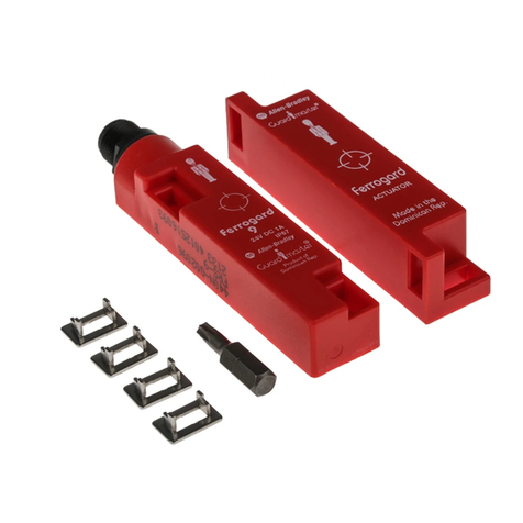
FERROGARD GD2
MAGNETICALLY ACTUATED INTERLOCK SWITCH
BERÜHRUNGSLOSER MAGNET-SCHALTER
INTERRUPTEUR DE SÉCURITÉ MAGNÉTIQUE INOX SANS CONTACT
(b) Description
The Ferrogard GD2 range of magnetically actuated, non-contact
safety interlock switches are used to stop machine power when a
guard is opened. When the stop signal is applied and the guard is
opened, the action of the actuator being removed from the switch
isolates the machine contactor control power. If redundancy and
monitoring is required, the Guardmaster Minotaur range of
monitoringunits should beconsidered.
Note:All Ferrogards haveinternal non-resettable overloadprotection.
Theyshould be protectedby an externalfuse ratedas shown at
step6.
Beschreibung
Die magnetisch betätigten, berührungslosen Magnet-Schalter der
Typenreihe Ferroguard GD2 werden zur Trennung der
Stromversorgung an eine Maschine bei Öffnung einer Schutztür
verwendet. Wenn das Stopsignal ausgelöst, und die Schutztür
geöffnetwird, wird der Betätiger durchdie Türbewegungvom Schalter
entfernt, und dadurch die Steuerstromzufuhr zum Schaltschütz der
Maschine getrennt. Für evtl. gewünschte Redundanz- und
Überwachungsfunktionen sollten die Überwachungsschalter der
Typenreihe Guardmaster Minotaurin Betracht gezogenwerden.
Anmerkung: Alle Ferroguard-Schaltelemente haben einen internen,
nicht-rückstellbaren Überlastungsschutz, und sollten deshalb durch
eine externe Sicherung mit den unter Schritt 6 angegebenen
Nennwertengeschützt werden.
Description
Le « Ferrogard GD2 » est un capteur magnétique de sécurité sans
contact pour porte de machine en acier inoxydable. Il coupe
l’alimentation électrique dès que celle-ci est ouverte. Quand la porte
est ouverte, le bloc contact du Ferrogard, séparé de son aimant, ouvre
le circuit du contacteur de puissance. Si un circuit redondant et auto-
contrôlé est nécessaire, il suffit de connecter les appareils de la
gamme Ferroguard avec ceux de la famille des blocs logiques
Minotaur( voir Guardmasterpour le choixdes appareils).
NOTE : Chaque Ferroguard est équipé d’une protection contre les
surcharges. Cette protection assure la sécurité de l’opérateur par
destruction d’un composant non remplaçable. Il doit donc être protégé
parun fusible externedont le calibreest définiau paragraphe 6.
Operation:targetfaceto target face
Einbauposition:Kontaktflächengegenüberliegend
Utilisation:face cible contre face cible
GuardStops
Recommendedgapbetweensensorandactuator.
EmpfohlenerAbstandzwischenSensorundBetätiger.
Ecartpréconiséentrelerécepteuretl’émetteur.
NOTE: ACTUATORMUSTNOTSTRIKESENSOR
ANMERKUNG: DERBETÄTIGERDARFDENSENSOR
NICHTBERÜHREN
REMARQUE: L’ÉMETTEURNEDOITPASHEURTERLE RÉCEPTEUR
2mm
(a)
1(b)
(d)
(e)
(c)
(a) NachMöglichkeit nur aufnicht-
ferritischenMaterialien montieren, um
eineBeeinflussung der
Funktionsabständezu vermeiden /
Sipossible, installer le Ferrogard sur
dessupportsnon magnétiques, afin de
nepas diminuer les distances dedétection
(c) Schutztürarretierungen/
Butéesdu panneau de protection
2
(b) Türgeschlossen /
Porte fermée
(c) SCHIEBETÜR/
Porte coulissante
(d) KeinZugang zum Schalter,dadurch
keineUmgehungsmöglichkeit der
Sicherheitsverriegelung/
Pasde possibilité d'accéder à l’appareil
pourle frauder
(e) Türgeöffnet, kein Zugangzum Schalter
/
Porte ouverte couvrantl’interrupteur
(c)
3
(a) SCHWENKBARE SCHUTZTÜREN
Schaltermontagean der Öffnungsseite
derSchutztür /
PORTESOU PROTECTEURS À CHARNIÈRES
Monterl’interrupteur surle bord ouvrant
dela porte de protection
(b) Fallswährend der Risikobewertung
entsprechendfestgestellt, muß eine
möglicheUmgehung des Schalters
durchZugangsverwehrungbei
geöffneterSchutztür verhindert werden
/
Sicela est imposé lors del'appréciation
durisque, limiter la neutralisation
del’interrupteur lorsde l’ouverture
duprotecteur
4 5
6(a) GD2 external fuse rating
(safety contacts) /
Sicherungs-Nennwerte für GD2
(Schutzkontakte) /
Curant nominal du fusible GD2
(contacts de sécurité)
7(a) CONNECTION / ELEKTRISCHE ANSCHLÜSSE / CONNEXION
Deutsch /
Français
(b) Ifrequiredbyariskassessment,reducethepossibilityoftheswitchbeing
defeatedbypreventingaccesstotheswitchwhentheguarddoorisopen.
(c) Ensurethattheswitchcannotbeactuatedunlesstheguardisinitsintendedposition.
(a)
LIFTOFF GUARDS
2mm ≥50mm
(c) Actuator Actuator
Switch
(b) Switch
Important / Wichtig / Important
(b) FerrogardGD2type Fusetype
1AC ≤1.6Aquickblow
1DC ≤800mAquickblow
2AC ≤1.6Aquickblow
2DC ≤800mAquickblow
20AC ≤1.6Aquickblow
20DC ≤800mAquickblow
21AC ≤1.6Aquickblow
21DC ≤800mAquickblow
(n) QuickBlow
(o) Fuseeachsafety
circuitexternally(see6)
AUXILIARY(types2,21)
EARTH(types1,2,20,21)
GREEN
YELLOW
YELLOW/GREEN
IMPORTANT
WICHTIG
IMPORTANT
8Afterinstallation check allofthe interlocked doorsto ensure that
themachine is isolatedandstopped whenever theguard is not closed.
Nacherfolgter Montage anallenabgesicherten Türen prüfen,ob die
Stromversorgungzur Maschine getrennt,unddie Maschine abgeschaltetwird, wenn
dieSchutztür nicht geschlossenist.
Aprèsinstallation, manoeuvrez chaqueportepour vous assurerde
l'arrêtde la machinetantque chaque protecteurn'est pas fermé.
BONDALLUNUSEDWIRESTOEARTH/ALLEUNBELEGTENKABELERDEN/
METTRETOUSLESFILSINUTILISÉSALATERRE
BLACK
SAFETY1(types1,2,20,21)
SAFETY2(types20,21)
WHITE
RED BLUE
4
(a) ABNEHMBARE SCHUTZABDECKUNGEN
/
PORTESOU PROTECTEURS AMOVIBLES
(b) FallswährendderRisikobewertung
entsprechendfestgestellt,mußeine
möglicheUmgehungdesSchalters
durchZugangsverwehrung bei
entfernterSchutzabdeckungverhindert
werden/
Sicela est imposé lors de
l'appréciationdu risque, limiter la
neutralisationde l’interrupteur lorsde
l’ouverture du protecteur
(c) Sicherstellen,daßderSchalternur
dannbetätigtwerdenkann,wenndie
Abdeckungangebrachtist/
S'assurer
queles conatcts ne peuvent pas être
activéstant que le protecteur n'est pas
danssa position définitive
5
(b) Schalter/
Interrupteur
(c) Betätiger/
Emetteur
(a)
6
(b) FerrogardTypGD2 Sicherungstp
1AC ≤1,6AFlinksicherung
1DC ≤800mAFlinksicherung
2AC ≤1,6AFlinksicherung
2DC ≤800mAFlinksicherung
20AC ≤1,6AFlinksicherung
20DC ≤800mAFlinksicherung
21AC ≤1,6AFlinksicherung
21DC ≤800mAFlinksicherung
/
TypeFerrogardGD2 Typedefusible
1c.alternatif
≤
Fusibleinstantané=1,6A
1c.continu
≤
Fusibleinstantané=800mA
2c.alternatif
≤
Fusibleinstantané=1,6A
2c.continu
≤
Fusibleinstantané=800mA
20c.alternatif
≤
Fusibleinstantané=1,6A
20c.continu
≤
Fusibleinstantané=800mA
21c.alternatif
≤
Fusibleinstantané=1,6A
21c.continu
≤
Fusibleinstantané=800mA
(b)
(c)
(i) (j)
(h)
(g)
(f)
(e)
(d)
(k)
(m)
(l)
7
(c) SCHUTZSCHALTUNG1
(Sicherungstyp1,2,20,21)/
Sécurité(types 1, 2, 20, 21)
(d) ROT/
ROUGE
(e) BLAU/
BLEU
(f) SCHWARZ/
NOIR
(g) WEISS/
BLANC
(h) GRÜN/
VERT
(i) GELB/GRÜN/
JAUNE/VERT
(j) GELB/
JAUNE
(k) ERDE(Sicherungstypen1,2,20,21)/
Terre (types 1, 2, 20,21)
(m) HILFSKONTAKTE (Typen2, 21) /
AUXILIAIRES(TYPES 2, 21)
(n) Flinksicherung/
Déclenchement
instantané
(o) JedenSchutzschaltkreisexternsichern
(siehe6)/
Munirchaque circuit de
sécuritéd’un fusible extérieur (voir 6)
(a)
Conformingtostandards EN1088, EN292,EN60204-1
Safetycontactarrangement
Types1AC,2AC ,for ACcircuitsonly 1N/Cspecialsafetyreed- 250VAC2A max
(fuseexternally1.6A quickblow)
Types20AC,21AC, forAC circuitsonly 2N/Cspecialsafetyreed-250VAC 2Amax
(fuseexternally1.6A quickblow)
Types1DC,2DC, forDC circuitsonly
1N/Cspecialsafety reed- 24VDC1ampmax
(fuseexternally800mA quickblow)
Types20DC,21DC, forDC circuitsonly
2N/Cspecialsafety reed- 24VDC1ampmax
(fuseexternally800mA quickblow)
Safetycontactoperating distance Make12mm -Break23mm
Auxiliarycontactoperating distance
Types
2& 21 Break10mm -Make13mm
Reedcontacts Safety Auxiliary
Closingtime 3.0mS 0.5mS
Dropouttime 2.1mS 0.3mS
Bouncetime 0.7mS 0.7mS
Shock 50G 100G
Vibration 7-15G’s,10to 200Hz
Initialcontactresistance 15mΩ1OmΩ
Initialcapacitance,terminals 0.65 pF 0.2pF
Initialinsulationres. terminals 1x 10⁶OHMS 1x10⁶OHMS
Min.initialb/down voltage 600VACRMS 600VACRMS
Auxiliarycontactarrangement
Types
2,21 1N/O
300VDC,250VAC(RMS) 0.5AINC.
INRUSH.15VA/10W.for AC/DCcircuits
Casematerial StainlessSteel BS3146Pt 2Anc4BFC
Protection IP68
Operatingtemperature –25°Cto 125°C
Fixing M4tamperresistant
Mountingconfiguration Anyposition
Mechanicallife 10x 106
Electricallife 1x 10⁶
Colour Silver
Cleaning Maybehigh pressuresteam cleaned
Cable Stranded7core. Flexiblethermoplastic
elastomersheathed7/0.5mm
NOTE:Thesafety contactsof theGuardmasterswitchesaredescribedas
normallyclosed(N/C) i.e.with theguardclosed,actuatorinplaceand the
machineableto bestarted.
(d) Technical Specifications
16
11.50
8
719.5 7
774.4
39.2539.25
78.5
16.75 16.75
16.75 16.75
33.5
62.5
11.5
5
62.5
19.5
33.5
78.50
4.4
8
6
(a) SWITCH
16
5
(b) ACTUATOR
9
39.2539.25
8
7
NormativeAuslegungentsprechend: EN 1088,EN 292,EN60204-1
Schutzkontaktanordnung
Typen1AC,2AC-nurfür AC-Schaltkreise 1 Spezial-Reed-Schutzkontakt-
250VAC, 2A max(Ruhekontakt).
(MitexternerFlinksicherung1,6Asichern)
Typen20 AC,21AC-nurfür 2Spezial-Reed-Schutzkontakte-
AC-Schaltkreise 250VAC, 2A max(Ruhekontakte).
(MitexternerFlinksicherung1,6Asichern)
Typen1DC,2DC-nurfürDC-Schaltkreise 1 Spezial-Reed-Schutzkontakt-
24VDC, 1A max(Ruhekontakt).
(MitexternerFlinksicherung800mAsichern)
Typen20 DC,21DC-nurfür 2Spezial-Reed-Schutzkontakte-
DC-Schaltkreise 24VDC, 1A max(Ruhekontakt).
(MitexternerFlinksicherung800mAsichern).
Schutzkontakt-Funktionsdistanz EIN=12 mm,AUS =23mm
Hilfskontakt-Funktionsdistanz
Typen2 und21 AUS=10mm,EIN=13mm
Reed-Kontakte Schutzkontakt Hilfskontakt
Schließzeit 3,0ms 0,5ms
Abfallverzögerung 2,1ms 0,3ms
Prellzeit 0,7ms 0,7ms
Stoß 50G 100G
Vibration 7-15 G,10 -200Hz
Anfängl.Kontaktwiderstand 15mΩ10 mΩ
Anfängl.Kapazität,Klemmen 0,65 pF 0,2pF
Anfängl.Isolierwiderstand,Klemmen 1 x 10 Ω1x10 Ω
Min.anfängl.Durchschlagsspannung 600V ACeff. 600VACeff.
Hilfskontakt-Auslegung
Typen2, 21 1Schließkontakt
300VDC, 250V AC(eff.),0,5AINKL.
EINSCHALTSTROM,15VA/10Wfür
AC/DC-Schaltkreise
Gehäusematerial RostfreierStahlBS3146Teil2Anc4BFC
Schutzklasse IP68
Betriebstemperatur -25°Cbis125°C
Montage M4,eingriffsicher
Montageanordnung InbeliebigerPosition
MechanischeLebendauer 10x 10
ElektrischeLebensdauer 1x 10
Farbgebung Silber
Reinigung KannmitHochdruckdampf erfolgen
Kabel Verseilt,7-adrig.Abschirmung
Thermoplastik-Elastomer7/0,5mm
ANMERKUNG: DieSchutzkontakteder Guardmaster-Schalterwerdenals
Ruhekontaktebeschrieben,d.h. beigeschlossener Schutztür,Betätigerin
Position,undstartbereiter Maschine.
Technische Daten Conformeauxnormessuivantes EN1088,EN292,EN 60204-1
Dispositiondescontacts desécurité
Types 1c. alternatif,2 c.alternatif 1 commutateuràlamesspécialN/F-
pourcircuitsc. alternatifseulement 250 V c. alternatif 2A maximal
(fusibleexterne :1,6A instantané)
Types20c.alternatif,21c.alternatif 2commutateurs àlamesspécial N/F -
pourcircuitsc. alternatifseulement 250 V c. alternatif 2A maximal
(fusibleexterne:1,6Ainstantané)
Types 1 c. continu, 2 c. continu 1 commutateur à lames spécial N/F -
pourcircuitsc.continuseulement Voyant24 V c. continu 2A maximal
(fusibleexterne:800mAinstantané)
Types 20 c. continu, 21 c. continu 2 commutateurs à lames spécial N/F -
pourcircuitsc.continuseulement Voyant24 V c. continu 2A maximal
(fusibleexterne:800mAinstantané)
Distancedeservice du contact de Contact : 12 mm
sécurité Coupure:23mm
Distancedeserviceducontactauxiliaire
Types 2 et 21 Contact: 10mm Coupure:13mm
Contactsdeslames Sécurité Auxiliaire
Tempsde fermeture 3,0ms 0,5ms
Tempsde désexcitation 2,1 ms 0,3ms
Tempsde saut 0,7ms 0,7ms
Décharge 50G 100G
Vibration 7- 15 G, 10 - 200 Hz
Résistancede contact initiale 15 mΩ10 mΩ
Capacitéinitiale, bornes 0,65 pF 0,2pF
Isolationinitiale, bornes rés. 1x10 Ω1x10 Ω
Tensionminimum initiale de 600V c. alternatif efficace
coupure
Dispositiondes contacts auxiliaires
types2,21 1N/O
300Vc.continu,250Vc.alternatif
(efficace)0,5Ainc.d’entrée,
15VA/10W pour circuits DC
Matériauduboîtier InoxBS3146Pt1Anc4BFC
Protection IP68
Température de service -25°C à 125°C
Fixation M4infraudable
Configurationdemontage Toutes positions
Duréedeviemécanique 10x10
Duréedevieélectrique 1x10
Couleur Argent
Nettoyage Peutêtrenettoyéàlavapeurhaute
pression
Câble Toronné 7 conducteurs, gaine
élastomèrethermoplastiquesouple
7/0,5mm
REMARQUE: lescontactsde sécurité desinterrupteursGuardmaster sont
décritscomme étantnormalementfermés (N/F) ;autrementdit, avec porte
deprotection fermée,émetteuren place etmachineen mesure dedémarrer.
Spécifications Techniques
9
(a) SCHALTER/
Récepteur
(b) BETÄTIGER/
Emetteur
6
6
66 66
6
6
Securityscrewdriver Pt.No:09018
Replacementsecuritykey Pt.No:09015
Replacementactuators are available by arrangement.
Note:Access to spare actuators should be restricted to
authorisedpersonnel to prevent bypassing of the safety function
Sicherheits-Schraubendreher Bestell-Nr. 09018
Sicherheits-Ersatzschlüssel Bestell-Nr. 09015
Austauschbetätigersind nach Vereinbarunglieferbar.
Anmerkung: DerZugang zu Austauschbetätigernsollte auf autorisierte
Personenbeschränkt werden, um Umgehungen der Schutzfunktion zu
verhindern.
Tournevis de sécurité- Nº de réf. : 09018
Cléde sécurité de rechange - Nº deréf. : 09015
Aimantsde rechange disponibles.
Note: l’accès aux aimants de rechange doit être strictement réduit
aupersonnel autorisé pour éviter la fraude de la fonction desécurité
.
ZUBEHÖR
(e) ACCESSORIES ACCESSOIRES
WARTUNG
(f) MAINTENANCE ENTRETIEN
EveryWeek
Inspect the switch casing & actuator for damage or distortion. Check
for correct alignment, see step 1. Replace or adjust where necessary.
Alsocheck operation of the switching circuit.
Chaquesemaine :
Inspecterle boîtier et l’aimant pour détecterles dommages et
vérifier les alignements (voir étape 1). Remplacer ou ajuster si
nécessaire. Tester lebon fonctionnement du circuit.
Wöchentlich
Schaltergehäuse und Betätiger auf Beschädigung oder Verziehung
überprüfen. Korrekte Ausrichtung prüfen, siehe Schritt 1. Falls
erforderlich, austauschen oderneu justieren. Ebenso die Funktion des
Schaltkreisesüberprüfen.
REPARATUR
(g) REPAIR RÉPARATIONS
In the event of a problem contact Guardmaster Ltd. If there is any
malfunction or damage, no attempts should be made to repair it. The
switch should be replaced before machine operation is allowed. If
appropriatereturn the switch to Guardmaster.
DONOT DISMANTLE THE UNIT.
Remplacez le fusible externe. Dans l’éventualité d’un problème
technique ou d’une détérioration de cet appareil Guardmaster, il doit
être remplacé immédiatement avant la remise en production de la
machine. Si cela est nécessaire, utilisez un formulaire de bon de
retouravant de le renvoyer chez Guardmaster.
DANSTOUS LES CAS, NE DISLOQUEZ PAS L'APPAREIL.
Bei eventuell auftretenden Problemen bitte mit Guardmaster
Ltd.Kontakt aufnehmen. Falls Fehlfunktionen oder Schäden
auftreten, keine Versuche zur Reparatur unternehmen. Der Schalter
muß vor erneuter Inbetriebnahme der Maschine ausgetauscht
werden. DenSchalter ggf. an Guardmaster zurücksenden.
DASGERÄT NIEMALS ZERLEGEN!
(h) TROUBLESHOOTING
Symptom
Safetycircuit fails to close
Auxiliarycircuit fails to open
Safetycircuit fails to open
Cause
Actuatormisaligned
Externalfuse blown
Internalfuse blown (incorrect installation)
Actuatormisaligned
Externalwiring fault
Remedy
Adjustalignment
Determinecause of overcurrent & remedy
Replaceswitch - fit external fuse.
Installas steps 1 & 2
Determine cause of fault & remedy. If the
faultisforeseeable,considerthe useof dual
channel techniques with a Guardmaster
Minotaurmonitoringsafety relay.
PARTOF THE E.J.A. ENGINEERINGGROUP
Guardmaster Ltd.
HindleyGreenInd.Est.Wigan,EnglandWN24HR
Tel:01942255166(Int:+441942255166)
Fax:01942523259(Int:+441942523259)
Guardmaster Sicherheitstechnik GMBH.
AmStadion15,42897Remscheid,Germany
Telefon:(02191)96850 Telefax:(02191)968520
Jusqu'au 31 décembre 1998 :
Guardmaster Sarl
274RueJulesFerry,95360Montmagny,France
Téléphone:0139836060-Télécopie:0139832800
A PARTIR DU 1er JANVIER 1999 :
Guardmaster Sarl
EUROCAP/COURTIMMO,BâtimentH1
62231COQUELLES,France
Téléphone:0321007374
Télécopie:0321001234
Siteinternet:http://www.guardmaster.fr
e-mail:[email protected]
DrgNo:20794 / IssueNo:0
ISO9001:1994
CertificateNo. FM 21701
This is to declare that the Guardmaster Ferrogard GD2 conforms with the Essential Health & Safety Requirements (EHSR's) of the European Machinery Directive
98/37/EC and the relevant requirements of the Low Voltage Directive (73/23/EEC as amended by 93/68 EEC). The Guardmaster Ferrogard GD2 also
conformstoEN 1088, EN 292, EN 60204-1.
SignedforGuardmaster Ltd
S.F.Mitchell
ManagingDirector
Declaration of Conformity / Konformitätserklärung / Déclaration de conformité
Symptom
Öffnerkreisschließt nicht
Hilfskontaktkreisschließt nicht
Öffnerkreisöffnet nicht
Ursache
Betätigerverschoben
ExterneSicherung angesprochen
InterneSicherung angesprochen
(nichtkorrekt angeschlossen)
Betätigerverschoben
Fehlerin der externen Verdrahtung
Beseitigung
InLinie montieren
Ursachefeststellen und beseitigen
Schalter ersetzen - Externe Sicherung
montieren
NachSchritt1 und2 montieren
Fehler voraussehbar ist, den Einsatz von 2-
kanaligen Techniken mit einem Relais-
Sicherheitsbaustein von GUARDMASTER
erwägen.
FEHLERSUCHE
Symptôme
Lecircuit de sécurité ne se ferme pas
Lecircuit auxiliaire ne s’ouvre pas
Lecircuit de sécurité ne s’ouvre pas
Cause
L’émetteurn’est pas aligné
Lefusible externe a sauté
Lefusible interne a sauté (mauvaise installation)
Emetteurnon aligné
Défautde câblage interne
Solution
Ajusterl’alignement
Déterminer la cause de la surintensité et
rectifier
Remplacer l’interrupteur - Monter un
fusibleexterne
Installerconformémentaux points 1 et 2
Déterminer lacause et rectifier. Sice
défautétait imprévisible, envisager
l’utilisationde techniques à deux canaux
avecun relais de sécurité de contrôle
GuardmasterMinotaur.
DÉPISTAGE DES DÉFAUTS

Other Guard master Switch manuals

Guard master PROSAFE RKSE Series User manual

Guard master

Guard master PROSAFE RKSE Series User manual

Guard master Elf GD2 User manual

Guard master

Guard master Elf GD2 User manual

Guard master TROJAN 5 User manual

Guard master

Guard master TROJAN 5 User manual

Guard master Centurion User manual

Guard master

Guard master Centurion User manual

Guard master TLS-3 GD2 User manual

Guard master

Guard master TLS-3 GD2 User manual

Guard master PROSAFE RPSE Series User manual

Guard master

Guard master PROSAFE RPSE Series User manual

Guard master Spartan Service manual

Guard master

Guard master Spartan Service manual

Guard master ATLAS 5-GD2 User manual

Guard master

Guard master ATLAS 5-GD2 User manual

Guard master Ferrogard Series User manual

Guard master

Guard master Ferrogard Series User manual

Popular Switch manuals by other brands

Vutlan VT335 quick start guide

Vutlan

Vutlan VT335 quick start guide

Key Digital KD-UFS42 quick start guide

Key Digital

Key Digital KD-UFS42 quick start guide

Alcatel-Lucent 7210 installation guide

Alcatel-Lucent

Alcatel-Lucent 7210 installation guide

Ross Synergy 1 SD manual

Ross

Ross Synergy 1 SD manual

NuTone SMART HOME NWD500Z quick start guide

NuTone

NuTone SMART HOME NWD500Z quick start guide

ZyXEL Communications Dimension ES-4024 Specifications

ZyXEL Communications

ZyXEL Communications Dimension ES-4024 Specifications

Cisco Small Business 200 Series quick start guide

Cisco

Cisco Small Business 200 Series quick start guide

Weidmüller Value Line IE-SW-VL05M Series Hardware installation guide

Weidmüller

Weidmüller Value Line IE-SW-VL05M Series Hardware installation guide

Vents SP3-1 quick start guide

Vents

Vents SP3-1 quick start guide

ZyXEL Communications GS1920 Series user guide

ZyXEL Communications

ZyXEL Communications GS1920 Series user guide

Philips 2net Gen 2 user manual

Philips

Philips 2net Gen 2 user manual

Tycon Power Systems TP-SW8GAT/24-SFP user manual

Tycon Power Systems

Tycon Power Systems TP-SW8GAT/24-SFP user manual

Cisco Nexus 7000 Series Configuration guide

Cisco

Cisco Nexus 7000 Series Configuration guide

Humminbird 531870-1_A Installation

Humminbird

Humminbird 531870-1_A Installation

PNI PT802P quick start guide

PNI

PNI PT802P quick start guide

Generac Power Systems CTTS Series specification

Generac Power Systems

Generac Power Systems CTTS Series specification

Aukey CB-H18 user manual

Aukey

Aukey CB-H18 user manual

HP SN6000B Quick start instructions

HP

HP SN6000B Quick start instructions

manuals.online logo
manuals.online logoBrands
  • About & Mission
  • Contact us
  • Privacy Policy
  • Terms and Conditions

Copyright 2025 Manuals.Online. All Rights Reserved.