manuals.online logo
Brands
  1. Home
  2. •
  3. Brands
  4. •
  5. Guard master
  6. •
  7. Switch
  8. •
  9. Guard master Ferrogard Series User manual

Guard master Ferrogard Series User manual

2.1 2.2
2.3
1
(p) No access to switch
thus preventing attempts
to defeat the interlock
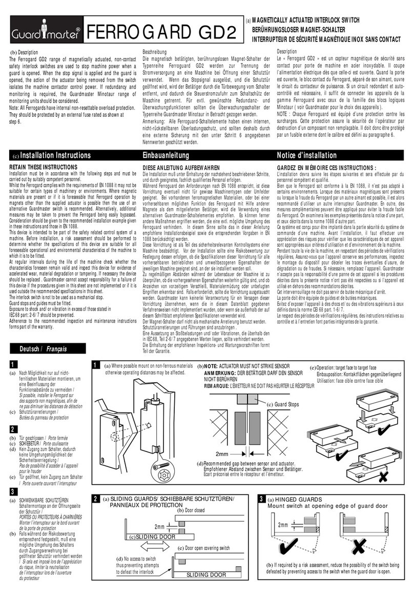
(e) Where possible mount on non-ferrous materials otherwise operating distances may be affected.
(j) NOTE: Using anaerobic thread locking compounds can have a detrimental
effect if they come into contact with the plastic switch case.
(h) Fixed guard
(g) Guard door
(i) M4
Resistorx
fixings
(f) Align targets
3
MAGNETICALLY OPERATED SAFETY SWITCH
MAGNET-SICHERHEITSSCHALTER
INTERRUPTEUR DE SECURITE MAGNETIQUES
SANS CONTACT
(c) RETAIN THESE INSTRUCTIONS
Installation must be in accordance with the following steps
and must be carried out by suitably competent personnel
DIESE ANLEITUNG AUFBEWAHREN
Die Montage ist entsprechend den folgenden Schritten durchzuführen
GARDEZ EN MEMOIRE CES INSTRUCTIONS
L'installation devra suivre les étapes suivantes et sera
effectuée par du personnel compétent et qualifié.
Einbauanleitung
(b) Installation Instructions Notice D'installation
Deutsch / Français
(e) Falls möglich, nicht auf
ferromagnetischem Material montieren,
Schaltabstand könnte reduziert werden
Si possible, installer le Ferrogard sur des
supports non magnétiques afin de ne pas
diminuer les distances de détection.
(f) Zielscheiben ausrichten /
Cible d’alignement
(g) Schutztür /
Porte
(h) Fester Maschinenteil /
Panneau fixe de machine
(i) M4-TORX-Schrauben /
Vis de sécurité M4
(j) Anmerkung: Die Benutzung von anaeroben
Klebern zur Fixierung kann Schäden am
Kunststoffgehäuse des Sensors verursachen
Note : L’utilisation de vernis de blocage peut
endommager le boîtier plastique en cas de contact.
(k) Schiebetüren /
Portes ou protecteurs coulissants
(m) Tür geschlossen, Maschine läuft
Porte fermée, machine en fonctionnement
(n) Tür offen (deckt Sensor ab), Maschine STOP
Porte ouverte, machine arrêtée
(p) Kein Zugang zum Sensor, somit werden
Umgehungsversuche verhindert
Pas de possibilité d’accéder à l’appareil
pour le frauder
(q) Schwenktüren /
Portes ou protecteurs à charnières
(r) Sicherstellen, daß Sensor bei offener
Schutztür nicht umgangen werden kann.
Anordnung nach 2.1 wählen.
S’assurer qu’il est impossible d’accéder à
l’appareil pour le frauder quand la porte est
ouverte. Se référer au principe présenté en 2.1
(s) Abnehmbare Schutzhauben
Portes ou protecteurs amovibles
(t) Sicherstellen, daß Sensor bei offener
Schutztür nicht umgangen werden kann.
Anordnung nach 2.1 wählen.
S’assurer qu’il est impossible d’accéder à
l’appareil pour le frauder quand la porte est
ouverte. Se référer au principe présenté en 2.1
(u) Sicherstellen, daß Sensor nur betätigt
werden kann, wenn Schutztür sich in
vorgesehener Stellung befindet.
S’assurer que les contacts ne peuvent pas
être activés tant que le protecteur n’est pas
dans sa position définitive.
(v) Schalter /
Appareil
(w) Betätiger /
Broche de maintien
See enclosed Declaration of Conformity for details.
Siehe Anlage: Konformitätserklärung.
Voir la declaration de conformite ci-jointe pour details.
(a) Description
The Ferrogard range of magnetically actuated,
non-contact safety interlock switches are used
to stop machine power when a guard is
opened. When the stop signal is applied and
the guard is opened, the action of the
actuator being removed from the switch
isolates the machine contactor control power.
If redundancy and monitoring is required, the
Guardmaster Minotaur range of monitoring
units should be considered.
Note: All Ferrogards have assured operation
and have internal non-resettable overload
protection. They should be protected by an
external fuse rated as shown in the
specifications table.
(a) Beschreibung
Die Reihe Ferrogard Magnetsicherheitsschalter
wird zum Abschalten des Maschinenantriebs
beim Öffnen einer Schutztür eingesetzt. Wenn
ein Stop-Signal anliegt und die Schutztür
geöffnet wird, wird durch das Entfernen des
Betätigers vom Sensor das Motorantriebsschütz
deaktiviert. Falls Redundanz und
Selbstüberwachung gefordert sind, sollte der
Einsatz der Relais-Sicherheitsbausteine
Minotaur erwogen werden.
Anmerkung: Alle Ferrogards sind intern mit
nicht-auswechselbaren Überlastsicherungen
versehen. Diese sind mit einer externen
Sicherung abzusichern (siehe Technische Daten).
(a) Description
Le « Ferrogard » est un capteur magnétique de
sécurité sans contact pour porte de machine. Il
coupe l’alimentation dès que celle-ci est ouverte.
Il est décliné suivant une large gamme. Quand la
porte est ouverte, le bloc contact du Ferrogard,
séparer de son aimant, ouvre le circuit du
contacteur de puissance. Si un circuit redondant et
auto-contrôle est nécessaire, il suffit de connecter
les appareils de la gamme Ferroguard avec ceux
de la famille des blocs logiques Minotaur (voir
Guardmaster pour le choix des appareils).
NOTE: Chaque Ferroguard est équipé d’une
protection contre les surcharges. Cette protection
assure la sécurité par destruction d’un composant
non remplaçable. Il doit donc être protégé par un
fusible externe dont le calibre est défini dans la
table en annexe.
SPECIALISTS IN MACHINERY SAFETY
Ferrogard
FRS 1, 2, 3, 4, 5, 6, 9, 10, 20DC, 21AC, 21DC, GS1 & GS2
(d) Whilst the Ferrogard complies with the requirements of EN 1088 it
may not be suitable for certain types of machinery or environments.
Where magnetic materials are present or if it is foreseeable that
Ferrogard operation by magnets other than the supplied actuator is
possible then the use of an alternative Guardmaster switch is
recommended. Other non- contact options include: Ferrotek or Ferrocode
which utilise additional coding techniques preventing them from being
overridden by simple means. Alternatively, additional measures may be
taken to prevent the Ferrogard being easily bypassed. Consideration
should be given to the recommended installation example given in the
instructions and those in EN 1088.
Bien que le Ferrogard soit conforme à la EN 1088, il n'est pas adapté à
certains environnements. Lorsque des matériaux magnétiques sont
présents ou lorsque la fraude du Ferrogard par un autre aimant est
possible, il est alors recommandé d'utiliser un autre interrupteur
Guardmaster. Les autres options sans contact sont le Ferrotek et le
Ferrocode qui utilisent, en plus, des techniques de codage, les protégeant
de la fraude par un simple aimant. D'autre part, il est possible de mettre
en place des mesures supplémentaires pour éviter que le Ferrogard ne
soit facilement fraudé. Pour cela, il faut prendre en considération
l'exemple d'installation donné dans les instructions de montage, ainsi
que dans la EN 1088.
Der Ferrogard erfüllt zwar die Anforderungen von EN 1088, kann aber
moglicherweise dennoch für bestimmte Typen von Maschinen oder
Umgebungen nicht zulässig sein. Wenn magnetische Materialien vorhanden
sind oder es voraussehbar ist, daß der Ferrogard durch andere als den
mitgelieferten Betätiger geschaltet werden kann, wird die Verwendung
eines anderen Guardmaster-Schalters empfohlen. Diese können sein:
Ferrotek oder Ferrocode, welche zusätzliche Codiertechniken einsetzen, so
daß sie mit einfachen Mitteln nicht umgangen werden können. Alternativ
können auch Zusatzmaßnahmen ergriffen werden, um das Umgehen des
Ferrogard zu verhindern. Das in unserer Montageanleitung empfohlene
Beispiel sowie die Ausführungen in der EN 1088 sollten beachtet werden.
✘
✘
✔
✔✔
✔
2mm
(m) Door closed, machine RUN
(n) Door open covering switch, machine STOP
(r) Ensure that the switch can not be defeated when
the guard is open. Refer to principle shown in 2.1.
(t) Ensure that the switch can not be defeated when
the guard is open. Refer to principle shown in 2.1.
(u) Ensure that the switch can not be actuated unless the guard is in its intended position.
SLIDING DOOR
(k)
SLIDING GUARDS
(q)
HINGED GUARDS
(s)
LIFT OFF GUARDS
SLIDING DOOR
2mm
✔
✔✘
✘
2mm ≥50mm
(w) Actuator Actuator
Switch(v) Switch
Important / Wichtig
查询2044供应商 捷多邦,专业PCB打样工厂,24小时加急出货
5.2
4(x) Ferrogard external fuse rating
(safety contacts)
5.1 Ferrogard 1, 2, 20, 21, GS1 & GS2
5.3
5.4 (s1) OPTIONAL PLUG-IN CONNECTOR
(x) Nennwerte der externen
Sicherung (Öffnerkontakt)
Table des fusibles externes Ferrogard
(y) Ferrogard Typ /
Type Ferrogard
(z) Externe Sicherung (flink)
Fusible externe ultra-rapide
(a1) Braun /
Marron
(b1) Blau /
Bleu
(c1) Öffner (Sicherung extern)
Sécurité (fusible externe)
(d1) 1 Öffner /
1N/C (contact de sécurité)
(e1) Schwarz /
noir
(f1) Weiß /
Blanc
(g1) 1 Schließer /
1N/O contacts auxiliaires
(h1) Rot /
Rouge
(i1) Schließer /
auxiliaire
(j1) Grün /
Vert
(k1) Gelb /
jaune
(m1) Öffner (nur 21) (Sicherung extern)
Sécurité (21 seulement) (fusible externe)
(n1) 1 Öffner (Hilfsk.)
1N/C contacts auxiliaires = 3+4
(p1) Sicherung (flink) /
Fusible ultra rapide
(q1) Jeden Sicherheitskreis extern
absichern (siehe Schritt 4)
Chaque contact de sécurité doit être équipé
d’un fusible de protection externe (voir étape 4)
(r1) Anschlüsse /
Connexions
(s1) Wahlweise mit Steckverbinder
Connecteur à fiche supplementaire
(t1) Rot+Blau /
Rouge+Bleu
(u1) Rot /
Rouge
(v1) Rot+Schwarz /
Rouge+Noir
(w1) Rot+Weiß /
Rouge+Blanc
(x1) Rot+Gelb /
Rouge+Jaune
(y1) Grün /
Vert
(y) Ferrogard type (z)External quick
blow fuse
FRS 1 ≤1.6A
FRS 2 ≤1.6A
FRS 3 ≤1.6A
FRS 4 ≤1.6A
FRS 5 ≤1.6A
FRS 6 ≤1.6A
FRS 9 ≤800mA
FRS 10 ≤2.5A
FRS 20DC ≤800mA
FRS 21AC ≤1.6A
FRS 21DC ≤800mA
GS1 ≤1.6A
GS2 ≤1.6A
Ferrogard 3, 4 & 5 Ferrogard 6, 9 & 10
Ferrogard 1 (FRS 1) GS1 & GS2
(d1) 1 N/C (Safety Contacts)
Ferrogard 20 (FRS 20)
(d1) 2 N/C (Safety Contacts)
Ferrogard 2 (FRS 2)
(d1) 1 N/C (Safety Contacts)
(g1) 1 N/O (Aux Contacts)
Ferrogard 21 (FRS 21)
(d1) 2 N/C (Safety Contacts)
(g1) 1 N/O (Aux Contacts) (p1) Quick Blow
(q1) Fuse each safety
circuit externally
(see Step 4)
(a1) Brown
(b1) Blue
(b1) Blue (c1) Safety (fuse externally)
(i1) Auxiliary
(m1) Safety (21 only) (fuse externally)
(e1) Black
(f1) White
(j1) Green
(k1) Yellow
(h1) Red
IMPORTANT
/ WICHTIG
(p1) Quick Blow
(q1) Fuse each safety
circuit externally
(see Step 4)
IMPORTANT
/ WICHTIG
(b1) Blue (c1) Safety
(fuse externally)
(a1) Brown
(c1) Safety
(fuse externally) (c1) Safety
(fuse externally)
(e1) Black
(f1) White
Ferrogard 2 (FRS 2)
(d1) 1 N/C (Safety Contacts)
(g1) 1 N/O (Aux Contacts)
(p1) Quick Blow
(q1) Fuse each safety
circuit externally
(see Step 4)
(b1) Blue (c1) Safety
(fuse externally)
(i1) Auxiliary
(e1) Black
(f1) White
(a1) Brown
IMPORTANT
/ WICHTIG
Ferrogard 20 (FRS 20)
(d1) 2 N/C (Safety Contacts)
(b1) Blue (c1) Safety
(fuse externally)
(c1) Safety
(fuse externally)
(e1) Black
(f1) White
(a1) Brown
Ferrogard 21 (FRS 21)
(d1) 2 N/C (Safety Contacts)
(g1) 1 N/O (Aux Contacts)
(u1) Red (c1) Safety
(fuse externally)
(c1) Safety
(fuse externally)
(v1) Red+Black
(w1) Red+White
(t1) Red+Blue
(i1) Auxiliary
(x1) Red+Yellow
(y1) Green
(r1) Connection Details
Ferrogard 3 (FRS 3)
(d1) 1 N/C Safety Contacts = 1& 2
(n1) 1 N/C Aux. Contacts = 3& 4
Ferrogard 4 (FRS 4)
(d1) 1 N/C Safety Contacts = 1& 2
(g1) 1 N/O Aux. Contacts = 3 & 4
Ferrogard 5 (FRS 5)
(d1) 1 N/C Safety Contacts = 1& 2
1234
(p1) Quick Blow
(q1) Fuse each safety
circuit externally
(see Step 4)
IMPORTANT
/ WICHTIG
(d1) 1 N/C Safety Contacts
(b1) Blue (a1) Brown
Ferrogard 6 & 9 (FRS 6 & FRS 9)
(d1) 1 N/C Safety Contacts
(b1) Blue (a1) Brown
6After installation check all of the interlocked doors to ensure that
the machine is isolated and stopped whenever the guard is not closed.
Nach der Montage an allen Schutztüren prüfen, ob die Maschine
beim Öffnen der Schutztür abgeschaltet wird.
Après installation, manoeuvrez chaque porte pour vous assurer de
l'arrêt de la machine tant que chaque protecteur n'est pas fermé.
Deutsch / Français
Technical Specifications
Conforming to standards EN1088, EN292, EN60204-1
Contact arrangement (safety)
(FRS 1, 2, 3, 4, 5, 6, GS1 & GS2) 1N/C special safety reed
(FRS 21AC) 2N/C special safety reed
For AC circuits only 250VAC 2A max.
(fuse externally 1.6A quick blow)
(FRS 9) 1N/C special safety reed
(FRS 20DC & 21DC) 2N/C special safety reed
For DC circuits only 24VDC 1A max.
(fuse externally 800mA quick blow)
(FRS 10) 1N/C special safety reed
For AC circuits only 110VAC 3A max.
(fuse externally 2.5A quick blow)
Contact arrangement (auxiliary)
(FRS 2, 4 & 21) 1N/O
(FRS 3) 1N/C
300VDC, 250VAC (RMS) 0.5A INC.
INRUSH. 15VA/10W. for AC/DC circuits
Case material (Ferrogards) Moulded ABS
(GS1 & GS2) Stainless steel or Brass
Protection (FRS1,2,6,9,10,20DC&21) IP67
(FRS 3, 4 & 5) IP65
(GS1 & GS2) IP68
Operating temperature (Ferrogards) -10°C to +65°C
(GS1) -10°C to +80°C
(GS2) -10°C to +125°C
Fixing (Ferrogards) M4 tamper resistant
(GS1 & GS2) M3 tamper resistant
Mounting Any position
Safety contact operating distance Make 12mm - Break 23mm
Auxiliary contact operating distance
(FRS 2, 4 & 21) Break 10mm - Make 13mm
(FRS 3) Break 24mm - Make 21mm
Mechanical life 10 x 106
Electrical life 1 x 10⁶
Cable (FRS 21) 6 core flexible
(FRS 1, 6, 9 & 10) 24/0.2 (0.75mm2) 2 core flexible
(FRS 2) 16/0.2 (0.5mm2) 4 core flexible
(FRS 20DC) 4 core flexible
(GS1) PVC 2 core flexible
(GS2) Polyolefin 2 core
Reed contacts Safety Auxiliary
Closing time 3.0mS 0.5mS
Drop out time 2.1mS 0.3mS
Bounce time 0.7mS 0.7mS
Shock 50G 100G
Vibration 7-15G’s, 10 to 200Hz
Initial contact resistance 15mΩ1OmΩ
Initial capacitance, terminals 0.65 pF 0.2pF
Initial insulation res. terminals 1 x 10⁶OHMS 1 x 10⁶OHMS
Min. initial B/down voltage 600VAC RMS 600VAC RMS
Colour (Ferrogards) Red
(GS1 & GS2) Stainless steel or brass
Cleaning (excluding FRS 3, 4 & 5) May be high pressure steam cleaned
GS2 certification Baseefa Cert. No. Ex 81122, ExsIIT6
Technische Daten
Entspricht den Normen EN1088, EN292, EN60204-1
Öffnerkontakte:
(FRS 1, 2, 3, 4, 5, 6, GS1 u. GS2) 1Ö Spezielles Sicherheits-Reedrohr
(FRS 21AC) 2Ö Spezielles Sicherheits-Reedrohr
Nur für AC 250VAC 2A max.
(externe Sicherung 1,6 A fl.)
(FRS 9) 1Ö Spezielles Sicherheits-Reedrohr
(FRS 20DC & 21DC) 2Ö Spezielles Sicherheits-Reedrohr
Nur für DC 24VDC 1A max.
(externe Sicherung 800 mA flink)
(FRS 10) 1Ö Spezielles Sicherheits-Reedrohr
Nur für AC 110VAC 3A max.
(externe Sicherung 2,5 A flink)
Schließerkontakte: (FRS 2, 4 u. 21) 1S
(FRS 3) 1Ö
300 VDC, 250 VAC eff., 0,5 A einschl.
Einschaltstrom, 15 VA/10 W.
Geeignet für AC u. DC
Gehäuse (Ferrogards) ABS, Farbe rot
(GS1 u. GS2) Ms oder Niro
Schutzart (FRS1,2,6,9,10,20DC&21) IP67
(FRS 3, 4 & 5) IP65
(GS1 u. GS2) IP68
Betriebstemperatur (Ferrogards) -10 bis +65°C
(GS1) -10 bis +80°C
(GS2) -10 bis +125°C
Befestigung (Ferrogards) Sicherheitsschrauben (TORX) M4
(GS1 u. GS2) Sicherheitsschrauben (TORX) M3
Montagelage Beliebig
Schaltabstand Öffner (alle) AN 12 mm - AUS 23 mm
Schaltabstand Hilfskont.
(FRS 2, 4 & 21) AUS 10 mm - AN 13 mm
(FRS 3) AN 21 mm - AUS 24 mm
Mechanische Lebensdauer 10 x 106 Schaltspiele
Elektrische Lebensdauer 1 x 10⁶ Schaltspiele
Anschlußleitung (FRS 21) 6-adrig, 2m
(FRS 1, 6, 9 & 10) 2 x 0,75 mm2, 2m
(FRS 2) 4 x 0,5 mm2, 2m
(FRS 20DC) 4-adrig, 2 m
(GS1) 2-adrig PVC, 2m
(GS2) 2-adrig Polyolefin, 3m
Reedkontakte Öffnerkont. Hilfskont.
Schaltzeit Schließen 3.0mS 0.5mS
Schaltzeit Öffnen 2.1mS 0.3mS
Prelldauer 0.7mS 0.7mS
Schockfestigkeit 50G 100G
Erschütterungen 7-15G’s, 10 to 200Hz
Kontaktübergangswid. 15mΩ1OmΩ
Kapazität Anschlüsse 0.65 pF 0.2pF
Isolationswid. Anschl. 1 x 10⁶OHMS 1 x 10⁶OHMS
Überschlagspannung 600VAC RMS 600VAC RMS
Farbe (Alle) Rot
(GS1 & GS2) Niro oder Ms
Ex-Zulassung GS2 Baseefa Cert. No. Ex 81122, ExsIIT6
Specifications Techniques
Conforme aux normes EN1088, EN292, EN60204-1
Type de contacts (sécurité)
(FRS 1, 2, 3, 4, 5, 6, GS1 & GS2) 1N/C reed de sécurité spéciale
(FRS 21AC) 2N/C reed de sécurité spéciale
Pour circuit VAC seulement 250 VAC 2A max
(fusible externe 1.6A ultra-rapide)
(FRS 9) 1N/C reed de sécurité spéciale
(FRS 20DC & 21DC) 2N/C reed de sécurité spéciale
pour alimentation VDC seulement 24VDC 1A max
(fusible externe 800mA ultra-rapide)
(FRS 10) 1N/C reed de sécurité spéciale
Pour circuit VAC seulement 110VAC 3A max
(fusible externe 2.5A ultra-rapide)
Type de contacts (auxiliaire)
(FRS 2, 4 & 21) 1N/O
(FRS 3) 1N/C
300VDC, 250VAC (RMS) 0.5A INC.
INRUSH. 15VA/10W. Pour circuits AC/DC
Boîtier (Ferrogards) Moulé ABS
(GS1 & GS2) Acier inoxydable ou laiton
Protection (FRS1,2,6,9,10,20DC&21) IP67
(FRS 3, 4 & 5) IP65
(GS1 & GS2) IP68
Température de (Ferrogards) -10°C to +65°C
fonctionnement (GS1) -10°C to +80°C
(GS2) -10°C to +125°C
Fixations (Ferrogards) M4 vis non fraudatoire
(GS1 & GS2) M3 vis non fraudatoire
Montage Toute position
Distance d’enclenchement des Enclenchement 12mm -
contacts de sécurité Déclenchement 23mm
Distance d’enclenchement des contacts
auxiliaires:(FRS 2, 4 & 21) Déclenchement10mm-Enclenchement13mm
(FRS 3) Déclenchement24mm-Enclenchement 21mm
Vie mécanique 10 x 106
Vie électrique 1 x 10⁶
Cable (FRS 21) 6 conducteurs flexibles
(FRS 1, 6, 9 & 10) 24/0.2 (0.75mm2) 2 conducteurs flexibles
(FRS 2) 16/0.2 (0.5mm2) 4 conducteurs flexibles
(FRS 20DC) 4 conducteurs flexibles
(GS1) PVC 2 conducteurs flexibles
(GS2) Polyolefin 2 Conducteurs
Contact REED Sécurité Auxiliaire
Temps de fermeture 3.0mS 0.5mS
Temps d’ouverture 2.1mS 0.3mS
Temps de rebond 0.7mS 0.7mS
Résistance au choc 50G 100G
Vibration 7-15G’s, 10 to 200Hz
Résistance de contact initiale 15mΩ1OmΩ
Capacité initiale, bornes 0.65 pF 0.2pF
Isolation aux bornes 1 x 10⁶OHMS 1 x 10⁶OHMS
Tension de rupture min. 600VAC RMS 600VAC RMS
Couleur (Ferrogards) Rouge
(GS1 & GS2) Acier inoxydable ou laiton
Nettoyage (àl'exclusiondeFRS3, 4 &5) Peut être nettoyéau jet vapeurhaute pression
Certification GS2 Baseefa Cert. No. Ex 81122, ExsIIT6
15
5
FERROGARD 6,9 & 10
(v) SWITCH
84
16
6
54
7
4
11
4
19
12
46
46
(w) ACTUATOR
19
7
19
7
4.54.5 73
4.54.5 73
==
82
==
FERROGARD 3,4 & 5
25
36
69
(v) SWITCH
57
6
38
38.5
2 x M4 ==
50
6
(w) ACTUATOR
15
5
2
7
19.5
608
76
==
5
==
30
4
==
FERROGARD 1, 2, 20DC & 21
8
=19.5 =
4
==
76
==
30
60
5
2
5
==
608
=19.5
30
=
=76 =
4
15-19
(v) SWITCH
15
5
2
7
(w) ACTUATOR
54
46
11
12
22
6.5
114.5 19
16
19 13
54
67
6.5
33.5
GS1 & GS2 (t1) ACTUATOR
127
20
(v) SWITCH (w) SWITCH
60
30
17
25
7
FERROGARD GS2FERROGARD GS1
PART OF THE E.J.A. ENGINEERING GROUP
Security screwdriver Pt. No: 09018
Replacement security key Pt. No: 09015
Replacement actuators are available by arrangement.
Note: Access to spare actuators should be restricted to
authorised personnel to prevent bypassing of the safety function
TORX-Bit-Handhalter Bestell-Nr. 09018
TORX-Bit Bestell-Nr. 09015
Ersatzbetätiger sind nach Vereinbarung erhältlich.
Der Zugang zu diesen ist auf autorisierte Personen zu be-
schränken, um Mißbrauch zu verhindern.
Tournevis de sécurité Ref. No: 09018
Embout de sécurité Ref. No: 09015
Aimants de rechange disponibles.
Note: L’accès aux aimants de rechange doit être strictement réduit
au personnel autorisé pour éviter la fraude de la fonction de sécurité.
Guardmaster Ltd.
Hindley Green Ind. Est. Wigan, England WN2 4HR
Tel: 01942 255166 (Int: +441942 255166)
Fax: 01942 523259 (Int: +44 1942 523259)
Guardmaster Sicherheitstechnik GmbH.
Am Stadion 15, 42897 Remscheid, Deutschland
Telefon: (02191) 96850 Telefax: (02191) 968520
Guardmaster Sarl
274 Rue Jules Ferry, 95360 Montmagny, France
Téléphone: 01 39 83 60 60
Télécopie: 01 39 83 28 00
Drg No: 20688 / Issue No:1 / change note no: 12005
ZUBEHÖR
(z1) ACCESSORIES ACCESSOIRES
WARTUNG
(a2) MAINTENANCE MAINTENANCE
Every Week
Inspect the switch casing & actuator for damage or distortion. Check
for correct alignment, see step 1. Replace or adjust where necessary.
Also check operation of the switching circuit, see step 6.
Every 6 months
Isolate all power! Remove the switch lid where relevant (FRS 3, 4
& 5) with the security bit provided. Inspect all terminals for
tightness. Clean out any accumulation of fine dirt etc. Replace
covers & fully tighten the security screws. Reinstate the power &
check for correct operation.
Chaque semaine
Inspecter le boîtier et l’aimant pour détecter les dommages et vérifier
les alignements (voir étape 1). Remplacer ou ajuster si nécessaire.
Tester le bon fonctionnement du circuit, voir étape 6.
Tous les 6 mois
Couper l’alimentation. Retirer le couvercle de l’appareil (pour les
modèles FRS3, 4 & 5) avec l’outil fourni. Inspecter la propreté des
bornes et le serrage. Nettoyer toute accumulation de fines saletés,
etc. Replacer le couvercle. Serrer les vis. Remettre l’alimentation et
contrôler le bon fonctionnement du circuit.
Wöchentlich
Schaltergehäuse und Betätiger auf Beschädigungen prüfen. Korrekte
Ausrichtung prüfen, siehe Schritt 1. Falls notwendig, ersetzen oder neu
einstellen. Ebenso Funktion des Schaltkreises überprüfen, siehe Schritt 6.
Wenigstens alle 6 Monate
Spannung abschalten! Deckel (FRS 3, 4, 5) mit dem mitgelieferten
TORX-Bit abnehmen. Alle Anschlüsse auf festen Sitz überprüfen.
Jeglichen feinen Staub und Schmutz entfernen. Deckel wieder
aufsetzen und sorgfältig befestigen. Spannung einschalten und auf
korrekte Funktion überprüfen.
REPARATUR
(b2) REPAIR REPARATION
In the event of a problem contact Guardmaster Ltd. If there is any
malfunction or damage, no attempts should be made to repair it. The
switch should be replaced before machine operation is allowed. If
appropriate return the switch to Guardmaster.
DO NOT DISMANTLE THE UNIT.
Remplacez le fusible externe. Dans l’éventualité d’un problème
technique ou d’une détérioration de cet appareil Guardmaster, il doit
être remplacé immédiatement avant la remise en production de la
machine. Si cela est nécessaire, utilisez un formulaire de bon de
retour avant de le renvoyer chez Guardmaster.
DANS TOUS LES CAS, NE DISLOQUEZ PAS L'APPAREIL.
Bei auftretenden Problemen bitte mit Guardmaster Kontakt aufnehmen.
Falls Fehlfunktionen oder Schäden auftreten, keine Versuche zur Reparatur
unternehmen. Der Schalter muß ersetzt werden, bevor die Maschine
wieder gestartet wird. Ggf. Schalter an Guardmaster zurückschicken.
GERÄT NIEMALS AUSEINANDERNEHMEN.
FEHLERSUCHE
(c2) TROUBLESHOOTING LOCALISATION DE PANNE
Symptom
Safety circuit fails to close
Auxiliary circuit fails to open
Safety circuit fails to open
Cause
Actuator misaligned
External fuse blown
Internal fuse blown (incorrect installation)
Actuator misaligned
External wiring fault
Remedy
Install as steps 1 & 2
Determine cause of overcurrent & remedy
Replace switch & install as step 4
Install as steps 1 & 2
Determine cause of fault & remedy. If the
fault is foreseeable, consider the use of dual
channel techniques with a Guardmaster
Minotaur monitoring safety relay.
Symptom
Öffnerkreis schließt nicht
Hilfskontaktkreis schließt nicht
Öffnerkreis öffnet nicht
Ursache
Betätiger verschoben
Externe Sicherung angesprochen
Interne Sicherung angesprochen
(nicht korrekt angeschlossen)
Betätiger verschoben
Fehler in der externen Verdrahtum
Beseitigung
Nach Schritt 1 u. 2 montieren
Ursache feststellen und beseitigen
Schalter austauschen und nach Schritt 2
neu montieren
Nach Schritt 2 neu montieren
Ursache feststellen und beseitigen. Falls
Fehler voraussehbar ist, den Einsatz von 2-
kanaligen Techniken mit einem Relais-
Sicherheitsbaustein von GUARDMASTER
erwägen.
Symptôme
Le contact de sécurité ne se ferme pas
Le contact auxiliaire ne s’ouvre pas
Le circuit de sécurité ne s’ouvre pas
Cause
Aimant mal aligné
Fusible externe grillé
Fusible interne grillé (mauvaise installation)
Aimant mal aligné
Panne sur câblage machine
Solution
Suivre étape 1 & 2
Déterminer la cause de surtension et y remédier
Changer l’appareil et suivre étape 4
Suivre étape 1 & 2
Déterminer la cause de la panne et y
remédier. Si la panne persiste, utiliser un
relais de sécurité Minotaur à 2 canaux de
Guardmaster.

This manual suits for next models

13

Other Guard master Switch manuals

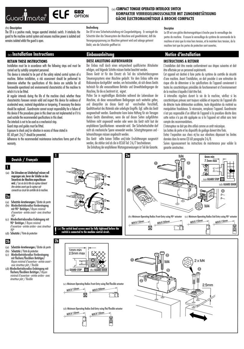
Guard master Elf GD2 User manual

Guard master

Guard master Elf GD2 User manual

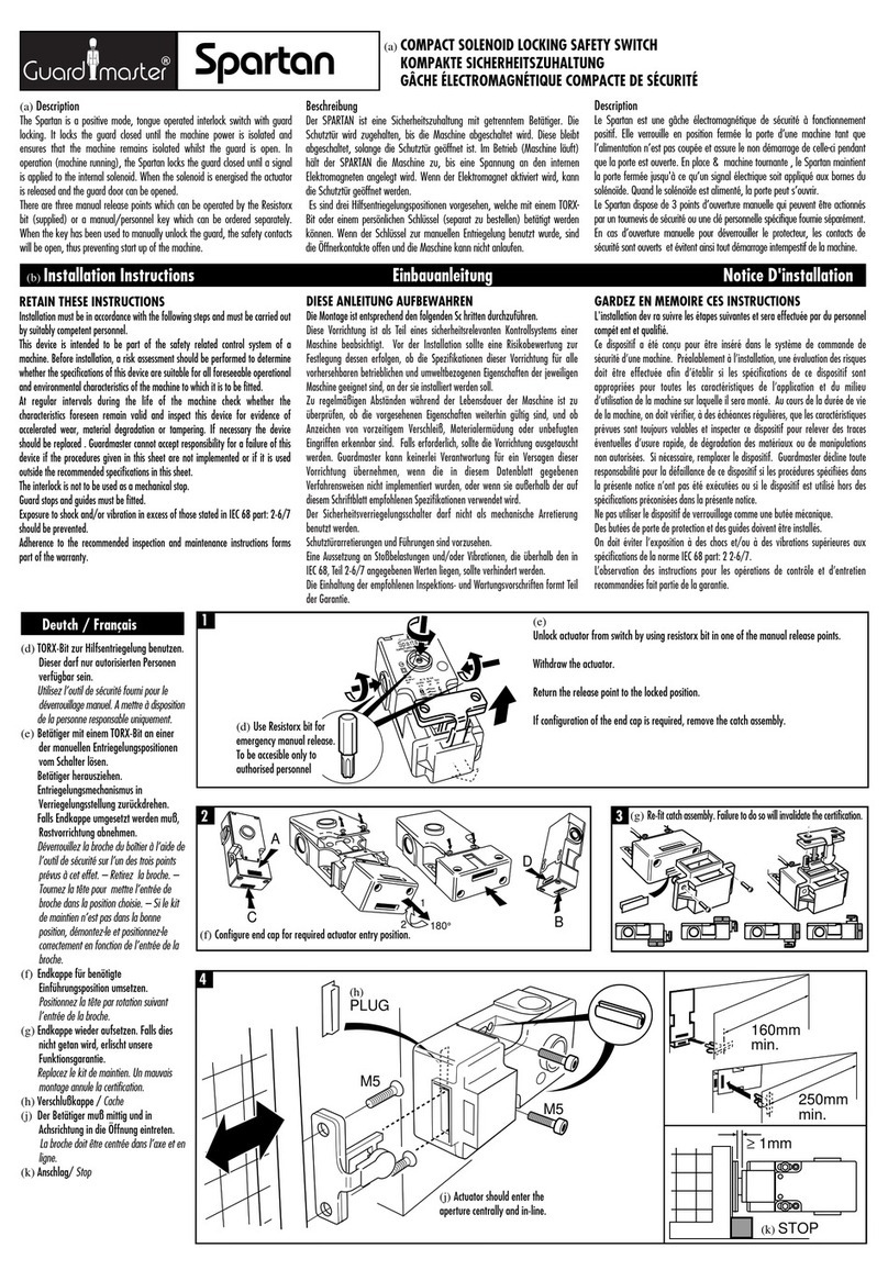
Guard master Spartan Service manual

Guard master

Guard master Spartan Service manual

Guard master PROSAFE RPSE Series User manual

Guard master

Guard master PROSAFE RPSE Series User manual

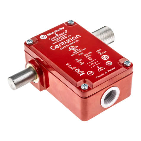
Guard master Centurion User manual

Guard master

Guard master Centurion User manual

Guard master PROSAFE RKSE Series User manual

Guard master

Guard master PROSAFE RKSE Series User manual

Guard master TROJAN 5 User manual

Guard master

Guard master TROJAN 5 User manual

Guard master ATLAS 5-GD2 User manual

Guard master

Guard master ATLAS 5-GD2 User manual

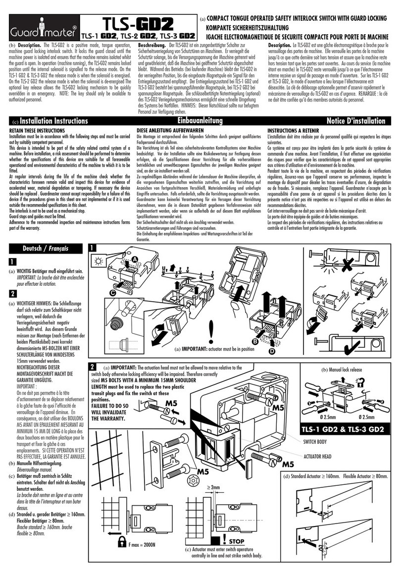
Guard master TLS-3 GD2 User manual

Guard master

Guard master TLS-3 GD2 User manual

Guard master FERROGARD GD2 User manual

Guard master

Guard master FERROGARD GD2 User manual

Popular Switch manuals by other brands

TRENDnet TE100 PCIWN Quick installation guide

TRENDnet

TRENDnet TE100 PCIWN Quick installation guide

Siemens QPL Series instruction manual

Siemens

Siemens QPL Series instruction manual

Pakedge SE-8 quick start guide

Pakedge

Pakedge SE-8 quick start guide

Edimax GS-1026 datasheet

Edimax

Edimax GS-1026 datasheet

Ruijie RG-CS83 Series Hardware  installation and reference guide

Ruijie

Ruijie RG-CS83 Series Hardware installation and reference guide

Brocade Communications Systems FCX624S-HPOE Step-by-step guide

Brocade Communications Systems

Brocade Communications Systems FCX624S-HPOE Step-by-step guide

Panasonic TB5560187 user manual

Panasonic

Panasonic TB5560187 user manual

IDT 89HPES24T6G2 user manual

IDT

IDT 89HPES24T6G2 user manual

Hanwell IKVM-101Plus user manual

Hanwell

Hanwell IKVM-101Plus user manual

ADTRAN 1534/1544 installation guide

ADTRAN

ADTRAN 1534/1544 installation guide

Belkin HI-SPEED USB 2.0 EXTERNAL DRIVE ENCLOSURE user manual

Belkin

Belkin HI-SPEED USB 2.0 EXTERNAL DRIVE ENCLOSURE user manual

SMART SE240 quick reference

SMART

SMART SE240 quick reference

ICPDAS iNS-300 Series user manual

ICPDAS

ICPDAS iNS-300 Series user manual

Microbit AS-1289 user manual

Microbit

Microbit AS-1289 user manual

CTC Union GSW-1005MS user manual

CTC Union

CTC Union GSW-1005MS user manual

Davey RainBank installation instructions

Davey

Davey RainBank installation instructions

Symbol WS 2000 Quick installation guide

Symbol

Symbol WS 2000 Quick installation guide

Avaya C360 Manager Installation and configuration

Avaya

Avaya C360 Manager Installation and configuration

manuals.online logo
manuals.online logoBrands
  • About & Mission
  • Contact us
  • Privacy Policy
  • Terms and Conditions

Copyright 2025 Manuals.Online. All Rights Reserved.