Gutermann AQUASCOPE 3 User manual

AQUASCOPE 3
Operating Manual
JW V 1.3 Date 12/10/2012

AQUASCOPE 3
Version 1.3 1/19
Contents
1. Introduction...........................................................................................................2
1.1. System Components....................................................................................2
2. How to Switch on the Amplifier.........................................................................3
3. Connecting the Headphones.............................................................................3
4. The Hand probe Microphone.............................................................................4
4.2 Techniques using the hand probe Microphone with Rods.....................4
4.3 How to find leaks with the AQUASCOPE 3 listening stick.....................5
4.4 Techniques using the hand probe Microphone with Tripod...................6
4.5 How to find Leaks with the AQUASCOPE 3 Tripod foot.........................7
5. The Ground Microphone/Geophone ................................................................8
5.2 Techniques using the Geophone................................................................8
6. How to find leaks with the AQUASCOPE 3 Geophone...............................10
7. Aquascope Pocket Microphone......................................................................11
8. Wearing the Control Unit..................................................................................13
9. Operation of the AQUASCOPE 3...................................................................14
9.1 The display and the button function.........................................................14
9.2 Keyboard functions.....................................................................................15
10. Battery replacement.......................................................................................17
11. Technical Specifications................................................................................17
12. Trouble Shooting............................................................................................18
13. Appendix..........................................................................................................19

AQUASCOPE 3
Version 1.3 2/19
1. Introduction
Welcome to the AQUASCOPE 3 leak detection system. The
AQUASCOPE 3 is a digital acoustic leak locator with superior crystal
clear sound with simple to use operation. It’s light weight with a waist
strap for user comfort. The on board digital leak noise analysis displays
the real leak noise level without effect from ambient sounds. To aid pin
pointing while sounding the leak noise is automatically memorised and
the last 8 reads are available for comparison.
The AQUSCOPE 3 has a filter system which allows the operator to
finely tune the narrow band-pass filter to suppress unwanted
interference and background noise while focusing on the leak noise.
The system has a versatile hand probe for direct sounding and leak
location on soft ground. For the ground microphone or combined
locator system a shielded robust ground microphone (Geophone) with
its high performance sensor is available for pin pointing through hard
surfaces.
1.1.System Components
Depending on which AQUASCOPE 3 system was purchased, the
following configuration is supplied:
All Configuration Types include
Amplifier control unit with waist belt
Stereo Headphones
Connection Cable
Hand probe Locator (see chapter 4)
Hand probe microphone
3 x Probe rods including 1 with a tip
1 x Tripod and magnet
Ground Mic Locator (see chapter 5)
Geophone
T bar handle and rod
Combined Locator
All of the above components.
Pmic Kit
Pocket microphone
3 Probe rods including 1 with tip
Ground plate and magnet (optional)

AQUASCOPE 3
Version 1.3 3/19
2. How to Switch on the Amplifier
The amplifier does not have an on/off switch, the cable performs that
task. Once the connecting cable is plugged into the amplifier (control
unit), the amplifier switches on and will remain on until the cable is
unplugged. When switched on, the display will show the battery charge,
filter setting, volume setting and the signal strength.
Note: In order to save battery consumption, please ensure that the
cable is disconnected from the amplifier after using the AQUASCOPE
3.
3. Connecting the Headphones
The headphone is connected to the AQUASCOPE 3 control unit via the
3.5mm stereo socket on the right side of the display. There is a volume
control on the headphone cable for adjustment for your comfort of
sound level. Coil any excess cable so to avoid rubbing against the
microphone which can create unwanted noise.
Fig. 3 Neatly Coiled Cable Fig. 4 Poorly Coiled Cable
Fig. 1 Plug in Cable Fig. 2 Display is On (Stand-by)

AQUASCOPE 3
Version 1.3 4/19
4. The Hand probe Microphone
Screw the desired amount of probe rods together as required, generally
an extension together with the Tip rod is recommended. Next, attach
the rod assembly to the hand probe microphone. The longer the rod
assembly the more background noise is introduced especially on windy
days. Some people lag the rod with pipe insulation to reduce wind
noise. The hand probe is used for direct sounding on pipes and fittings.
For direct sounding we recommend to use the “filter off” mode.
4.2Techniques using the hand probe Microphone with Rods
The following photos show example methods of using the
AQUASCOPE 3 hand probe:
Fig.5 Hand probe Component Parts
Fig.6 Hand prob e Assembly
usin g 2 x rod sections
Fig.7 Hand probe Assembl y
with Cabl e Attached
Fig.8 Listening directl y on a
Water Meter
Fig.9 listen ing directl y
on a Valve or Hydrant

AQUASCOPE 3
Version 1.3 5/19
Caution: when probing through the soil it’s highly
recommended that a certified insulated probe such as a punch bar is
used. This helps prevent the possibility of electrical shock or damaging
the aluminium rods while probing through the ground.
4.3How to find leaks with the AQUASCOPE 3 listening stick
An electronic listening stick is usually used to perform a leakage survey
by walking the street listening on every valve, hydrant and accessible
service connection. Each sounding is usually for 10 to 30 seconds. It
takes longer to assess the noise when there is more background
noise. It is not unusual to perform this work at night in busy cities when
the pressure is highest and the background noise is lowest. It is
important to hold the stick still and firmly pressed against the pipe,
valve or hydrant. Ensure there is no long grass or cables making
contact with the stick.
The electronic listening stick is usually a localization tool used to
localize the leak position; however when the leak is suspected to be in
a pipe under soft ground, the electronic listening stick can be used to
pinpoint the leak. It is preferable to make the hole with an electrically
insulated punch bar or another probe and then insert the stick into the
hole made. Extreme Care should be taken to ensure there is no
contact with other underground services. Check with your company
Health and Safety Officer before proceeding with this method.
1. Listen on all fittings in an area making note of the noise level,
frequency and characteristics. It is usual to listen at each location for a
period of 10 to 30 seconds, waiting for background noise to stop. If
Fig.10 listening directly on
a pipe with th e rod inserted
through soft soil
Fig.11 listening to the pipe
via an insulated toughened
probe

AQUASCOPE 3
Version 1.3 6/19
there is noise generated from consumption, pumps, road works or
heavy traffic you will need to return when the noise stops.
2. Note the minimum noise detected on each reading on a map.
3. Analyse the minimum noise levels on the map to identify the area of
interest.
4. Use a pipe locator to trace and mark the pipe location in the area of
interest and check to see if there are any other services in the same
trench as your pipe.
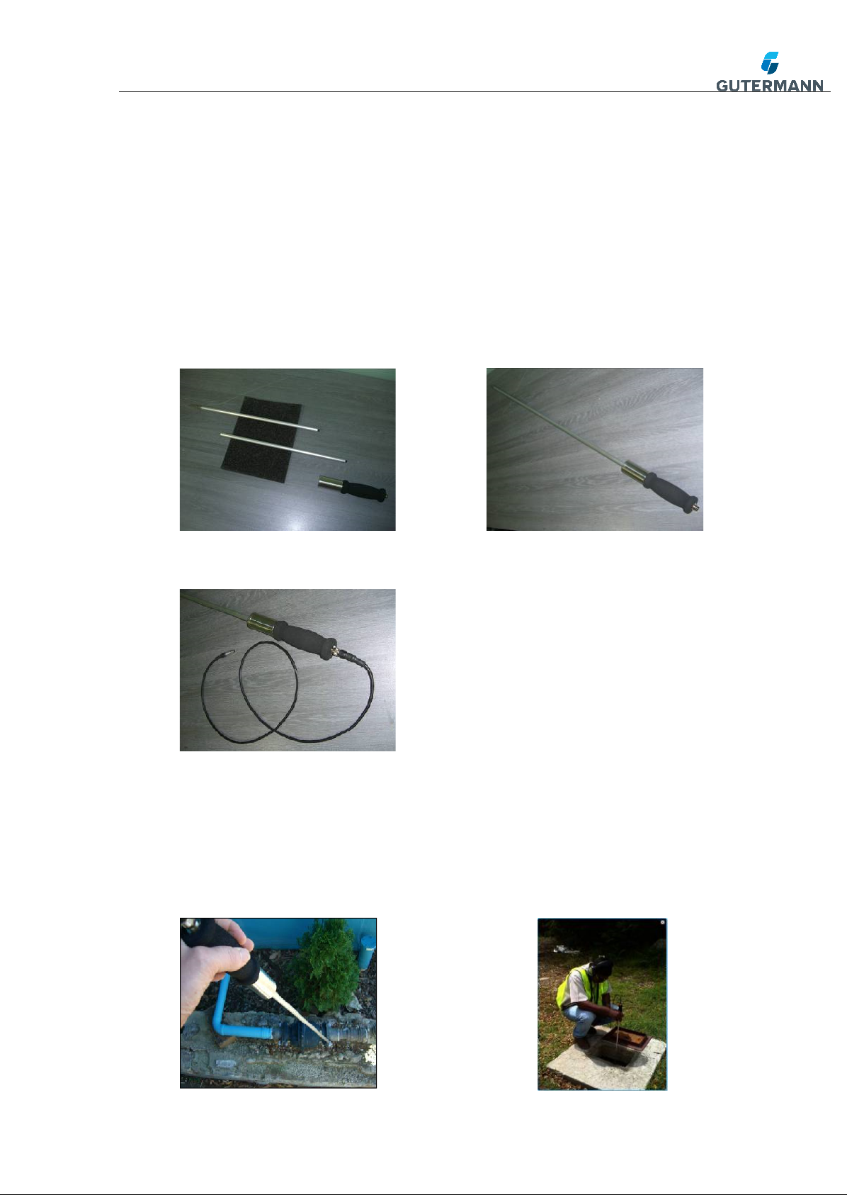
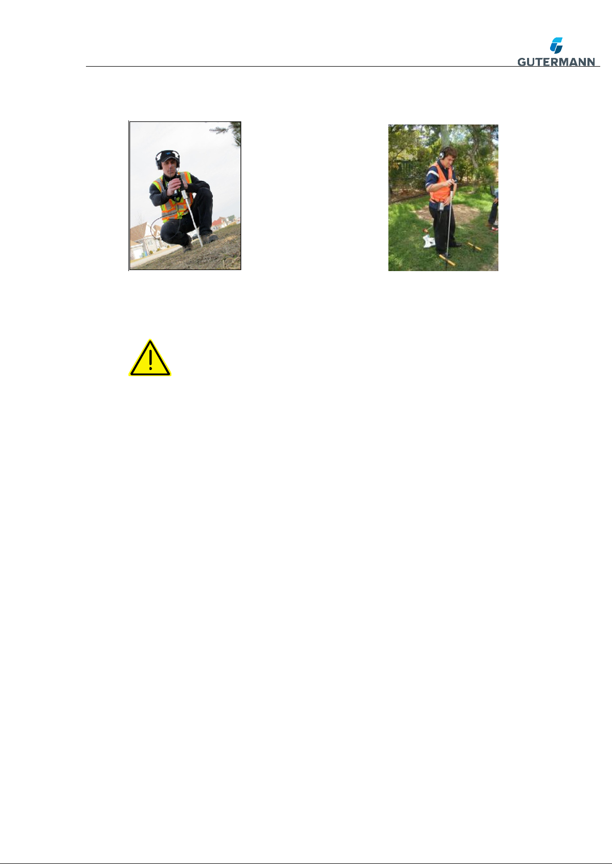
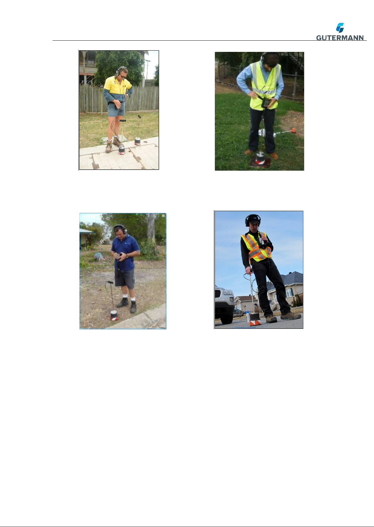
5. If it is safe to do so, make a series of holes at 3 meter intervals in the
ground with an insulated punch bar and insert the probe from the
electronic listening stick into the ground as deep as it is safe.
6. Continue this process along the section of pipe work until the leak is
found. Holes will need to be made at 1 meter intervals when the leak
has been located to a 6 meter span.
7. Determine which point has the loudest minimum noise.
8. Perform a “star check” moving about 30 cm from this point to all 8
points of a star. Each point should have a lower noise than the pin-
pointed leak position. If a point has a louder noise than the centre, this
could be the correct position, repeat the star check to verify.
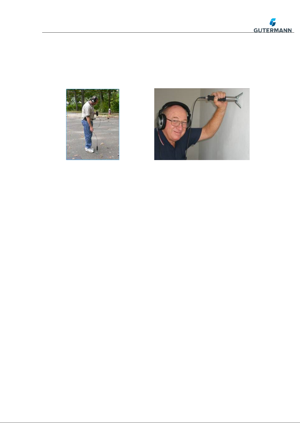
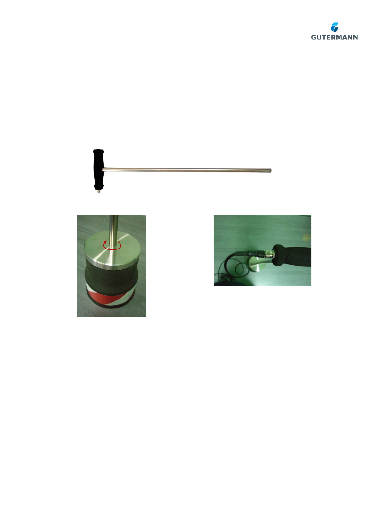
4.4Techniques using the hand probe Microphone with Tripod
The hand-probe tripod attachment is used to find leaks buried in
concrete slab, walls and shallow ground. This microphone has less
sensitivity than the ground microphone which makes it possible to pin
point leaks in such conditions. Too much amplification can be
confusing to the operator. Screw the magnet into the sensor and attach
to the tripod foot. Lift or move the hand-probe to each point and then
listen.
Fig.12 Tripod & magnet
Fig.13 magn et

AQUASCOPE 3
Version 1.3 7/19
The following photos show example methods of using the
AQUASCOPE 3 hand probe with Tripod:
4.5How to find Leaks with the AQUASCOPE 3 Tripod foot
The tripod foot is a pinpointing tool that attaches to the electronic
listening stick in place of the probe bars. It is used to find leaks in
concrete slab, shallow underground pipes and in walls. It should
always be placed or held in a still position during operation.
1. Localise the leak position with noise loggers or an electronic listening
stick. If a Correlator is available this can be used to narrow down the
location to a much smaller area.
2. It is best practice to locate the pipe position with a pipe locator.
3. Follow the path of the pipe listening for the leak at 1 meter
intervals. Each sample should last long enough to capture a minimum
noise value, typically 20 to 30 seconds.
4. When the location with the highest minimum noise has been identified
use your leakage experience to confirm this is a leak noise.
5. Perform a “star check” moving about 30 cm from this point to all 8
points of a star. Each point should have a lower noise than the pin-
pointed leak position. If a point is louder this could be the correct
position, repeat the star check to verify.
Fig.14 using th e tripod
attached to th e hand probe
micr ophone
Fig.15 listening to a leak ing
pipe through the wall

AQUASCOPE 3
Version 1.3 8/19
5. The Ground Microphone/Geophone
To assemble the Geophone, take the T-bar handle and screw into the
stainless steel plate of the Geophone base in a clockwise direction.
There should be no thread visible once complete. When attaching the
cable ensure the notch lines up between the 4 way plug on the cable
and the socket of the T-Bar.
Fig.16 T-Bar handle for Geophone
o
5.2Techniques using the Geophone
Use the Geophone to surface sound and pin point on compact earth,
concrete and tarmac. When sounding on grass use a hand-probe or a
piece of plywood to act as a sounding board, this will help to reduce the
tickling sound caused by the blades of grass on the Geophone sensor.
Fig.18 Screw the 4 way pl ug of the
connection cabl e into the han dle
Fig.17 Threading the T-bar handle
into the Ge ophone base

AQUASCOPE 3
Version 1.3 9/19
When using the Geophone to pin point the leak move along the path of
the pipe in regular (1ft or 300mm) intervals taking a reading at each
point, this is depicted by the diagram fig 23 (PTO) which shows a
buried pipe and the Geophone taking readings at regular intervals. Use
the memory button (see section 8.2) to analysis the results and return
to the loudest point to confirm the leak.
Fig.22 sounding using th e Geophone
on Tarmac
Fig.20 sounding using the
Geophone on grass with a
wooden board
Fig.21 sounding using the
Geophone on compact earth
Fig.19 sounding using the
Geophone con cret e

AQUASCOPE 3
Version 1.3 10/19
Fig.23 Method of Pin Pointing with a Geophone
In clay soils there maybe 2 high readings with a lower reading in
between due to the water leak created a cavity and the water hitting the
walls of the cavity.
6. How to find leaks with the AQUASCOPE 3
Geophone
The ground microphone is a pinpointing tool that is used to find leaks
under sealed surfaces. It has more sensitivity than the tripod foot
which is an advantage in finding leaks in deeper pipes but a
disadvantage finding leaks in good noise conductors like concrete slab.
It should always be placed or held in a still position during operation.
1. Localise the leak position with noise loggers or an electronic listening
stick. If a Correlator is available this can be used to narrow down the
location to a much smaller area.
2. It is best practice to locate the pipe position with a pipe locator.
3. Follow the path of the pipe listening for the leak at 1 meter
intervals. Each sample should last long enough to capture a minimum
noise value, typically 20 to 30 seconds.
4. When the location with the highest minimum noise has been identified
use your leakage experience to confirm this is a leak noise.
5. Perform a “star check” moving about 30 cm from this point to all 8
points of a star. Each point should have a lower noise than the pin-
pointed leak position. If a point is louder this could be the correct
position, repeat the star check to verify.

AQUASCOPE 3
Version 1.3 11/19
7. Aquascope Pocket Microphone
Fig.24 Pocket Mic
The Pocket Microphone (Pmic) is a versatile microphone that
comprises of a trigger handle attached to a rubberised microphone via
a flexible cable. The Pmic can take various attachments including the
ground plate, magnet or rods. The Pmic connects to the control unit by
pushing and screwing the binder plug into the Aquascope socket.
Fig.25 Pocket Mic Handle Trigger
There are 2 methods of activating the sound by either pushing the
trigger on the handle or the button on the Aquascope 3 control unit.
Fig.26 Pocket Mic Rods
Screw the rods directly onto the Pmic or onto the ground plate to create
a listening stick used to sound on valves, taps, hydrants, pipes and
meters. See Handprobe section 4.2 for further detail.

AQUASCOPE 3
Version 1.3 12/19
Fig.27 the Magnet Attachment
Screw the magnet to the ground plate or directly to the Pmic as shown
above. The magnet is perfect for listening directly on fittings where the
leak is quite and difficult to distinguish if you use a rod and are having
problems holding the microphone completely still.
Fig.28 Pocket Mic as a Ground Microphone
With or without the ground plate attached the pocket mic can be used
to pin point a leak under hard surfaces such as concrete and asphalt.
Move the Pmic along the path of the pipe step by step to find the
loudest point, use your leak values and memory recall as a reference.
See Aquascope 3 Geophone section 5.2 for further detail on technique.

AQUASCOPE 3
Version 1.3 13/19
8. Wearing the Control Unit
Fig.29 Waisted Mounted Control Unit
Attach the Aquascope3 control unit around the waist using the webbing
strap and quick release clips provided. The waist band can be adjusted
to suit. An alternative method of holding the control unit is around the
neck using the waist band.

AQUASCOPE 3
Version 1.3 14/19
9. Operation of the AQUASCOPE 3
9.1The display and the button function.
Fig.30 AQUASCOPE 3 Display
1. Filter setting - On the upper left-hand corner the filter setting is
shown. Either “Filter off” or “Filter on” plus the centre frequency of the
selected narrow-band band-pass filter (e.g. 700 Hz).
2. Battery charge - On the upper right-hand corner is a battery symbol
indicating the actual battery charge.
3. Volume - In the upper part of the display from left to right is a bar
showing the selected volume level.
4. Signal strength - In the lower part of the display, starting from the
left-hand side, the actual signal strength is indicated in the signal
strength bar.
5. Minimum noise level - On the lower right-hand corner, the minimum
noise level (value between 00 and 99) is indicated during a listening
session. From the moment the “listen” button is pressed (until
released), the AQUASCOPE-3 automatically samples and records the
lowest noise level, indicating the true leak noise without ambient
interference. When the “listen” button is released, this value will
automatically be saved in the memory. The last 8 leak values can be
recalled on your display.
On the upper side of the amplifier, on the left-hand side of the display,
is the “listen” button. When pressing this button the operator can listen

AQUASCOPE 3
Version 1.3 15/19
to the leak noise at each sounding point. Press and hold the button
until you are confident the background noise has gone. When releasing
the button, the amplifier will return to the mute mode. This will
automatically store the leak noise value in the memory.
9.2 Keyboard functions
Fig.31 AQUASCOPE 3 Keyboard
On the front label panel is 5 keys which allow selection and change of
the settings at any given moment.
1. Volume – the 2 blue buttons on the left hand side are for volume
control + to increase and – to decrease.
2. Filters – the 2 green buttons on the right hand side are to adjust the
filters + to increase the frequency and – to reduce the frequency.
3. Memory – the red M button is to activate the memory recall of the
latest 8 Noise Levels

AQUASCOPE 3
Version 1.3 16/19
4. Back light – to activate the display backlight press both blue buttons
together simultaneously.
Note: When the backlight is switched on, the battery consumption
will triple and thus reduce the battery life!!
In order to save battery consumption: If for a period exceeding
10 seconds none of the keys including the “listen” button is pressed,
the backlight will automatically be switched off. As soon as any of
the keys are pressed, the backlight will automatically switch on
again.
5. Activate Filters - to turn the filter on or off press the 2 green buttons
together simultaneously. When ambient noises and background
interference disturb the leak sounding survey, the operator can
switch to the “filter on” mode. This will activate a narrow band pass
filter. It can be adjusted by using the upper key to increase or the
lower key to reduce the centre frequency in order to suppress any
unwanted interference and background noise, and to adjust the
audible range to the exact leak noise frequency. The centre
frequency can be adjusted between 200Hz and 5000Hz. On the
display the selected setting is indicated by “filter on” plus the centre
value of the actual band pass currently being used.
Fig. 33 Activating the Filter
Fig.32 M button pressed an d the last 8 readings displayed

AQUASCOPE 3
Version 1.3 17/19
10. Battery replacement
At the back of the amplifier is the battery compartment. Please lift the
battery compartment cover. There are 4 LR6 (AA) size alkaline
batteries. When the battery charge indicator on the display suggests
replacing the batteries, please make sure that all 4 batteries are
replaced at the same time. When inserting the batteries please observe
the correct direction (+ and – according to the indicated position).
11. Technical Specifications
1.
The control unit should be manufactured from a high
strength PVC material that is resistant to exposure from
high levels of UV exposure.
2.
Power supply comprises of 4 x standard LR6” or “AA”
Alkaline batteries.
3.
The System has a Frequency range of 1 – 5000Hz
4.
The control unit has amplification of 60DB or more.
5.
The Sensitivity in the hand probe is 15v/g or more.
6.
The Sensitivity in the ground microphone is 20 v/g or more.
7.
The Aquascope 3 has a display showing battery status,
noise level, volume setting and signal strength.
8.
The center frequency of a band-pass filters shown as a
numeric value. The operator tunes into the exact filter
setting required in increments of 40Hz.
9.
Activating the filters only takes one simple button press.
10.
The filter settings have a narrow bandwidth to allow for
optimal acoustic tuning of the leak noise.
11.
The ground microphone to cable connector is at a height
greater than 400mm from the floor so it cannot be
accidentally kicked by the operator.
12.
The ground microphone to controller cable runs within the
ground microphone handle, this reduces exposure to
increased background noise from wind.

AQUASCOPE 3
Version 1.3 18/19
12. Trouble Shooting
Fault
Cause
Solution
No Sound
A Damaged cable or
Headphones.
Headphone Volume
control is too low
Replace connection
cable or headphones.
Increase headphone
volume control.
No Display
Dead batteries
Replace batteries
No Display
Cable fault
Replace connection
cable
Noise Level
25,no sound
Cable fault
Replace connection
cable
Corrupt
Display
Circuit Board
Return to Gutermann
Sound in 1
earpiece
Headphone
Replace Headphone
Cannot plug in
hand probe or
Geophone
Damaged connection
socket
Return to Gutermann

AQUASCOPE 3
Version 1.3 19/19
13. Appendix
The AQUASCOPE 3 connection cable has change overtime, the main
difference between each cable variant is the plug and socket on the
control unit. The various types of connector are shown below:
Fig. 29 Type 1; Oldest version Fig. 30 Type 2; 3way connector
Fig. 31 Type 3; Latest version (Binder) Fig. 32 Type 4; Australia only
Table of contents
Other Gutermann Measuring Instrument manuals
Popular Measuring Instrument manuals by other brands

Pfeiffer Vacuum
Pfeiffer Vacuum QMG 422 operating instructions

Burkert
Burkert 8228 ELEMENT neutrino operating instructions

Sonotec
Sonotec SONAPHONE RD operating manual

MEASUREMENT TECHNOLOGY
MEASUREMENT TECHNOLOGY LCI-90 installation manual

Fluke
Fluke i400s quick start guide

Novus
Novus NVR-6304P4A-H1-II quick start guide