GYS 40FV User manual

7
3502
-
V1
-
10/07
/2013
P
: 3
-
5
/ 1
8
-
20
P : 6-8 / 18-20
S : 9-11 / 18-20
P : 12-14/18-20
CT : 15-18/18-20

2
1
Afficheur Display
Anzeige
Pantalla
Дисплей
2
Boutons de r glages Adjustment buttons
Einstelltasten
Teclas de reglajes
Кнопки регулировки
3
Voyant jaune de
protection thermique
Thermal protection
indicator (yellow)
Übertemperatur-
anzeige, gelb
Indicador luminoso
amarillo de protección
t rmica
Желтый индикатор
температурной
защиты
4
Voyant d faut torche Torch fault light
Brennerstörung-LED
Piloto defecto
antorcha
Индикатор горелки
5
Voyant d faut d’air Air fault light
Druckluftstörung-LED
Piloto defecto de aire
Индикатор воздуха
6
Mode mesure de la
pression
Air Pressure
Measurement Mode
Druckmessungs-
Modus
Modo medida de la
presión
Режим измерения
давления
7
Mode tole grillag e Metal Mesh mode
Gitterschneide- Modus
Modo chapa tipo rejilla
Режим решётчатой
горелки
8
Bouton de
changement de mode Mode selection button
Taste zum Ändern des
Modus
Botón de cambio de
modo
Кнопка изменения
режима
9
Mode tôle pleine Sheet metal mode
Blechschneide-Modus
Modo chapa llena
Режим листового
металла
3
4
5
9
7
6
8
1
2
(A)
(mm)
█
–
zone recommand e
Recommended zone
Empfohlener Schneidbereich
Zona recomendada
рекомендуемая зона
█
–
zone de s paration
Separation zone
Möglicher Schneidbereich
Zone inestable
малостабильная зона

3
DESCRIPTION
Merci de votre choix ! Afin de tirer le maximum de satisfaction de votre poste, veuillez lire avec attention ce qui suit :
PLASMA CUTTER 40FV est un d coupeur plasma Inverter, portable, monophas . Il permet de d couper en courant
continu (DC) les aciers, les inox, aluminium, cuivre.
ALIMENTATION-MISE EN MARCHE
•
Cet appareil est livr avec une prise 16A de type CEE7/7 et dispose d’un système « Flexible Voltage ». Il s’alimente
sur une installation lectrique comprise entre 85V et 265V (50 - 60 Hz) AVEC terre et est prot g pour le
fonctionnement sur groupes lectrogènes. Le courant effectif absorb (I1eff) est indiqu sur l'appareil, pour les
conditions d'utilisation maximales. V rifier que l'alimentation et ses protections (fusible et/ou disjoncteur) sont
compatibles avec le courant n cessaire en utilisation.
•Cet appareil à usage professionnel, classe A, est destin à être connect à des r seaux priv s raccord s au r seau
public d’alimentation seulement en moyenne et haute tension. Il n’est pas pr vu pour être utilis dans un site
r sidentiel où le courant lectrique est fourni par le système public d’alimentation basse tension. Il peut y avoir des
difficult s potentielles pour assurer la compatibilit lectromagn tique dans ces sites, à cause de perturbations
conduites aussi bien que rayonn es.
Ce mat riel ne respecte pas la CEI 61000-3-12. Avant de les connecter au système public d’alimentation basse
tension, il est de la responsabilit de l’utilisateur de s’assurer qu’il peut y être reli . Consulter si n cessaire l’op rateur
de votre r seau de distribution lectrique.
•
Ne pas utiliser dans un environnement comportant des poussières m talliques conductrices.
MISE EN ROUTE ( oir interface page 2)
•Raccorder l’appareil au r seau lectrique et au r seau d’air comprim . Au pr alable fixez, sur le filtre r gulateur,
l’embout de raccordement pneumatique adapt à votre installation.
• Allumer l’appareil grâce au commutateur situ à l’arrière du poste.
• Relier la pince de masse sur une zone d cap e de la pièce à souder.
• R gler la pression.
• Choisir le mode tôle pleine ou tôle grillag e à l’aide du bouton mode (8).
• R gler le courant de d coupe à l’aide des boutons r glages (2).
• D couper.
MODE DE DÉCOUPE ( oir interface page 2)
Mode tôle pleine :
Choisir ce mode lorsque la tôle n’est pas ajour e.
La d coupe peut s’arrêter de 2 façons :
olors du relâch de la gâchette.
olorsque l’arc ne rencontre plus le m tal à d couper.
Mode tôle grillagée :
Choisir ce mode lorsque la tôle à d couper est ajour e. Ce mode permet de garder l’arc amorc même si
celui-ci d bouche sur un vide.
La d coupe s’arrête par relach de la gâchette ou au bout de 3 secondes sans rencontrer de m tal.
Pendant la phase de d coupe ou de refroidissement de la torche, si la pression d’air sort de la plage recommand e le
voyant (5) clignote. Il avertit l’utilisateur que la pression employ e n’est pas optimale.
REGLAGE DE LA PRESSION ( oir interface page 2)
Mode mesure d’air (manomètre intégré) :
Quand ce mode est s lectionn l’afficheur indique l’unit de pression utilis , bar ou PSI.
Un appui long sur le bouton mode (8) permet de choisir l’unit de mesure.
Pour commencer la mesure appuyer brièvement sur la gâchette, l’air sort de la torche et la pression est
affich e suivie d’une lettre. « b » pour bar et « p » pour PSI.
Tourner la molette du r gulateur de pression pour ajuster la valeur souhait e.
oSi la pression est trop basse ou trop haute l’afficheur clignote.
oSi la pression est beaucoup trop basse « no air » s’affiche.
Pour sortir du mode mesure d’air appuyer brièvement sur la gâchette ou sur le bouton mode (8).
R gler le courant en fonction du type et de l' paisseur de m tal à d couper. (voir graphique page 2)

4
FACTEURS DE MARCHE
•Le poste d crit a une caract ristique de sortie de type "courant constant". Ses facteurs de marche selon la norme
EN60974-1 sont indiqu s dans le tableau suivant :
X / 60974-1 @ 40°C
(T cycle = 10 min)
PLASMA 40FV
(230V)
PLASMA 40FV
(110V)
I max 36% à 40A 43% à 40A
60% (T cycle = 10 min) 30 A 25 A
100% (Tcycle = 10 min) 25 A 20 A
Note : les essais d’ chauffement ont t effectu s à temp rature ambiante et le facteur de marche à 40 °C a t
d termin par simulation.
ENTRETIEN
•L'entretien ne doit être effectu que par une personne qualifi e.
•Couper l'alimentation en d branchant la prise, et attendre l’arrêt du ventilateur avant de travailler sur l'appareil. A
l’int rieur, les tensions et intensit s sont lev es et dangereuses.
•Il est conseill 2 à 3 fois par an d’enlever le capot et d poussi rer à la soufflette. En profiter pour faire v rifier la
tenue des connexions lectriques avec un outil isol par un personnel qualifi .
•Contrôler r gulièrement l' tat du cordon d'alimentation. Si le câble d'alimentation est endommag , il doit être
remplac par le fabricant, son service après vente ou une personne de qualification similaire, afin d' viter un danger
NOS CONSEILS
•Ne pas obstruer les ouïes de l’appareil pour faciliter la circulation de l’air.
SÉCURITÉ
Le découpage peut être dangereux et causer des blessures gra es oire mortelles. Protégez- ous et
protégez les autres.
Respecter les instructions de sécurité sui antes
:
Rayonnements Prot ger vous à l’aide d’un masque muni de filtres conformes EN 169 ou EN 379.
de l’arc :
Pluie, apeur d’eau, Utiliser votre poste dans une atmosphère propre (degr de pollution ≤ 3), à plat
humidité: et à plus d’un mètre de la pièce à d couper. Ne pas utiliser sous la pluie ou la neige.
Choc électrique : Cet appareil ne doit être utilis que sur une alimentation monophas e à 3 fils avec neutre reli
à la terre. Ne pas toucher les pièces sous tension.
V rifier que le r seau d'alimentation est adapt au poste.
Chutes : Ne pas faire transiter le poste au-dessus de personnes ou d’objets.
Brûlures : Porter des vêtements de travail en tissu ignifug (coton, bleu ou jeans).
Travailler avec des gants de protection et un tablier ignifug .
Prot ger les autres en installant des paravents ininflammables, ou les pr venir de ne pas
regarder l'arc et garder des distances suffisantes.
Risques de feu : Supprimer tous les produits inflammables de l'espace de travail. Ne pas travailler en pr sence
de gaz inflammable.
Fumées : Ne pas inhaler les gaz et fum es de soudage. Utiliser dans un environnement correctement
ventil , avec extraction artificielle si d coupage en int rieur.
Précautions Toute op ration de d coupage :
supplémentaires : - dans des lieux comportant des risques accrus de choc lectrique,
- dans des lieux ferm s,
- en pr sence de mat riau inflammable ou comportant des risques d'explosion,
doit toujours être soumise à l'approbation pr alable d'un "responsable expert", et effectu e en
pr sence de personnes form es pour intervenir en cas d'urgence.
Les moyens techniques de protections d crits dans la Sp cification Technique CEI/IEC 62081
doivent être appliqu s.
Le d coupage en position sur lev e est interdit, sauf en cas d'utilisation de plates-formes de
s curit .
Les porteurs de stimulateurs cardiaques doi ent consulter un médecin a ant d'utiliser ces appareils.
Nous déconseillons toutefois l’utilisation de cet appareils à ces personnes.

5
CONSOMMABLES ET ACCESSOIRES
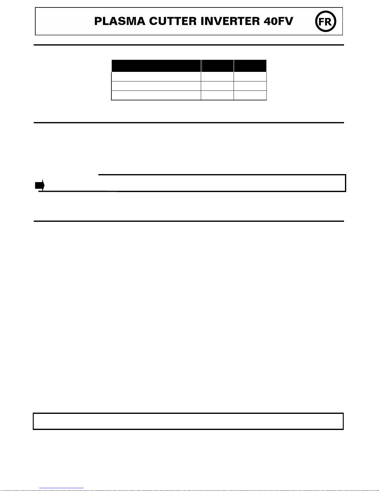
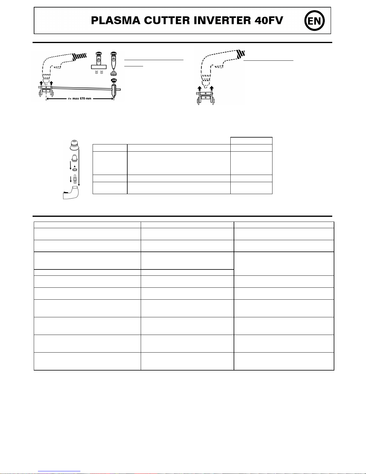
Consommables
V rifier r gulièrement l’ tat d’usure de la buse de protection, de la tuyère et de l’ lectrode ou en cas de r duction
significative de la vitesse de d coupage.
Il est conseill de remplacer en même temps la tuyère et l’ lectrode.
Buse Remplacer si fissur e ou endommag e
040236
Tuyère
Nettoyer si l’int rieur de la tuyère est
obstru ou sale.
Remplacer si l’ouverture est d form e ou si
la taille de l’orifice a augment
040212
Diffuseur Remplacer si les orifices lat raux sont
obstu s
040175
Électrode A remplacer si une cavit importante
apparaît en son centre
040168
Accessoires
ANOMALIES, CAUSES, REMEDES
Anomalies Causes Remèdes
Au d marrage, l’afficheur indique ’Er1’ L’appareil a t mis sous tension avec la
gâchette appuy e Relâcher la gâchette
Au d marrage, l’afficheur indique ’Er2’ Un ou plusieurs boutons du clavier sont
appuy s Relâcher le ou les boutons
Au d marrage, l’afficheur indique ’- - -’ Le poste a t branch sur un r seau
lectrique inadapt (hors plage 85-265V) Contrôler l’installation lectrique ou le
groupe lectrogène
En fonctionnement, l’afficheur indique ’- - -’ Le poste s’est prot g contre une sur-
tension
Le poste ne d livre pas de puissance et le
voyant (3) est allum
La protection thermique du poste s’est
d clench e
Attendre la fin de la p riode de
refroidissement
Le poste ne d livre pas de puissance et le
voyant (4) est allum La buse de la torche n’est pas en place Eteindre le produit, remonter les
consommables, rallumer le poste
l’afficheur indique ’no Air’ La pression d’air est beaucoup trop basse V rifier que l’air soit bien raccord au
produit, r gler la pression d’air
Le poste ne d livre pas de puissance et
l’afficheur indique ‘Er3’
Pas de contact entre l’ lectrode et la
tuyère
Eteindre le produit, v rifier les
consommables, v rifier que l’ lectrode se
r tracte te revient en place facilement.
Essayer de nouveau.
Le poste ne d livre pas de puissance et
l’afficheur indique ‘Er4’ L’ lectrode n’arrive pas à se r tracter
Eteindre le produit, v rifier que l’ lectrode
se r tracte et revient en place facilement.
Essayer de nouveau
L’afficheur indique ’Er5’ Le cycle de d coupe s’est arrêt
anormalement
Eteindre le produit, attendue que l’afficheur
soit teint, r essayer de nouveau. Si l’erreur
persiste renvoyer le produit pour diagnostic
CONDITIONS DE GARANTIE FRANCE
La garantie couvre tout d faut ou vice de fabrication pendant 1 an, à compter de la date d’achat (pièces et main d’œuvre). La
garantie ne couvre pas les erreurs de tension, incidents dus à un mauvais usage, chute, d montage ou toute autre avarie due
au transport.
La garantie ne couvre pas l’usure normale des pièces (Ex. : câbles, pinces, etc.).
En cas de panne, retournez l’appareil à la soci t JBDC (port dû refus ), en y joignant :
- Un justificatif d’achat dat (ticket de caisse ou facture).
- Une note explicative de la panne.
Après la garantie, notre SAV assure les réparations après acceptation d’un devis.
Contact SAV : Soci t JBDC-134 Bd des Loges
BP 4159-53941 Saint-Berthevin Cedex
Fax: +33 (0)2 43 01 23 75 - T l: +33 (0)2 43 01 23 68
Kit compas
(ref. 040205)
Pour d coupe circulaire
jusqu’à 134 cm diamètre.
Fourni avec 3 pointes :
aimant , à pointeau,
à visser
Chariot
(
Ref. 040199)
Pour un confort d’utilisation
et être à distance recommand e
afin d’optimiser les performances
de d coupe et am liorer la dur e
de vie des tuyères.

6
DESCRIPTION
Thank you for choosing our product! To get the best of your equipment, please read carefully the following.
The PLASMA CUTTER 40FV is an inverter plasma cutter, portable, single phase, ventilated. It is able to cut in direct
current (DC) steel, stainless steel, aluminium, copper.
POWER SUPPLY – START UP
•This machine is delivered with a 16A plug type EEC7/7 and integrates a « Flexible Voltage » system. It has to be on a
power suply variable between 85V and 265V (50 – 60 Hz) WITH earth. The absorbed effective current (I1eff) is
shown on the machine, for maximal using conditions. Check that the main supply and its protections (fuse and/or
circuit breaker) are compatible with the required current in use.
•This Class A equipment is intended for use in residential locations where the electrical power is provided by the public
medium- or high-voltage supply system. It is not intended for use in residential locations where the electrical power is
provided by the public low-voltage supply system. There may be potential difficulties in ensuring electromagnetic
compatibility in those locations, due to conducted as well as radiated disturbances.
•These materials do not comply with IEC 61000-3-12. If it is connected to a public low voltage system, it is the
responsibility of the installer or user of the equipment to ensure, by consultation with the distribution network
operator if necessary, that the equipment may be connected.
•Do not use the machine in an area containing metallic conducting dust.
GETTING STARTED (see table and graph on page 2)
•Connect the regulator, and the pneumatic tip for the mahine.
•Connect the unit to the electricity and air supply.
•Turn on the power switch at the back of the machine.
• Connect the earth clamp to a clear area of the workpiece.
• Adjust the pressure.
• Choose the sheet metal or metal mesh mode with the mode adjustment button (8).
• Adjust the cutting current with the adjustment buttons (2).
• Start cutting.
CUTTING MODE (see the graphical interface page 2)
Sheet metal mode :
Choose this mode if cutting metal that is not perforated.
Cutting can be stopped in 2 ways
oBy releasing the trigger.
oWhen the arc no longer meets the metal workpiece.
Metal Mesh mode :
Choose this mode when cutting perforated metal. This mode ensures a continuous arc, even if passed over
holes.
Stop cutting by releasing the trigger, or will stop automatically after 3 seconds without encountering metal.
During either the cutting phase, or torch cooling phase, if the air pressure goes above/below the recommended range
the warning LED (5) flashes. This is to warn the user that the air pressure is outside of optimum level.
SETTING UP THE PRESSURE (see table and graph page 2)
Air Pressure Measurement mode (integrated pressure gauge) :
When this mode is selected, the display shows the current air pressure, bar or PSI.
Press and hold the change mode button (8) to select the unit of measurement.
To start measuring, briefly press the trigger, the air comes out of the torch and the pressure is displayed
followed by a letter "b" for bar or "p" for PSI.
Use the adjustment knob on the air regulator to reach the desired value.
oIf the pressure is too low or too high the display will flash.
If the pressure is too low "no air" appears.
To exit the air measurement mode, briefly press the trigger or the change mode button (8)
Set the current depending on the type and thickness of cutting metal. (see graph on page 2)

7
DUTY CYCLE
The machine described has an output characteristic of 'constant current' type. The duty cycle are indicated in the table
below according to EN60974-1 Norm.
X / 60974-1 @ 40°C
(T cycle = 10 min)
PLASMA 40FV
(230V)
PLASMA 40FV
(110V)
I max 36% at 40A 43% at 40A
60% (T cycle = 10 min) 30 A 25 A
100% (Tcycle = 10 min) 25 A 20 A
Note: the running hot tests have been carried out at atmosphere temperature and duty cycle has been determined at
40°C by simulation.
MAINTENANCE
•Refer all servicing to qualified personnel.
•Disconnect the generator and wait until the ventilator stopped before working on the unit. Inside the device,
voltages and current are dangerous.
•We suggest removing the steel cover 2 or 3 times a year and remove any excess dust. Let check the electrical
connections (with an insulated tool) and the insulations by qualified personnel.
•Regularly control the state of the cord. If this supply cable is damaged, it must be replaced by the manufacturer,
its after sales service or a similarly qualified technician to avoid any danger.
ADVICE
•Leave the inlets free to allow in/out air circulation.
SECURITY
Cutting can be dangerous and lead to serious or e en fatal injuries. Protect yourself and protect the
others.
Respect the following warnings:
Arc rays : Protect yourself thanks to a welding helmet in compliance with EN175 equiped with filters in
compliance with EN 169 or EN 379. Inform and protect by the same means any people in the
welding environment.
Rain, steam, The working environment must be clean (degree of pollution ≤ 3) and protected
humidity : against rain. Put the appliance on an even place and at least at one meter from the parts to
be cut. Do not use them under rain or snow.
Electric shocks : This appliance may only be use with a 230V monophase supply and must be earthed.
Mo ing : Do not underestimate the weight of the apparatus. Do not carry it over people or things. Do
not drop it. Do not set it brutally
Burns : Wear protective or fire-proof clothing (overalls, jeans).
Use some welder gloves and a fire-proof apron.
Protect the others by installing non flammable protection wall, or prevent the
others from looking at the arc and make them keep a sufficient distance
Fire risks: Suppress all flammable products from the working area. Do not work near flammable gas.
Smokes: Do not inhale gas or welding smokes. If indoors ventilate the area well and/or use local
extraction ventilation equipment to remove fumes and gases.
Extraprecautions: Any cutting operation:
- in environments with increased risk of electric shock,
- in confined spaces,
- in the presence of flammable or explosive materials
must be evaluated in advance by an “Expert supervisor” and must always be carried out in the
presence of other people trained to intervene in case of emergency.
Technical protection measures MUST BE taken as described in the TECHNICAL
SPECIFICATION "IEC 62081".
Cutting in raised positions is forbidden unless safety platforms are used.
The persons carrying pacemaker ha e to consult a doctor before using these machines.

8
ACCESSORIES AND CONSUMABLES
Accessories
Consumables
Regularly check the wear condition of the protective tip, nozzle and electrode or in case of significant reduce of the
cutting speed.
It is advised to replace at the same time the nozzle and the electrode.
Plasma 40FV
Tip Replace if cracked or damaged
040236
Nozzle
Clean if the inside of the nozzle is blocked or
dirty.
Replace if the opening is deformed or if the
size of the orifice has half increased.
040212
Diffuser Replace if lateral orifices are bolcked.
040175
Electrode To replace: if a significant cavity appears at
the electrode center.
040168
TROUBLESHOOTING
Anomalies Causes Remedies
At startup, the display shows ’Er1’ The device was turned on with the
trigger pressed Release the trigger
At startup, the display shows ’Er2’ One or more buttons on the keypad are
pressed Release the button(s)
At startup, the display shows ’- - -’
The machine is connected to an
unsuitable power supply (out of 85-265V
range) Check the electrical system or generator
In operation, the display shows ’- - -’ The overvoltage protection is active.
The machine delivers no power and the
indicator (3) is on
The thermal protection of the Plasma
Cutter is active Wait until the end of the cooling phase
The machine delivers no power and the
indicator (4) is on The torch nozzle is not in place Turn off the machine, check and replace the
consumables, turn on the machine
The display shows ’no Air’ The air pressure is too low
Check that the air supply is properly
connected to the machine, adjust the air
pressure
The machine delivers no power and the display
shows ‘Er3’
No contact between the electrode and
the nozzle
Turn off the product, check the
consummables, check the electrode retracts
and returns easily. Try again.
The machine delivers no power and the display
shows ‘Er4’ The electrode cannot retract
Turn off the product, make sure that the
electrode can retract and return easily. Try
again
The display shows ’Er5’ The cutting cycle has stopped abnormally
Turn off the product, wait until the error
disappears, try again. If the error persists
return the product for inspection
Compass divider kit
(ref.
040205)
For circular cutting up to
134 cm diameter.
Provided with 3 axes:
magnetic, with center pin,
with thread
Trolley
(
Ref. 040199)
For a comfortable use and be
at the advised height
For optimizing the cutting
performances and increase
the nozzles life-time.

9
BESCHREIBUNG
Wir freuen uns, dass Sie sich für ein Markengerät der Firma JBDC entschieden haben und danken Ihnen für das
entgegengebrachte Vertrauen. Um das Gerät optimal nutzen zu können, lesen Sie bitte die Betriebsanleitung sorgfältig
durch:
Der PLASMA CUTTER 40FV ist ein einphasiger, ventilgekühlter Druckluft- Plasmaschneider, der sich zum Schneiden von
qualitativ hochwertigem Stahl, Inox, Alu und Kupfer eignet.
NETZANSCHLUSS - INBETRIEBNAHME
•Die Geräte werden mit einem 16A Schuko-Stecker geliefert und dank der Flexible Voltage Technologie ist die
Benutzung in jedem Spannungsnetz zwischen 85V bis 265V (50-60Hz) möglich. Die angegebene Einschaltdauer
bezieht sich auf ein 230V/16A Netz. In anderen Netzen kann die maximale Leistung variieren.
(Achtung: Die gegebenfalls nötigen Umbaumaßnahmen an der Zuleitung dürfen nur von autorisiertem
Fachpersonal durchgefuhrt werden!)
•Dieses JBDC Gerät ist ein Gerät der Klasse A und eignet sich für den industriellen und/oder professionellen
Gebrauch. In einem anderen Umfeld ist die elektromagnetische Verträglichkeit schwieriger zu gewährleisten.
•Dieses Gerät entspricht nicht der Richtlinie CEI 61000-3-12. Es liegt in Ihrer Verantwortung zu überprüfen, ob das
Gerät für den Stromanschluss geeignet ist, bevor Sie es an das Netz anschließen. Bei Fragen wenden Sie sich bitte
an den zuständigen Versorgungsnetzbetreiber.
•Verwenden Sie das Gerät nicht in Räumen, in denen sich metallische Staubpartikel in der Luft befinden, die
Elektrizität leiten konnen.
INBETRIEBNAHME (siehe Interface Seite 2)
•Schliesen Sie das Gerät an 230 V Netzspannung an, Sie benötigen eine externe Druckluftversorgung.
•Schließen Sie das Gerät mit einem passenden Druckluftanschluss an den Druckluftregler an.
•Schalten Sie das Gerät mit dem Ein/Aus-Schalter ein, der sich hinten am Gerät befindet.
•Verbinden Sie die Masseklemme mit dem zu schneidenden Teil.
•Stellen Sie den Druckluftregler ein
•Wählen Sie die Betriebsart: Vollblech oder Gitter mit dem Modus-Einstellknopf (8).
•Stellen Sie mit dem Einstellknopf den Schneidstrom ein (2).
•Schneiden
SCHNEIDE-MODUS (siehe Interface Seite 2)
Vollblech-Modus :
Wählen Sie diesen Modus bei massiven Blechen.
Der Schneidevorgang wird unterbrochen:
owenn der Brennertaster/Auslöser losgelassen wird.
owenn der Kontakt zwischen Lichtbogen und Schneidteil unterbrochen ist.
Gitter-Modus :
Wählen Sie diesen Modus bei gelochten Blechen – sowie Gittern. Dieser Modus ermöglicht ein Zünden des
Lichtbogens wenn kein Kontakt mit dem Schneidteil besteht.
Der Schneidevorgang hört auf bei Loslassen des Brennertasters oder nach 3 Sekunden ohne Kontakt mit dem
Schneidteil.
Während der Schneid- und Abkühlphase des Brenners warnt die Warnleuchte (5) bei falsch eingestelltem Luftdruck.
DRUCKLUFTREGLER (siehe Interface Seite 2)
Druckluftregler-Modus (integrierter Druckminderer) :
Bei Auswahl dieses Modus: die Digital-Anzeige weißt auf die benutzte Druckeinheit - Bar oder PSI hin.
Längerer Druck auf den Modus-Knopf (8) erlaubt die Auswahl der Druckeinheit.
Für das Einstellen des Luftdrucks drücken Sie kurz auf den Brennertaster/Auslöser, es strömt Luft aus dem
Brenner und der Druck wird angezeigt: « b » für Bar und « p » für PSI.
Drehen Sie den Druckluftregler um den gewünschten Wert einzustellen.
oBei zu geringem oder hohem Luftdruck blinkt die Digital-Anzeige.
oBei einem zu niedrigen Luftdruck zeigt die Digital-Anzeige « no air » an.
Um den Druckregler-Modus zu beenden drücken Sie kurz auf den Brennertaster/Auslöser oder auf den
Modus-Einstellknopfknopf (8).
Stellen Sie den Strom und die Schneidegeschwindigkeit je nach Typ und Dicke des zu schneidenden Materials
ein. (siehe Grafik Seite 2)

10
EINSCHALTDAUER
Die JBDC Geräte entsprechen in ihrer Charakteristik einer Gleichstromquelle. Die Einschaltdauer entspricht wie unten
beschrieben der Norm EN 60974-1 (bei 40°C und einem 10 min Zyklus):
X / 60974-1 @ 40°C
(T cycle = 10 min)
PLASMA 40FV
(230V)
PLASMA 40FV
(110V)
I max 36% @ 40A 43% @ 40A
60% (T cycle = 10 min) 30 A 25 A
100% (Tcycle = 10 min) 25 A 20 A
$
N.B. Der Überhitzungstest wurde bei Raumtemperatur durchgeführt und die Einschaltdauer bei 40°C durch Simulation
ermittelt.
INSTANDHALTUNG
•Die Instandhaltungsarbeiten dürfen nur von qualifiziertem Fachpersonal durchgeführt werden.
•Nehmen Sie regelmäßig (mindestens 2 bis 3 Mal im Jahr) das Gehäuse ab und reinigen Sie das Innere des Gerätes
mit Pressluft. Lassen Sie regelmäßig Prüfungen des JBDC Geräts auf seine elektrische Betriebssicherheit von
qualifiziertem Fachpersonal durchführen.
•Trennen Sie vor dem Öffnen des JBDC Gerätes die Stromversorgung zum Gerät und warten Sie bis der Ventilator sich
nicht mehr dreht. Im Gerät sind die Spannungen sehr hoch und deshalb gefährlich.
•Prüfen Sie regelmäßig den Zustand der Netzzuleitung. Wenn diese beschädigt ist, muss sie durch den Hersteller,
seinen Reparaturservice oder eine qualifizierte Person ausgetauscht werden, um Gefahren zu vermeiden.
•Lüftungsschlitze nicht bedecken.
UNFALLPÄVENTION
Lichtbogenschweißen kann gefährlich sein und zu schweren - unter Umständen auch tödlichen -
Verletzungen führen. Schützen Sie daher sich selbst und andere. Beachten Sie unbedingt die folgenden
Sicherheitshinweise:
Lichtbogenstrahlung: Gesichtshaut und Augen sind durch ausreichend dimensionierte EN 175 konforme
Schutzschirme mit Spezialschutzgläsern nach EN 169 / 379 vor der intensiven
Ultraviolettstrahlung zu schützen.
Auch in der Nähe des Lichtbogens befindliche Personen oder Helfer müssen auf Gefahren
hingewiesen und mit den nötigen Schutzmitteln ausgerüstet werden.
Umgebung: Benutzen Sie das Gerät nur in sauberer und gegen Nässeeinwirkung geschützter Umgebung.
Feuchtigkeit: Nicht bei erhöhter Feuchtigkeit (Regen/Schnee) benutzen.
Strom ersorgung: Dieses Gerät kann nur an einer einphasigen Stromversorgung mit 3 Adern (Phase, Nullleiter
und Erde) verwendet werden. Keine Spannungsführenden Teile berühren. Nur am 230 V-Netz
betreiben.
Transport: Unterschätzen Sie nicht das Gewicht der Anlage. Bewegen Sie das Gerät nicht über Personen
oder Sachen hinweg, und lassen Sie es nicht herunterfallen oder hart aufsetzen.
Verbrennungsgefahr: Schützen Sie sich durch geeignete trockene Schweißerkleidung (Schürze, Handschuhe,
Kopfbedeckung sowie feste Schuhe). Tragen Sie auch die Schutzbrille, wenn Sie Schlacke
abklopfen. Schützen Sie andere durch nicht entzündbare Trennwände. Nicht in den Lichtbogen
schauen und ausreichende Distanz halten.
Brandgefahr: Entfernen Sie alle entflammbaren Produkte vom Schweißplatz und arbeiten Sie nicht in der
Nähe von brennbaren Stoffen und Gasen.
Schweißrauch: Die beim Schweißen entstehenden Gase und Rauche sind gesundheitsschädlich! Der
Arbeitsplatz sollte daher gut belüftet sein und der entstehende Rauch und die Gase abgesaugt
werden.
Weitere Führen Sie Schweißarbeiten
Vorsichtsmaßnahmen: - in Bereichen mit erhöhten elektrischen Risiken,
- in abgeschlossenen Räumen,
- in der Umgebung von entflammbaren oder explosiven Produkten
nur in Anwesenheit von qualifiziertem Rettungs- und/oder Fachpersonal durch. Treffen Sie
Vorsichtsmaßnahmen in Übereinstimmung mit "IEC 62081". Schweißarbeiten an
Gegenständen in erhöhter Position dürfen nur auf professionell aufgebauten Gerüsten
durchgeführt werden.
Halten Sie beim Arbeiten ausreichend Abstand zu Personen mit Herzschrittmacher!
Personen mit Herzschrittmacher dürfen mit dem Gerät nicht ohne ärztliche Zustimmung arbeiten!

11
ZUBEHÖR UND VERSCHLEISSTEILE
Zubehör
Verschleißteile
Überprüfen Sie regelmäßig den Verschleißgrad des Schutzrohres, der Düse und Elektrode und verringern Sie bei zu
hohem Verschliss die Schneidegeschwindigkeit.
Ist es dennoch nötig die Verschleißteile auszutauschen, wird empfohlen Düse und Elektrode gleichzeitig auszubauen.
Plasma 40FV
Düse Ersetzen Sie die Düse, wenn diese
abgenutzt oder beschädigt ist.
040236
Schneiddüse
Säubern Sie die Schneiddüse, wenn sie
verstopft oder verschmutzt ist.
Ersetzen Sie sie, wenn die Öffnung
verformt ist oder sich um die Hälfte
vergrößert hat.
040212
Diffusor Ersetzen Sie den Diffusor, wenn die
seitlichen Öffnungen verstopft sind.
040175
Elektrode Ersetzen Sie die Elektrode, wenn sich in der
Mitte ein Hohlraum ausgebildet hat.
040168
FEHLERSUCHE
Fehler Ursache Lösungen
Die Digital-Anzeige zeigt ’Er1’ an Das Gerät wurde mit einem Druck auf
den Brennertaster/Auslöser eingeschaltet
Lassen Sie den Auslöser los
Die Digital-Anzeige zeigt ’Er2’ an Ein oder mehrere Knöpfe der Tastatur
wurden gedrückt Lassen Sie den oder die Knöpfe los
Beim Start zeigt die Digital-Anzeige ’- - -’ an
Das Gerät wurde an einen
falschen
Netzsanschluss angeschlossen (kein 85-
265V) Elektrische Installation oder Generator
überprüfen
Im Betrieb zeigt die Digital-Anzeige ’- - -’ an Der Überspannungsschutz hat das Gerät
abgeschaltet
Das Gerät liefert keinen Strom. Zudem leuchtet
die Anzeige (3).
Der Überhitzungsschutz des Gerätes
wurde ausgelöst
Warten Sie bis sich das Gerät wieder
abgekühlt hat.
Der Lichtbogen zündet nicht und die
Anzeigeleuchte (4) leuchtet.
Die Brenner-Düse ist entweder falsch
montiert worden oder nicht gut
festgeschraubt
Schalten Sie das Gerät aus, die
Verschleißteile wieder montieren, das Gerät
wieder einschalten.
Die Digital-Anzeige zeigt ’no Air’ an Der Luftdruck ist zu niedrig
Überprüfen Sie die Verbingung zwischen die
Druckluftzufuhr und dem Gerät, stellen Sie
den Druckregler ein.
Der Lichtbogen zündet nicht und
die Digital-Anzeige zeigt ‘Er3’ an
Kein Kontakt zwischen Schneidedüse und
Elektrode
Schalten Sie das Gerät aus, überprüfen Sie
die Verschleißteile, überprüfen Sie den Sitz
und die Beweglichkeit der Elektrode. Diese
Aktion wiederholen.
Der Lichtbogen zündet nicht und
die Digital-Anzeige zeigt ‘Er4’ an Die Elektrode ist nicht beweglich.
Schalten Sie das Gerät aus, überprüfen Sie
den Sitz und die Beweglichkeit der
Elektrode. Diese Aktion wiederholen.
Die Digital-Anzeige zeigt ‘Er5’ an Der Schneide-Vorgang wurde
unterbrochen.
Schalten Sie das Gerät aus, warten Sie bis
das Gerät ausgeschaltet ist, wiederholen Sie
den Vorgang. Wenn der Fehler nicht
behoben ist, schicken Sie das Gerät zurück
zur Diagnose.
Kit Kompass
(Art-Nr. 040205)
Kreisausschnitte bis zu einem
Durchmesser von 134 cm
möglich. Wird mit 3
Verbindungmöglichkeiten
geliefert: Magnetisch, mit
Mittelbolzen, zum
Verschrauben
Wagen
(Art-Nr. 040199)
Ermöglicht eine bequemere
Handhabung des Gerätes (Sie
können auf der vom Hersteller
empfohlenen Höhe arbeiten).
Optimierung der Schnittleistung
und Verlängerung der Haltbarkeit
der Düsen

12
DESCRIPCION
Gracias por su elección ! Para sacar el mayor provecho de su máquina, lea atentamente lo siguiente :
El PLASMA CUTTER 40FV es máquina de corte plasma Inverter, portatil, monofásica, ventilada. Permite cortar en
corriente continua (DC) los aceros, inox, aluminio, cobre. Son protegidos para funcionar con grupos electrógenos.
ALIMENTACION – PUESTA EN MARCHA
•Estos aparatos se venden con un enchufe 16A tipo EEC7/7. La máquina debe conectarse a una red el ctrica incluida
entre 85 y 265V (50-60 Hz) con conexión tierra, y es protegido para funcionar con grupos electrógenos. La corriente
efectivamente absorbida (l1eff) está indicada sobre la máquina para las condiciones de uso máximas. Comprobar que
la alimentación y su protección (fusible o disyuntor) son compatibles con la corriente que requiere la utilización.
•Este aparato es de Clase A. Fue concebido para un uso en un ambiente industrial o profesional. En un entorno
distinto, puede ser difícil asegurar la compatibilidad electromagn tica, a causa de perturbaciones conducidas tan bien
como radiadas. No utilizar en un entorno con polvos metálicos conductores. Este equipo no respeta la CEI 61000-3-
12. Si se dedica a conectarse al sistema público de alimentación de baja tensión, es de la responsabilidad del usuario
de asegurarse que pueden conectarse a ste. Si es necesario, consultar al operador de su red de alimentación
el ctrica.
•No utilizar en un lugar donde hay polvo metálico que conduce la electricidad.
PUESTA EN MARCHA ( er interfaz página 2)
•Conectar el equipo a la red electrica y a la red de aire comprimido. Previamente, colocar, sobre el filtro regulador, la
boquilla de conexión neumatica adecuada para su instalación.
• Poner en marcha el equipo gracias al conmutador situado detrás del equipo.
• Conectar la pinza de masa sobre la zona perfectamente pulida de la pieza que soldar.
• Ajustar la presión.
• Elegir el modo chapa llena o chapa tipo ‘rejilla’ gracias a la tecla modo (8).
• Ajustar la corriente de corte gracias a las teclas de reglaje (2).
• Cortar.
MODO DE CORTE ( er interfaz página 2)
Modo chapa llena :
Elegir este modo cuando la chapa no está calada.
El corte puede pararse de 2 maneras :
oAl relajar el gatillo.
oCuando el arco no encuentra más el metal que cortar.
Modo chapa tipo ‘rejilla’ :
Elegir este modo cuando la chapa que cortar está calada. Este modo permite mantener el arco cebado aún si
ste conduce a un vacio.
El corte se para al relajar el gatillo o al cabo de 3 segundos sin encontrar metal.
Durante la fase de corte o de refrigeración de la antorcha, si la presión de aire sal del margen recomendado, el piloto
(5) parpadea. Advierte al usuario que la presión utilizada no está óptima.
RÉGLAJE DE LA PRESIÓN ( er interfaz página 2)
Modo medida de aire (manometro integrado) :
Cuando este modo está seleccionado, la pantalla indica la unidad de presión utilizada, bar o PSI.
Una presión prolongada sobre la tecla modo (8) permite elegir la unidad de medida.
Para iniciar la medida, apretar brevemente el gatillo, el aire sale de la antorcha y la presión aparece en la
pantalla, seguida por una letra « b » por bar y « p » por PSI.
Girar la rueda del regulador de presión para ajustar el valor deseado.
oSi la presión es demasiado baja o demasiado elevada, la pantalla parpadea.
oSi la presión es aún demasiado baja, « no aire » aparece.
Para salir del modo medida de aire, apretar brevemente el gatillo o la tecla modo (8).
Arreglar la corriente según el tipo y el espesor del metal que cortar. (ver gráfico página 2)

13
FACTORES DE FUNCIONAMIENTO
Los aparatos descritos tienen una característica de salida de tipo "corriente constante". Sus factores de funcionamiento,
según la norma EN60974-1 están indicados en la tabla siguiente :
X / 60974-1 @ 40°C
(T cycle = 10 min)
PLASMA 40FV
(230V)
PLASMA 40FV
(110V)
I max 36% @ 40A 43% @ 40A
60% (T cycle = 10 min) 30 A 25 A
100% (Tcycle = 10 min) 25 A 20 A
Nota: las pruebas de calentamiento fueron realizadas con una temperatura ambiente y el factor de funcionamiento a
40°C fue determinado por simulación.
MANTENIMIENTO
•El mantenimiento sólo debe ser hecho por una persona calificada
•Cuidado con apagar el generador y esperar la parada del ventilador. En efecto, las tensiones y intensidades son
elevadas y peligrosas.
•Es recomendado 2 a 3 veces al año quitar la tapa y desempolvar con una pistola de aire comprimido. Aprovechar la
ocasión para comprobar las conexiones el ctricas con un instrumento isolado.
•Controlar regularmente el estado del cable de alimentación. Si esta dañado, es necesario cambiarlo por el fabricante,
por su servicio post-venta o por una persona de calificación similar, para evitar cualquier peligro.
NUESTROS CONSEJOS
•Dejar las persianas libres para la entrada y la salida de aire.
SEGURIDAD
La soldadura al arco puede ser pelígrosa y causar heridas gra es o mortales. Protega usted y protega a los
demas.
Tome sus precauciones contra:
Radiación del arco: proteg se por una pantilla, con filtras conformes EN 169 o EN 379.
Llu ia importante, Utilizar el aparato preferentemente en una atmósfera limpia (graduación de contaminación≤ 3),
apor de agua de plano y a más de un metro de la pieza a soldar
, humedad. Utilización prohibida con lluvia o nieve
Choque eléctrico : Este aparato sólo debe ser utilizado con una alimentación monofásica de 3 alambres con neutro
conectado a la tierra. No tocar las piezas bajo tensión. Comprobar que la red de alimentación
corresponda al aparato.
Caídas : No desplazar el aparato por encima de personas u objetos.
Quemaduras : Llevar trajes de trabajo ignifugados (cotón, mono o jeans).
Trabajar con guantes de protección y un mandil ignifugado.
Protega a los demas instalando biombos ininflamables, o previ ndoles de no mirar al arco y
quedarse sufisacientemente lejos de la zona de corte
Riesgo de fuego : Suprimir todos los productos inflamables del espacio de trabajo. Nunca trabajar cerca de gas
inflamable.
Humos : Nunca inhalar humos y gas de soldadura, utilizar en un entorno correctamente ventilado o / y
con una extracción artificial si la soldadura está realizada adentro.
Precauciones :
Cualquier obra de soldadura :
Adicionales - en lugares que presentan riesgos de choque el ctrico,
- en lugares cerrados
- en presencia de materiales inflamables o que presentan riesgos de explosión, siempre
deben ser sumisos a una previa aprobación de un "responsable experto" y realizada en
presencia de personas formadas para intervenir en caso de urgencia.
Los medios t cnicos de protección descritos en la "ESPECIFICACION TECNICA CEI/IEC 62081"
deben ser aplicados.
Soldar en posición sobrealzada está prohibido, excepto sobre plataformas de securidad.
Las personas que lle an un estimulador cardíaco deben consultar su médico antes
de utilizar estos aparatos

14
ACCESORIOS Y CONSUMIBLES
Accesorios
Consumibles
Regularmente, comprobar el estado de desgaste del tubo de protección, de la tobera y del electrodo o en caso de
reducción significativa de la velocidad de corte.
Es fuertemente recomendado remplazar a la vez la tobera y el electrodo.
Plasma 40FV
Tubo Remplazar en caso de fisura o de daño
040236
Tobera
Limpiar si su interior está obstruido o sucio
Remplazar si el hueco está deformado o si el
tamaño del orificio ha aumentado de mitad.
040212
Difusor Remplazar si los orificios laterales están
obstruidos.
040175
Electrodo Replazar si se nota una cavidad importante
en su centro.
040168
ANOMALÍAS, CAUSAS, REMEDIOS
Anomalías Causas Remedios
Al arranque, la pantalla indica ’Er1’ El equipo se enciende al apretar el gatillo
Relajar el gatillo
Al arranque, la pantalla indica ’Er2’ Una o 2 teclas del teclado quedan
apretadas Relajar la o las teclas
Al arranque, la pantalla indica ’- - -’
El equipo está conectado con una red
electrica inadecuada (fuera de rango 85-
265V) Comprobar la instalación electrica o el grupo
electrogeno
Al funcionar, la pantalla indica ’- - -’ El equipo se ha protegido contra una
sobretensión
El equipo no libera potencia y el
indicador (3) está encendido
La protección t rmica del aparato
se ha puesto en marcha
Esperar el fin del tiempo de
enfriamiento
El equipo no libera potencia y la pantalla (4)
está encendida
La boquilla de la antorcha no está bien
colocada
Apagar el equipo, reponer correctamente los
consumibles, encender de nuevo el equipo
La pantalla indica ’no Aire’ La presión de aire está demasiado baja Comprobar que el aire est bien conectado
al equipo, ajustar la presión de aire.
El equipo no libera potencia y la pantalla indica
‘Er3’
No hay contacto entre el electrodo y la
tobera
Apagar el equipo, comprobar los
consumibles, comprobar que el electrodo se
retraya y vuelve fácilmente en su sitio.
Intentar otra vez
El equipo no libera potencia y la pantalla indica
‘Er4’ El electrodo no puede retraerse
Apagar el equipo, comprobar que el
electrodo se retraya y vuelve fácilmente en
su sitio. Intentar otra vez
La pantalla indica ’Er5’ El ciclo de corte se ha parado
anormalmente
Apagar el equipo, esperar que la pantalla se
apague, intentar otra vez. Si el error
persiste, devolver el producto a su vendedor
para diagnostico
Kit compas
(ref. 040205)
Para un corte circular
hasta 134 cm de diámetro.
Entregado con 3 ejes:
Inmantado, de aguja, de
atornillar
Carrito
(
Ref. 040199)
Para una utilización comoda
Para quedarse a distancia recomendada
para optimizar los resultados de corte y
aumentar la duración de vida de las
toberas.

15
ОПИСАНИЕ
Мы благодарим Вас за то, что вы выбрали аппарат нашей марки. Чтобы полностью использовать его
возможности, пожалуйста ознакомьтесь с данной инструкцией.
PLASMA CUTTER 40FV является аппаратом плазменной резки инверторного типа, переносные, однофазные,
вентилируемые. Он защищен для работы от электрогенератора.
ПИТАНИЕ – ВКЛЮЧЕНИЕ
•Данный аппарат поставляется с 16А- ой вилкой, типа CEE 7/7. Онащен системой « Flexible Voltage », он
питатется от розетки с ЗАЗЕМЛЕНИЕМ на 85В и 265В (50 - 60 Гц). Он защищен для работы от
электрогенератора. Количество реально потребляемой энергии (I1eff) при интенсивном использования,
указано на аппарате. Проверьте совместимость электрического питания и его защит (предохранитель и/или
авт. выключатель) с электрическим током, необходимым для работы аппарата.
•Этот аппарат относится к Классу A. Он создан для использования в промышленной и профессиональной
среде. В любой другой среде ему будет сложно обеспечить электромагнитную совместимость из-за
кондуктивных и индуктивных помех. Это оборудование не соответствует CEI 61000-3-12. Аппараты должны
быть подключены к общественной системе питания низкого напряжения, пользователь должен
удостовериться, что аппарат может быть подключен в сеть. При необходимости проконсультируйтесь у вашего
энергосистемного оператора.
•Не использовать в среде содержащей металлическую пыль-проводник.
ЗАПУСК В РАБОТУ (см дисплей стр.2)
•Подключите аппарат к электричеству и подаче воздуха. Предварительно подключите на фильтр-регулятор
насадку пневматического подключения адаптированную для вашей установки.
• Включите аппарат с помощью коммутатора находящегося на тыльной панели аппарата.
• Подключите зажим массы к зачищенной зоне свариваемой детали.
• Отрегулируйте напор воздуха.
• Выберите режим «однородная деталь» или «решетка» с помощью кнопки Режим (Mode) (8).
• Настройте ток резки с помощью регулировочных кнопок (2).
• Можете резать.
РЕЖИМ РЕЗКИ (см дисплей стр.2)
Режим «однородная деталь» :
Выбрать этот режим если лист металла не решетчатый.
Резка может быть остановлена 2-мя способами:
oОтпусканием триггера.
oАвтоматически при прекращении контакта дуги с разрезаемым металлом
Режим «решётчатая металлическая панель» :
Выбрать этот режим, когда панель уже прорезана. Этот режим позволяет сохранить дугу, даже если
она проходит в прозорах решетки.
Резка прекращается при отпускании триггера или при отутствии контакта с металлом в течение 3-х
секунд.
На этапе резки или охлаждения горелки, если напор воздуха выходит за рекомендуемый диапазон, мигает
лампочка (5). Она оповещает пользователя, что напор не оптимален.
РЕГУЛИРОВКА НАПОРА (см. интерфейс на стр.2)
Режим «Измерение напора воздуха» (встроенный манометр) :
В этом режиме дисплей показывает используемую единицу измерения давления, бар или PSI.
Длинное нажатие на кнопку режимов (8) позволяет выбрать единицу измерения.
Чтобы начать измерение, коротко нажмите на триггер, воздух начнет выходить из горелки и давление
будет указано в цифрах, следуемых буквами « b » для бар и « p » для PSI.
Поверните колесико регулятора уровня давления, чтобы настроить желаемую величину.
oЕсли давление слижком низкое или слишком высокое, дисплей начнет мигать.
oЕсли давление критически низкое, то на дисплее появится надпись « no air ».
Чтобы выйти из режима измерения давления, коротко нажмите на триггер, или на кнопку выбора
режима (8).
Отрегулируйте ток в зависимости от типа и толщины вырезаемого металла. (см.график стр.2)

16
ОТНОСИТЕЛЬНАЯ ПРОДОЛЖИТЕЛЬНОСТЬ ВКЛЮЧЕНИЯ, ПВ %
Описанные аппараты имеют выходные характеристики типа 'постоянный ток'. Значения относительной
продолжительности включения (ПВ%), согласно норме EN60974-1, описаны в следующей таблице:
X / 60974-1 @ 40°C
(T cycle = 10 min)
Plasma 40FV
(230V)
Plasma 40FV
(110V)
I max 36% при 40A 43% при 40A
60% (T cycle = 10 min) 30 A 25 A
100% (Tcycle = 10 min) 25 A 20 A
Примечание: нагревные испытания были реализованы при температуре окружающей среды, и ПВ% при 40 °C
был определён методом симуляции.
УХОД И ОБСЛУЖИВАНИЕ
•Обслуживание аппарата должно производиться только квалифицированным персоналом.
•Всегда сначала отключите аппарат от сети, затем дождитесь остановки вентилятора. Только тогда вы можете
работать над аппаратом. Токи и напряжения внутри аппарата значительны и представляют опасность.
•Регулярно, 2-3 раза в год, снимайте крышку аппарата и очищайте его от пыли Одновременно обеспечте
проверку контактов соединений квалифицированным специалистом с помощью изолированного инструмента.
•Необходимо проверять регулярно состояние электрического шнура. Если электрический кабель повреждён, то
он должен быть заменён изготовителем, его послепродажным отделом, или квалифицированным персоналом,
во избежание всякого риска.
НАШ СОВЕТ
•Оставьте вентиляционные щели аппарата открытыми для свободной циркуляции воздуха.
ТЕХНИКА БЕЗОПАСНОСТИ
Электродуговая резка может быть опасна для здоровья и жизни.
Защитите себя и окружающих, примите меры безопасности против:
Излучений дуги: защитите себя с помощью маски, снабженной фальтрами, соответствующими нормам
EN 169 или EN 379.
Сильного дождя, Используйте ваш аппарат в чистой атмосфере (уровень загрязнения ≤ 3), на
водяных паров плоской поверхности и не ближе, чем в 1 м от разрезаемой детали.
влажности : Не использовать аппарат под дождём и снегом
Электроудара: данный аппарат должен быть включен в однофазную сеть с заземлением. Не касайтесь
деталей под напряжением. Убедитесь, что используемая вами сеть подходит для
данного аппарата.
Падений: Не переносите аппарат над людьми или объектами.
Ожогов: Надевайте рабочую одежду из плотных материалов (хлопок, джинс, спецодежда).
Работайте в защитных перчатках и несгораемом фартуке.
Защитите окружающих, установив несгораемые ограждения или попросите их не
смотреть на дугу и придерживаться безопасного расстояния.
Пожара : Удалите все воспламеняемые продукты из зоны сварки. Не работайте в среде горючих
газов.
Дыма : Не вдыхайте газы и дым, производимые сваркой. Использовать аппарат в хорошо
проветриваемом помещении, с искуственной вентиляцией, при резке внутри закрытого
помещения.
Дополнительные : Любая работа, связанная с плазменной резкой:
Меры - в помещениях с повышенным риском электрошока,
Предосторожности - в закрытых помещениях
- около восламеняющихся или взрывчатых материалов, всегда должна быть
предварительно подтверждена ответственным специалистом и реализована в
присутствии обученного персонала, для срочного вмешательства в случае
необходимости
Технические меры безопасности, описанные в "Технических Характеристиках" CEI/IEC
62081 должны быть соблюдены. Резка на высоте запрещена. Исключение составляет
использование рабочих площадок безопасности.
Лица, использульзующие электрокардиостимуляторы, должны проконсультироваться у врача
перед работой с данными аппаратами.

17
АКСЕССУАРЫ И РАСХОДНЫЕ МАТЕРИАЛЫ
Аксессуары
Расходные материалы
Регулярно проверяйте состояние износа защитного сопла, насадки и электрода, особенно в случае занчительного
уменьшения скорости резки.
Советуем заменять одновременно насадку и электрод.
Plasma 40FV
Сопло Заменть при наличии трещин и
повреждений
040236
Насадка
Очистить, если насадка внутри грязная
или забита.
Заменить, если отверстие
деформировано или если размер
отверстия увеличился вполовину.
040212
Распылитель Заменить, если боковые отверстия
забиты.
040175
Электрод Заменить, если в центре появилась
значительная выемка
040168
AНОМАЛИИ, ВОЗМОЖНЫЕ ПРИЧИНЫ, ВАРИАНТЫ РЕШЕНИЙ
Аномалия Возможная причина Решение
При запуске, дисплей показывает ’Er1’ Аппарат включили под напряжение
при нажатом триггере. Отпустите триггер
При запуске, дисплей показывает ’Er2’ Одна или несколько кнопок панели
были нажаты. Отпустите одну или несколько кнопок
При запуске, дисплей показывает ’- - -’
Аппарат был подключен к
неподходящей электрической сети
( Вне диапазона 85-265V) Проверьте электропроводку или
электрогенератор
При работе, дисплей показывает ’- - -’ Включилась защита от
перенапряжения.
Аппарат не выдает мощности. Индикатор (3)
горит.
Сработала термическая защита
аппарата.
Подождите окончания периода охлажде-
ния.
Аппарат не выдает мощности и горит
светодиод (4) Сопло на горелке отутствет. Выключите аппарат, присоедините сопло,
заново включите аппарат
Дисплей показывает’no Air’ Напор воздуха слишком низок. Проверьте подвод воздуха к аппарату и
отрегулируйте напор.
Аппарат не выдает мощности и дисплей
показывает ‘Er3’
Отсутствует контакт между
электродом и насадкой
Вылючите аппарат, проверьте
расходники, проверьте, убирается и
возвращается ли на место электрод.
Попробуйте заново.
Аппарат не выдает мощности и дисплей
показывает ‘Er4’ Электрод не убирается
Вылючите аппарат, проверьте, убирается
и возвращается ли на место электрод.
Попробуйте заново.
Дисплей показывает ’Er5’ Цикл резки внезапно прервался
Выключите аппарат, дождитесь, пока
дисплей выключится, поробуйте заново.
Если ошибка повторится, верните аппарат
в сервис на диагностику.
Циркуль в наборе
(арт. 040205)
Для круговой резки диамет-
ром до 134 см. Поставляется
с 3-мя осями: магнитной,
игольчатой и резьбовой
Тележка
(арт
. 040199)
Для удобства в использовании, и
чтобы находиться на
рекомендованном расстоянии для
улучшения качества резки, а также
для увеличения срока службы
насадок.

18
Déclaration de conformité
JBDC atteste que les d coupeurs plasma sont fabriqu s conform ment aux exigences des directives Basse tension
2006/95/CE du 12/12/2006, et aux directives CEM 2004/108/CE du 15/12/2004.
Cette conformit est tablie par le respect des normes harmonis es EN60974-1 de 2005, EN 50445 de 2008, EN
60974-10 de 2007.
Le marquage CE a t appos en 2013.
Declaration of conformity
The equipment described on this manual is conform to the instructions of low voltage 2006/95/CE of 12/12/2006,
and the instructions of CEM 2004/108/CE of the 15/12/2004.
This conformity respects the standards EN60974-1 of 2005, EN 50445 de 2008, EN60974-10 of 2007.
CE marking was added in 2013.
Konformitätserklärung
JBDC erklärt, dass beschriebene Geräte in Übereinstimmung mit den Anforderungen der folgenden europäischen
Bestimmungen: Niederspannungsrichtlinie 2006/95/CE –12.12.2006 und EMV- Richtlinien 2004/108/CE –
15.12.2004 elektromagnetische Verträglichkeit- hergestellt wurden. Diese Geräte stimmen mit den harmonisierten
Normen EN60974-1 von 2005, EN 50445 von 2008, EN60974-10 von 2007 überein.
CE Kennzeichnung: 2013
Declaracion de conformidad
JBDC certifica que los aparatos PLASMA CUTTER 40FV son fabricados en conformidad con las directivas baja
tensión 2006/95/CE del 12/12/2006, y las directivas compatibilidad electromecánica 2004/108/CE del 15/12/2004.
Esta conformidad está establecida por el respeto a las normas EN60974-1 de 2005, EN 50445 de 2008, EN
60974-10 de 2007.
El marcado CE fue fijado en 2013.
Декларация о соответствии
JBDC заявляет, что сварочные аппараты PLASMA CUTTER 40FV произведены в соответствии с директивами
Евросоюза 2006/95/CE о низком напряжении от 12/12/2006, а также с директивами CEМ 2004/108/CE от
15/12/2004.
Данное соответствие установлено в соответствии с согласованными нормами EN 60974-1 2005 г, EN 50445
2008 г, EN 60974-10 2007 г.
Маркировка ЕС нанесенна в 2013 г.
01/07/13 Nicolas BOUYGUES
Société JBDC Pr sident Directeur G n ral
134 BD des Loges
53941 Saint Berthe in
HERSTELLERGARANTIE
Die Garantieleistung des Herstellers erfolgt ausschließlich bei Fabrikations- oder Materialfehlern, die binnen 12
Monate nach Kauf angezeigt werden (Nachweis Kaufbeleg). Nach Anerkenntnis des Garantieanspruchs durch den
Hersteller bzw. seines Beauftragten erfolgen eine für den Käufer kostenlose Reparatur und ein kostenloser Ersatz
von Ersatzteilen. Der Garantiezeitraum bleibt aufgrund erfolgter Garantieleistungen unverändert.
Ausschluss:
Die Garantieleistung erfolgt nicht bei Defekten, die durch unsachgemäßen Gebrauch, Sturz oder harte Stöße
sowie durch nicht autorisierte Reparaturen oder durch Transportschäden, die in Folge des Einsendens zur
Reparatur, hervorgerufen worden sind. Keine Garantie wird für Verschleißteile (z.B. Kabel, Klemmen,
Vorsatzscheiben etc.) sowie bei Gebrauchsspuren übernommen.
Das betreffende Gerät bitte immer mit Kaufbeleg und kurzer Fehlerbeschreibung ausschließlich über den
Fachhandel einschicken. Die Reparatur erfolgt erst nach Erhalt einer schriftlichen Akzeptanz (Unterschrift) des
zuvor vorgelegten Kostenvoranschlags durch den Besteller. Im Fall einer Garantieleistung trägt JBDC
ausschließlich die Kosten für den Rückversand an den Fachhändler.

19
PIÈCES DE RECHANGE - SPARE PARTS - RECAMBIOS - ERSATZTEILE - ЗАПЧАСТИ
N° Désignation Plasma
40FV N° Désignation Plasma
40FV
1
Clavier de commande / Control Keyboard /
Bedienfeld / Teclado de mando / Панель
управления
51951
6d
Carte contrôle / Control board / Steuerplatine /
Carta de mando / Плата управления 97213
2
Poign e / handle / griff / puño / Рукоятка 56014
6e
Ventillateur / Fan / Ventilator / ventilador /
Вентилятор 51021
3
Commutateur / Switch / Spannungsschalter /
Conmutador / переключатель 51075
7
Pieds / feet / Füsse / pies / ножки 71138
4
Cordon secteur / Power cord / Netzzuleitung /
Cordón de alimentación /Сетевой шнур 3 x 1,5
мм²
21494
8
Presse toupe / Cable gland /
Kabeldurchführung / Prensaestopa /
Кабельный ввод
71164
5
Filtre de pression / pressure regulator /
Luftdruckregulator / regulador de presión /
Регулятор давления
71457
9
Connecteur / Connector / Anschlussbuchse /
Conectador / коннектор
51469
6a
Carte puissance (SMI 97512 + 6d) / Power
circuit board / Hauptplatine / carta de potencia
/ силовая плата
Torche / torche / Brenner/ antorcha / Горелка 71520
6b
Carte CEM / EMC board / EMW-Platine / Carta
CEM / Плата СЕМ 97212 Pince de masse / Earth cable / Massekabel /
cable de masa / кабель массы
043787
6c
Carte alimentation / power supply circuit /
Stromversorgungsplatine /Carta de
alimentaciόn / Плата питания
97207
ICONES/SYMBOLS/ ZEICHENERKLÄRUNG
A
Ampères Amps Ampere Amperios
Ампер
V
Volt Volt Volt Voltios Вольт
Hz
Hertz Hertz Hertz Hertz Герц
Coupage plasma Plasma cutting Plasma
Schneiden
Corte plasma Плазменная резка
Convient au d coupage dans un environnement avec risque
accru de choc lectrique. La source de courant elle-même ne
doit toutefois pas être plac e dans de tels locaux.
Adapted for
cutting in environment with increased risks of electrical shock.
However, the current source must not be placed in such places.
Geeignet für Schneidarbeit im Bereich mit erhöhten elektrischen
Risiken. Trotzdem sollte die Stromquelle nicht in solchen Bereichen
betrieben werden
.
Adaptado al corte en un entorno que comprende
riesgos de choque el ctrico. La fuente de corriente ella misma no debe
estar situada dentro de tales locales.
Адаптирован для резки в
среде с повышенным риском электрошока. Однако сам источник
питания не должен быть расположен в таких местах.
IP23
Prot g contre l’accès aux parties dangereuses des
corps solides de diam >12,5mm et chute d’
eau (30%
horizontal)
Protected against access to dangerous
parts by any solid body which Ø > 12,5mm and against
water falls (30% horizontal)
Kontaktschutz zu
gefärlichen Teilen mit Ø > 12,5mm und Schutz gegen
Spritzwasser Einfallwinkel 30%.
Protegido contra el
acceso a la
s partidas peligrosas de cuerpos solidos de
diametro >12.5mm y las caídas de agua (30% horizontal)
Защищен против доступа твердых тел диаметром
>12,5мм к опасным частям и от воды (30% горизонт.)
IP21
Prot g contre l’accès aux parties dangereuses avec un
doigt, et contre les chutes verticales de gouttes d'eau
Protected against rain and against fing
ers access to
dangerous parts
Geschützt gegen Berührung mit
gefährlichen Teilen und gegen senkrechten
Wassertropfenfall
protegido contra el acceso a las
partes peligrosas con los dedos, y contra las caídas
verticales de gotas de agua Аппарат защищен от
доступа рук в опасные зоны и от вертикального
падения капель воды
Ø10 Ø8
71395
71478
1
2
3
4
5
6d
6a
6c
6b
6e
9
7
8
6

20
Alimentation lectrique monophas e 50 ou 60Hz
Single phase power supply 50 or 60Hz Einphasige Netzversorgung mit 50 oder 60Hz Alimentación el ctrica
monofásica 50 o 60 Hz Однофазное напряжение 50 или 60Гц.
Uo Tension assign e à vide Rated no-load voltage Leerlaufspannung Tensión asignada de vacío
Напряжение холостого хода.
U1 Tension assign e d’alimentation rated supply voltage Netzspannung
Tensión de la red Напряжение сети
I1max
Courant d’alimentation assign maximal (valeur efficace) Rated maximum supply current (effective value)
Maximaler Versorgungsstrom (Effektivwert) Corriente maxima de alimentacion de la red
Максимальный сетевой ток (эффективная мощность)
I1eff Courant d’alimentation effectif maximal Maximum effective supply current Maximaler tatsächlicher
Versorgungsstrom Corriente de alimentación efectiva maxima Максимальный эффективный сетевой ток
EN60 974-1
L’appareil respecte la norme EN60974-1 The device complies with EN60974-1 standard relative to welding units
Das Gerät entspricht der Norm EN60974-1 für Schweißgeräte El aparato está conforme a la norma EN60974-1
referente a los aparatos de soldadura Аппарат соответствует европейской норме EN60974-1
Convertisseur monophas transformateur-redresseur Single phase inverter, converter-rectifier Einphasiger
statischer Frequenzumformer/ Trafo/ Gleichrichter Convertidor monofásico transformador-rectificador Однофазный
инвертор, с трансформацией и выпрямлением.
@40°C
X/10
min
…%
X : Facteur de marche à …% X : duty factor at …% X : Einschaltdauer …% X
: Factor de funcionamiento
de …% X : Продолжительность включения …%
% de temps d’utilisation continu jusqu’à disjonction thermique à 20°C ambiant. % of coninuous use time up to
thermal shutdown at 20°C Corresp.
Einschaltdauer unter 20°C % de tiempo en utización continua hasta disyunción t rmica, a 20°C ambientes. %
времени непрерывного использования до срабатывания термозащиты при температуре окружающей среды 20°C.
I2
…%
I2 : courant de soudage conventionnel correspondent I2 : corresponding conventional welding current I2 :
entsprechender Schweißstrom I2 : Corrientes correspondientes I2 : соответствующие условные сварочные токи
U2
…%
U2 : Tensions conventionnelles en charges correspondantes U2 : conventional voltages in corresponding load
U2 : entsprechende Arbeitsspannung U2 : Tensiones convencionales en carga U2 : соответствующие условные
сварочные напряжения
Appareil conforme aux directives europ ennes
The device complies with European Directive
Gerät entspricht europäischen Richtlinien
El aparato está conforme a las normas europeas.
Устройство соответствует европейским нормам.
Conforme aux normes GOST (Russie) Conform to standards GOST / PCT (Russia) in Ubereinstimmung mit der
Norm GOST/PCT
Conforme a la normas GOST (PCT) (Rusia)
Продукт соответствует стандарту России (РСТ)
L’arc lectrique produit des rayons dangereux pour les yeux et la peau (prot gez-vous !)
The electric arc produces
dangerous rays for eyes and skin (protect yourself !) Der elektrische Lichtbogen verursacht Strahlungen auf Auge
n und
Haut (schützen Sie sich !) El arco produce rayos peligrosos para los ojos y la piel (¡ Protegase !)
Электрическая
дуга производит опасные для глаз и кожи лучи (защитите себя!)
Attention, d couper peut d clencher un feu ou une explosion. Caution, cutting can produce fire or explosion.
Achtung : Schweißen kann Feuer oder Explosion verursachen
Cuidado, cortar puede iniciar un fuego o una
explosión. Внимание! Резка может вызвать пожар или взрыв.
Le dispositif de d connexion de s curit est constitu par la prise secteur en coordination avec l'installation lectrique
domestique. L'utilisateur doit s'assurer de l'accessibilit de la prise. The mains disconnection mean is the mains plug in
combination with the house installation. Accessibility of the plug must be guaranteed by user.
Die Stromunterbrechung
erfolgt durch Trennen des Netzsteckers vom häuslichen Stromnetz. Der Gerätanwender sollte den freien Zugang zum
Netzstecker immer gewährleisten El dispositivo de desconección de seguridad se constituye de la toma de la red
electrica en coordinación con la instalación el ctrica dom stica. El usuario debe asegurarse de la accesibilidad del
enchufe. Система отключения безопасности включается через сетевую штепсельную розетку соответствующую
домашней электрической установке. Пользователь должен убедиться, что розетка доступна.
Courant de soudage continu Welding direct current Gleichschweissstrom La corriente de soldadura es
continua Сварка на постоянном токе
Mise en veille/mise en marche standby/On
Standby / Einschalten standby/ puesta en marcha Включить/Режим ожидания
Attention ! Lire le manuel d’instruction avant utilisation Caution ! Read the user manual
Achtung : Lesen Sie die Betriebsanleitung
Cuidado, leer las instrucciones de utilización.
Внимание ! Читайте инструкцию по использованию
Produit faisant l'objet d'une collecte s lective- Ne pas jeter dans une poubelle domestique Separate collection
required – Do not throw in a domestic dustbin Produkt für selektives Einsammeln. Werfen Sie diese Geräte nicht in
die häusliche Mülltonne.
Este aparato es objeto de una recolección selectiva. No debe ser tirado en en cubo dom stico.
Продукт требует специальной утилизации. Не выбрасывать с бытовыми отходами.
Table of contents
Languages:
Other GYS Welding System manuals

GYS
GYS PROTIG 231 DC FV User manual

GYS
GYS TIG 207FV User manual

GYS
GYS GYSMI 80P User manual

GYS
GYS RENOV'POLYCARBONATE User manual

GYS
GYS 70 CT Series User manual

GYS
GYS S39 User manual

GYS
GYS MONOGYS 320-4CS User manual

GYS
GYS PROGYS 180A User manual

GYS
GYS TIG 168DC User manual

GYS
GYS GYSMI 220P User manual

GYS
GYS PROTIG 201 AC/DC User manual

GYS
GYS T3GYS User manual

GYS
GYS GYSPOT 125L Manual

GYS
GYS GYSPOT 100R User manual

GYS
GYS NeoPulse Series User manual

GYS
GYS M1 GYS AUTO User manual

GYS
GYS TIG 168 DC HF User manual

GYS
GYS Easymig 180-4XL User manual

GYS
GYS MONOGYS 200-2CS User manual

GYS
GYS TRIMIG 385-4S User manual