H-TEC Education A129 User manual

Operating Instructions
A129 - Measurement Set

2www.myhtec.com
Table of contents
03
03
03
04
05
06
09
10
11
11
11
11
Your duty to supervise
General Safety Precautions
Function & intended use
Contents
Setup
Use of the Measurement Set
Technical Data
Troubleshooting
Shutting Down
Maintenance
Transport & Storage
Disposal

www.myhtec.com 3
Your duty to supervise
General safety precautions
Function and intended use
These operating instructions are intended for the supervisor in charge.
• The operating instructions must be read and observed before use.
• These operating instructions must be available to refer to and must be stored in a safe
place.
• All the safety instructions must be observed.
• This product may only by activated and operated under the direction of the supervisor
in charge.
The general safety precautions are separately included with this product, and must be read
and used before using the product.
The Measurement Set is exclusively for the purpose of determination of measured data of
H-TEC Education products within the scope of training or demonstration activities.
Any other use is impermissible!
Please refer to the relevant operating instructions for information on the operation of the
components to be measured, such as fuel cells, electrolyzers or solar modules.

4www.myhtec.com
Contents
1x Measurement Board
2x Multimeter w/ operating instructions
1x Stopwatch w/ operating instructions
1x Cable Set
4x connecting cable, 2mm, length 50 cm, red
4x connecting cable, 2mm, length 50 cm, black

www.myhtec.com 5
Initial start-up
Also necessary (not included)
Initial start-up of multimetersInitial start-up of multimeters
Inesert batteries, and read the operating instructions for the multimeters activating them as
described there.
Initial start-up of stopwatchInitial start-up of stopwatch
Read the operating instructions for the stopwatch activating it as described there.
2x 9V Battery for multimeters

6www.myhtec.com
Use of the Measurement Set
The connections and use of the decade resistor are explained below.
Please refer to the relevant operating instructions and experimental templates for
implementation of experiments, as well as the set-up and operation of the components to be
measured.
Overview of the decade resistor:Overview of the decade resistor:
U
Rotary switch Port 2 I
Port 1
permissible switch range of the rotary switch
Fig. 1: Decade resistor, top view

www.myhtec.com 7
General Warning NoticesGeneral Warning Notices
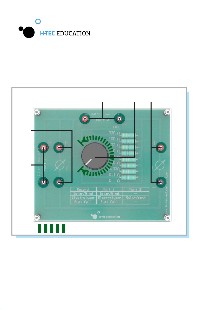
Setting up the Decade Resistor for ExperimentsSetting up the Decade Resistor for Experiments
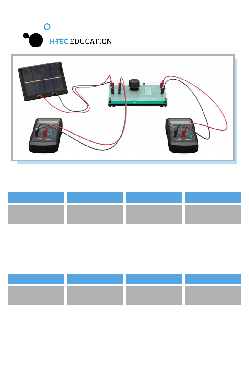
1.) Setting up for experiments with solar modules or wind turbines:1.) Setting up for experiments with solar modules or wind turbines:
The components are connected as follows:
Ensure the correct polarity (red = “+”, black = “-”)!
Ten different resistance values can be set using the rotary switch. Every rotary switch position
produces another operating point.
Risk of damage to the equipment by applying any type of voltage!Risk of damage to the equipment by applying any type of voltage!
Applying any type of voltage to the “U” and “I” connections, may damage set-up
components beyond repair. Never apply any voltage to the “U” or “I” connections!
Risk of damage to the equipment due to electrical overload!Risk of damage to the equipment due to electrical overload!
Connecting components with too high an output voltage or power to the “Port 1” or
“Port 2” connections may damage the decade resistor beyond repair. Never connect
components to the “Port 1” or “Port 2” connections if their electrical output values
exceed the maximum permissible input values at the connections.
Risk of damage to the equipment through improper handling!Risk of damage to the equipment through improper handling!
Using force to turn the rotary switch beyond the permissible switching range will
damage the rotary switch beyond repair. Never use force to activate the rotary switch
and only activate it within the permissible switching range.
CAUTION
CAUTION
CAUTION
Port 1Port 1 Port 2Port 2 UUII
Solar module or wind
turbine
Multimeter
Voltage measurement
Multimeter
Current measurement
-Empty-

8www.myhtec.com
Fig. 2: Set-up example with Solar Module
2.) Setting up for experiments with electrolyzers:2.) Setting up for experiments with electrolyzers:
The components are connected as follows:
3.) Setting up for experiments with fuel cells:3.) Setting up for experiments with fuel cells:
The components are connected as follows:
Ensure the correct polarity (red = “+”, black = “-”)!
Ten different resistance values can be set using the rotary switch. Every rotary switch position
produces another operating point.
Ensure the correct polarity (red = “+”, black = “-”)!
Ten different resistance values can be set using the rotary switch. Every rotary switch position
produces another operating point.
Port 1Port 1
Port 1Port 1
Port 2Port 2
Port 2Port 2
UU
UU
II
II
Solar module or wind
turbine
Multimeter
Voltage measurement
Multimeter
Voltage measurement
Multimeter
Current measurement
Multimeter
Current measurement
Electrolyzer
Fuel Cell - Empty-

www.myhtec.com 9
Please refer to the relevant operating instructions for the technical data of the multimeters
and the stopwatch.
Decade resistor:Decade resistor:
Technical Data
H x W x D:
Connections:
Umax Port 1 & Port 2:
Pmax Port 1 & Port 2:
50 x 160 x 132 mm
female connectors for 2 mm multilam plugs
3.0 VDC
1.20 W

10 www.myhtec.com
Troubleshooting
The measured values are not working.
The measured values are determined to be too low.
Should the above-mentioned solutions not remedy the cause of error, please contactShould the above-mentioned solutions not remedy the cause of error, please contact
H-TEC Education.H-TEC Education.
The components to be measured are not working properly.
Higher currents can magnify contact resistance.
The components are not connected properly.
The decade resistor is damaged.
Make sure the components to be measured are working properly. For
instructions on troubleshooting with regard to the individual components to be
measure, see the relevant operating instructions.
Check all connections for secure, tight connection. However, the values
measured are accurate in a qualitative sense.
Make sure that all the components are connected as described in the “Use of
the Measurement Set” chapter.
Contact H-TEC Education
Possible Cause:
Possible Cause:
Possible Cause:
Possible Cause:
Solution:
Solution:
Solution:
Solution:

www.myhtec.com 11
Before putting the product into storage, the following point must be observed:
The product’s components do not need maintenance. The following points should, however,
be observed:
According to European regulations, used electric and electronic devices may no longer
be disposed of as unsorted household waste. The symbol of the crossed-out wheelie bin
indicates the necessity of separate collection. Your local waste management company can
provide you with additional information about disposal options.
With regard to transport and storage of the product, the following point should be observed
to ensure a long service life. Transport and store only:
Shutting Down
Maintenance
Disposal
Transport and Storage
Remove all batteries from devices.
Only use dry, lint-free cloths to clean the products.
In the original package
Ensure that the batteries in the multimeters and stopwatch are replaced before
they are completely deleted.
Dry and dust-free
At temperatures of 40° - 120° F (4° - 50° C)
Protected from vibrations

© H-Tec Education, 2019. No part of this guide may be reproduced in whole or in part in any
manner without the express written permission of H-Tec Education. Subject to technical changes.
H-TEC EDUCATION
1902 Pinon Dr. Unit B
College Station, TX 77845
USA
Phone: +1 979-703-1925
Fax: +1 979-314-1122
Email: [email protected]
Website: www.myhtec.com
Table of contents
Other H-TEC Education Educational Equipment manuals
Popular Educational Equipment manuals by other brands

Enabling Devices
Enabling Devices Cheap Talk 4 Square Direct user guide

Sony
Sony Vision Exchange PEQ-C100 System Integration & Services Guide

Nasco
Nasco Life form LF01006U instruction manual

LEXIBOOK
LEXIBOOK EDU100i1 instruction manual

SPINNAKER
SPINNAKER STORY MACHINE manual

Pronounce
Pronounce PRO01 user guide