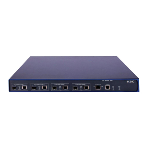
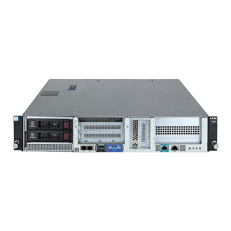
H3C WX5002 User manual

2
Copyright © 2009-2010, Hangzhou H3C Technologies Co., Ltd. and its licensors
No part of this manual may be reproduced or transmitted in any form or by any means
without the prior written consent of Hangzhou H3C Technologies Co., Ltd.
The information in this document is subject to change without notice. Every effort has
been made in the preparation of this document to ensure accuracy of the contents.
However, the statements, information, and recommendations in this document do not
constitute a warranty of any kind, express or implied. Hangzhou H3C Technologies Co.,
Ltd. and its licensors shall not be liable for technical or editorial errors or omissions
contained herein.
Acknowledgments
H3C, , Aolynk, , H3Care, , TOP G, , IRF, NetPilot, Neocean,
NeoVTL, SecPro, SecPoint, SecEngine, SecPath, Comware, Secware, Storware, NQA,
VVG, V2G, VnG, PSPT, XGbus, N-Bus, TiGem, InnoVision and HUASAN are trademarks of
Hangzhou H3C Technologies Co., Ltd.
All other trademarks that may be mentioned in this guide are the property of their
respective owners.
Environmental protection
This product has been designed to comply with the environmental protection
requirements. The storage, use, and disposal of this product must meet the applicable
national laws and regulations.

3
Table of Contents
1Product overview··············································································································· 6
Physical Properties························································································································6
Front panel······························································································································6
Rear panel ······························································································································7
2Installation preparations······································································································ 9
Unpacking and inspection ·········································································································· 10
Installation site examination ········································································································ 10
Installation tools·························································································································· 10
3Installation························································································································11
Installing the access controller onto a 19-Inch rack ······································································· 11
Installing the access controller with front and rear mounting brackets ······································· 11
Installing the access controller with front mounting brackets and a tray····································· 16
Installing the access controller with mounting brackets and slide rails ········································ 18
Installing the access controller on a workbench ··········································································· 20
Connecting the ground wire ······································································································· 20
When a grounding strip is unavailable ····················································································· 22
Connecting the power cord ······································································································· 23
Connecting the AC power cord ····························································································· 23
Connecting the DC power cord ····························································································· 24
Connecting interface cables ······································································································ 25
Connecting the console cable······························································································· 25
Connecting the Ethernet cable to an Ethernet electrical interface············································ 26
Connecting the Ethernet cable to an Ethernet optical interface ··············································· 26
Checking the installation ············································································································ 28
4Initial startup ·····················································································································29
Setting up the configuration environment ···················································································· 29
Connecting a configuration terminal to the access controller··················································· 29

4
Powering on the access controller······························································································· 31
Check before power-on ········································································································ 31
Power-on the access controller······························································································· 31
Software maintenance··············································································································· 33
5Support and other resources ······························································································34
Related documentation ············································································································· 34
Contacting H3C························································································································· 34
Obtaining documentation ····································································································· 34
Technical support ·················································································································· 35
Documentation feedback ····································································································· 35
Document conventions and symbols ··························································································· 35
Conventions·························································································································· 35
Symbols ································································································································ 36
AInstallation of lightning arrester for network interfaces ···························································37
Tools·········································································································································· 37
Installation procedure················································································································· 37
Precautions································································································································ 38
BInstallation of lightning arrester for AC power ·······································································40
CTechnical specifications·····································································································42
Processor and storage ················································································································ 42
Dimensions and weight··············································································································· 42
Fixed interfaces and slots ············································································································ 42
Power input ······························································································································· 43
Components······························································································································ 43
LEDs······································································································································ 43
Fixed interfaces·························································································································· 45
Console port ························································································································· 45
Ethernet interfaces················································································································· 45
Fans······································································································································ 49
Interface numbering··················································································································· 50

5
Requirements on temperature and humidity ················································································ 50
Requirements on cleanness ········································································································ 50
Anti-static requirements ·············································································································· 51
Generation and damage of static electricity··········································································· 51
Protection measures ·············································································································· 51
Wearing ESD-preventive wrist strap·························································································· 52
Electromagnetic environment requirements················································································· 53
Laser safety································································································································ 53
Index ···························································································································54

6
1Product overview
The H3C WX5002V2 access controller is a new-generation wireless access controller
product developed by Hangzhou H3C Technologies Co., Ltd. The WX5002V2 provides
two groups of combo ports. The WX5002V2 also provides an expansion slot for an
additional card. This provides not only strong processing capability but also flexible
system configuration schemes.
In terms of reliability, the WX5002V2 uses pluggable power supply units (PSU). Thus, you
can choose to use double PSUs for high reliability or use a single PSU to be economical.
Physical Properties
Front panel
The WX5002V2 provides two 10/100/1000 Base-T Ethernet electrical interfaces, two 1000
Base-X Ethernet optical interfaces (combo ports) and one console port on its front panel
(see Figure 1

7
Figure 1 Front panel of the WX5002V2
(1) Gigabit Ethernet interface 2—SFP optical interface
(2) 1000 Mbps LED of gigabit Ethernet interface 2
(3) 10/100 Mbps LED of gigabit Ethernet interface 2
(4) 10/100/1000 Base-T auto-sensing Ethernet electrical interface 2
(5) Gigabit Ethernet interface 1—SFP optical interface
(6) 1000 Mbps LED of gigabit Ethernet interface 1
(7) 10/100 Mbps LED of gigabit Ethernet interface 1
(8) 10/100/1000 Base-T auto-sensing Ethernet electrical interface 1
(9) Console port
(10) System LED
(11) LED of the expansion card
(12) LED of power supply 1
(12) LED of power supply 2
Rear panel
The WX5002V2 provides two power supply module slots and one expansion card slot
(see Figure 2
Figure 2 Rear panel of the WX5002V2
(1) PSU 1 (AC/DC)
(2) Handle of PSU 1
(3) OPEN BOOK sign
(4) Power cord retainer for PSU 1
(5) AC power socket of PSU 1
(6) PSU 2 (AC/DC)
(7) Handle of PSU 2
(8) OPEN BOOK sign
(9) Power cord retainer for PSU 2
(10) AC power socket of PSU 2
(11) Expansion card slot
(12) OPEN BOOK sign
(13) Grounding screw
(1) (2)
(3) (7)
(4) (5) (6) (8) (9) (10)
(11)
(12)
(13)
(1) (2) (4) (5) (6) (7) (9) (10) (11) (13)
(12)
(3) (8)

8
OPEN BOOK and CAUTION signs: Refer to related sections when performing the following
operations:
Table 1 OPEN BOOK sign description
Operation
Related section
Connect the power cord
Connecting the AC power cord
Ground the device
Connecting the ground wire
For technical specifications of the WX5002V2, see Appendix C

9
2Installation preparations
WARNING!
Installation and removal of the unit and its accessories must be carried out by qualified personnel.
Read all of the Safety Instructions supplied with your device before installation and operation.
WARNUNG!
Installation und Ausbau der Anlage und ihrer Zubehörteile müssen von qualifiziertem Personal
realisiert werden. Sie müssen vor der Installation oder Bedienung allen beiliegenden
Sicherheitshinweise lesen.
警告
负责安装和日常维护本设备的人员必须具备安全操作基本技能。在操作本设备前,请务必认真阅读和执行
产品手册规定的安全规范。
To avoid device impairment and bodily injury caused by improper use, observe these
rules:
Pull the power plug(s) out of the access controller before cleaning it. Do not clean
the access controller using wet cloth or liquid.
Keep the access controller away from water or dampness. Prevent water or
moisture from entering the chassis of the access controller.
Do not place the access controller on an unstable case or desk. The access
controller might be damaged severely in case of a fall.
Ensure proper ventilation of the equipment room and keep the ventilation vents of
the access controller free of obstruction.
Make sure that the operating voltage is the same one labeled on the access
controller.
Do not open the chassis when the access controller is operating or when electrical
hazards are present to avoid electrical shocks.
When replacing interface modules, wear the ESD-preventive wrist strap to avoid
damaging the interface modules.

10
Unpacking and inspection
Before unpacking the package, ensure that the package is not damaged and that it
does not show signs of water damage. While opening the package and removing the
contents, avoid using excessive force.
The accessories vary with the models. For the exact contents of the package, refer to
the packing list. If the contents do not match the packing list, contact your H3C
representative.
If the package is found to be rusted or water soaked, stop unpacking and contact your
H3C representative immediately.
Installation site examination
The WX5002V2 must be used indoors. You can mount the WX5002V2 in a cabinet or on a
workbench. Ensure that:
Adequate clearance is reserved at the air inlet/exhaust vents for heat dissipation.
The cabinet or workbench is in the environment that has a good ventilation system.
The cabinet is sturdy enough to support the access controller and its accessories.
The cabinet or workbench is well earthed.
To ensure normal operation and long service life of your access controller, install it in an
environment that meets the requirements described in Requirements on temperature
and humidity, Requirements on cleanness, Anti-static requirements, and
Electromagnetic environment requirements in Appendix C
Installation tools
Flat-blade screwdriver
Phillips screwdriver: P2-150mm
ESD-preventive wrist strap
NOTE:
Installation tools and ESD-preventive wrist strap are user-supplied.

11
3Installation
CAUTION:
If you are going to have an H3C agent maintain your access controller, ensure that the
dismantlement-preventive seal on a mounting screw of the access controller chassis is intact. If
you want to open the chassis, you should contact H3C for permission. Otherwise, you are
responsible for consequences resulting from your actions.
This section provides procedures for installing the WX5002V2:
Installing the access controller onto a 19-Inch rack
Installing the access controller on a workbench
Installing the access controller onto a 19-Inch rack
The access controller can be installed onto a 19-inch standard rack in one of the
following ways:
Installing the access controller with front and rear mounting brackets
Installing the access controller with front mounting brackets and a tray
Installing the access controller with mounting brackets and slide rails
Installing the access controller with front and rear mounting brackets
Mounting bracket structure
Figure 3 Front mounting bracket
(1) Screw hole for fixing the front mounting bracket to the rack (use M6 screws)
(2) Screw hole for fixing the front mounting bracket to the access controller
(1)
(2)

12
Figure 4 Rear mounting bracket
(1) Screw hole for fixing the rear mounting bracket to the rack (use M6 screws)
(2) Heat dissipation hole
Installation procedure
1. Put on the EAD-preventive wrist strap and check that the rack is sturdy and properly
grounded.
2. Attach the front mounting brackets to the access controller with screws (which are
packaged with the front mounting brackets) (see Figure 5
Figure 5 Install front mounting brackets to both sides of the access controller
3. Attach a bearing screw (which is packaged with rear mounting brackets) into the
proper installation hole on the rear, upper right and left sides of the access
controller, respectively (see Figure 6
Figure 6 Install bearing screws into the access controller
(1) Three installation holes for bearing screws (choose one as needed)
(2) Bearing screw
(1)
(2)
(1) (2)

13
NOTE:
There are three screw holes on both the right and left sides of the rear, and upper part of the
access controller for installing the bearing screws. Locate the proper hole to install a bearing
screw to each side. The rear mounting brackets can support the weight of the access controller.
4. Determine the position for installing the access controller on the rack. Use screws
and the corresponding cage nuts to fix the rear mounting brackets to the rear
square-hole rack rails (see Figure 7
Figure 7 Install rear mounting brackets to the rack
(1) Rear square-hole rack rails
5. Support the bottom of your access controller with one hand and holding the front
part of the access controller with the other hand, gently push the access controller
into the rack (see Figure 8
(1)

14
Figure 8 Installation with front and rear mounting brackets
(1) Front mounting bracket
(2) Front square-hole rack rail
(3) Bearing screw
(4) Screw for fixing the rear mounting bracket to the rear square-hole rack rail
(5) Rear mounting bracket
(6) Rear square-hole rack rail
6. After the access controller is pushed in, make sure that the upper side of the rear
mounting brackets and the bearing screws are closely touched (see Figure 9
(1)
(2)
(3)
(4)
(5)
(6)

15
Figure 9 Installation with front and rear mounting brackets
(1) Rear square-hole rack rail
(2) Bearing screw
(3) Rear mounting bracket
7. Use screws and the corresponding cage nuts to fix the front mounting brackets to
the front square-hole rack rails, so that the front and rear mounting brackets fix the
access controller on the rack horizontally (see Figure 10
(1)
(2)
(3)

16
Figure 10 Installation with front and rear mounting brackets
(1) Front square-hole rack rail
(2) Front mounting bracket
Installing the access controller with front mounting brackets and a
tray
NOTE:
The tray is an optional component and must be separately ordered.
1. Put on the EAD-preventive wrist strap and check that the rack is sturdy and properly
grounded.
2. Attach the front mounting brackets to the access controller with the screws that are
packaged with the front mounting brackets (see Figure 5
3. Properly position the tray horizontally on the rack (see Figure 11 (This figure is just for
your reference. The installation may differ on a different rack.)
(1)
(2)

17
Figure 11 Install a tray
4. Place the access controller on the tray horizontally. Gently push the access
controller into the rack along the tray, and then use screws and the corresponding
cage nuts to fix the front mounting brackets to the front square-hole rack rails of the
rack (see Figure 12
Figure 12 Installation with front mounting brackets and a tray

18
Installing the access controller with mounting brackets and slide rails
NOTE:
Slide rails are optional components, which need to be separately ordered if needed. H3C slide
rails are suitable for only the H3C standard racks with a depth of 1000 mm (39.37 in.). If the depth
of your rack is different, substitute other supports for the slide rails.
Slide rail
Figure 13 Appearance of a slide rail
(1) Slotted hole, a screw hole for fixing the slide rail to the rear round-hole rack rail of the rack. You
can adjust the screw position within the screw hole according to the device position.
(2) Heat dissipation hole. It is for heat dissipation between the device and rack.
(3) Slotted hole, a screw hole for fixing the slide rail to the front round-hole rack rail of the rack.
Installation procedure
1. Put on the EAD-preventive wrist strap and check that the rack is sturdy and properly
grounded.
2. Attach one end of the front mounting brackets to the access controller with the
screws that are packaged with the front mounting brackets (see Figure 5
3. Install the slide rails to the round-hole rack rails on both sides of the rack using M5
tapping screws (see Figure 14 (This figure is just for your reference. The installation
may differ on a different rack.)
(1)
(2)
(3)

19
Figure 14 Install slide rails
4. Hold the two sides of the access controller with both hands and gently slide the
access controller into a proper position on the rack (see Figure 15 Make sure that
the bottom of the access controller touches the slide rails.
Figure 15 Installation with front mounting brackets and slide rails
NOTE:
Make sure that device is at least 1 U (44.45 mm, 1.75 in.) away from neighboring devices for heat
dissipation.
5. Use M6 screws and cage nuts to fix the front mounting brackets to the front
square-hole rack rails, so that the front mounting brackets and the slide rails can fix
the access controller on the rack (see Figure 16

20
Figure 16 Installation with front mounting brackets and slide rails
Installing the access controller on a workbench
If the standard 19-inch rack is not available, you can install the access controller on a
clean workbench. When installing the access controller on a workbench:
Make sure that the workbench is flat, sturdy and well grounded.
Keep the environment well ventilated and reserve a clearance of 10 cm (3.9 in.)
around the chassis for heat dissipation.
Do not place heavy objects on the access controller.
Keep at least a vertical distance of 1.5 cm (0.59 in.) between access controllers
when they are placed one above the other.
Connecting the ground wire
Other manuals for WX5002
1
Table of contents
Other H3C Controllers manuals
Popular Controllers manuals by other brands

URC
URC Total Control MRX-5 owner's manual

DKS
DKS 1838 owner's manual

Keysight Technologies
Keysight Technologies M9036A PXIe Upgrade or Restore

Weishaupt
Weishaupt W-FM 25 Installation and operating instruction

Donaldson Torit
Donaldson Torit DCE 2000 Series Installation, operation and maintenance manual

CRE Technology
CRE Technology AMF COMPACT quick start

Extron electronics
Extron electronics MediaLink Controllers with IP Link MLC 104 IP... Specification sheet

Norac
Norac U5 installation manual

JDS Technologies
JDS Technologies HomeRunner RBI user manual

Intersil
Intersil ISL6539 Application note

Penn
Penn MR5 Series Product bulletin

Carel
Carel ir33 smart Read me first