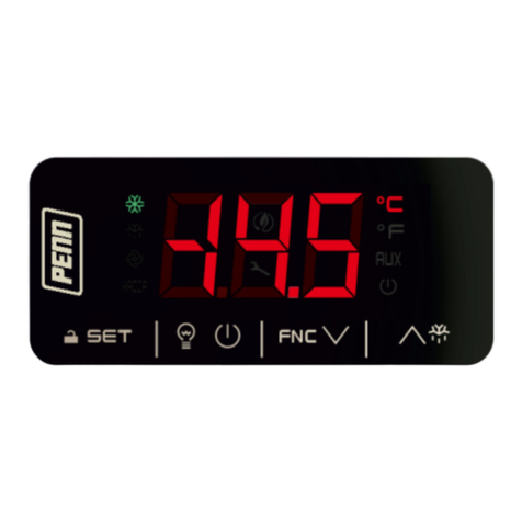
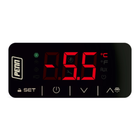
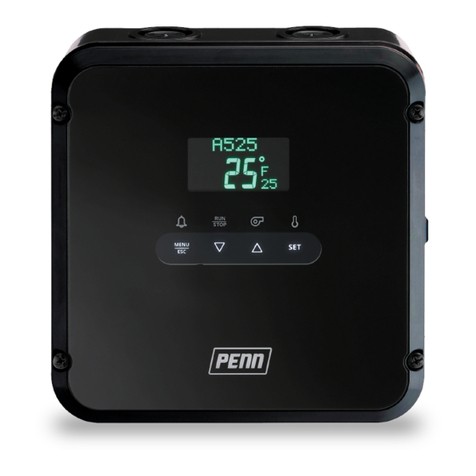
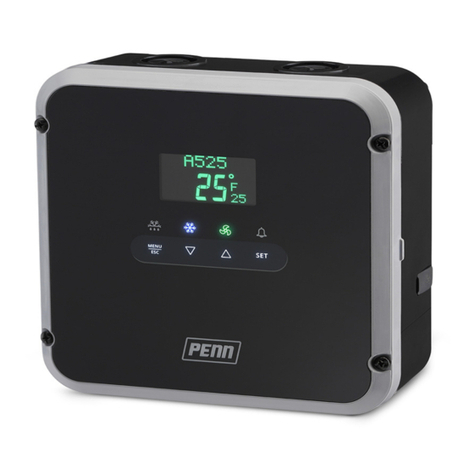
Penn MR5 Series User manual

MR5 Series Panel Mount Case Controller Product
Bulletin
Introduction
The MR5 Series Panel Mount Case Controller controls
compressor, evaporator fan, and defrost cycles to
maintain the temperature of refrigerated units. The MR5
Controller facilitates a defrost cycle and uses time or
temperature to control defrost termination. The MR5
Controller incorporates temperature management, defrost
management, evaporator fan management, and alarm
management control functions.
The MR5 Controllers include models that connect to the
Verasys® Building Automation System (BAS) through
RS485 protocols. You can integrate these models with the
BAS to control and monitor every available MR5 Controller
function.
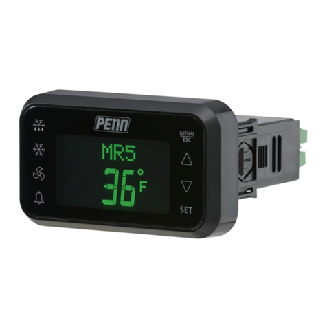
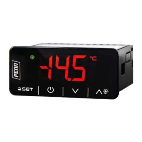
Figure 1: MR5 Controller
Features and benefits
Plain language programming
Displays a scrolling alphanumeric message system
that shows you what to program.
Adaptive or time-based defrost
Provides a choice between a conventional time-
based defrost or the more advanced adaptive
defrost. Adaptive defrost learns and automatically
adjusts the defrost schedule of your system to
improve efficiency.
Meets Title 24 standards
You can program the controller to determine
when to operate the fan or set the fan to off.
This feature provides better air circulation in the
conditioned space and meets energy efficiency
standards.
Alarming
Facilitates program adjustment for high
temperature conditions, low temperature
conditions, door open, refrigerant leaks, high
system pressure, low system pressure, and
sensor failures. Failure messages display in plain,
readable language.
Reporting and recording
Automatically records temperatures at set
intervals to improve food safety. You can also
create reports to show that food was stored at
the required temperatures. You can download the
recorded data to a USB drive, and use the data
for hazard analysis critical control point (HACCP)
purposes.
Program copy and firmware updates
To upload your preferred settings or to update
the controller's operating firmware, the CBL-MR5-
USB accessory plugs into the MR5 comm port and
provides a USB connection. For information about
how to connect the CBL-MR5-USB accessory to the
MR5 Controller refer to the MR5 Series Panel Mount
Case Controller USB Cable Instruction Sheet (Part No.
24-07664-03469).
Applications
You can use the MR5 Controller with reach-in coolers,
merchandisers, and display cases.
Important: Use the MR5 Series Controller only as
an operating control. Where failure or malfunction
of the MR5 Controller could lead to personal injury
or property damage to the controlled equipment
or other property, additional precautions must be
designed into the control system. Incorporate and
maintain other devices, such as supervisory or alarm
systems or safety or limit controls, intended to warn
of or protect against failure or malfunction of the
MR5 Controller.
Important: Utiliser ce MR5 Series Controller
uniquement en tant que dispositif de contrôle
de fonctionnement. Lorsqu'une défaillance
ou un dysfonctionnement du MR5 Controller
Régulateur risque de provoquer des blessures
ou d'endommager l'équipement contrôlé ou un
autre équipement, la conception du système de
contrôle doit intégrer des dispositifs de protection
supplémentaires. Veiller dans ce cas à intégrer de
façon permanente d'autres dispositifs, tels que
des systèmes de supervision ou d'alarme, ou des
dispositifs de sécurité ou de limitation, ayant une
fonction d'avertissement ou de protection en cas
de défaillance ou de dysfonctionnement du MR5
Régulateur.
LIT-12013106
2019-10-08
MR534AFDN, MR534AFDV

Additional Features
User interface
The controller’s system status and setup information
displays on an LCD UI. The status indicator icons show
the defrost, cooling, evaporator fan, and alarm features
and provide a visual indication of the system status and
alarms. The defrost and alarm icons also function as keys
to initiate unscheduled defrost cycles and clear system
alarms. You can use four touchpad keys to navigate
the system, see detailed system information, change
parameter settings, and respond to system alarms.
Refrigeration mode
Refrigeration mode is the normal operating mode of the
MR5 Controller. The system cycles the compressor on and
off, and operates the evaporator fans according to the
setup selections to maintain the setpoint temperature in
the refrigerated space. While in refrigeration mode, the
Fan icon indicates the evaporator fan relay status and
the defrost relay and Defrost icon remain off. The LCD UI
displays the HOME screen, which shows the system name,
date, time, space temperature, and setpoint.
Defrost mode
The selections you make for defrost type, defrost
termination type, and evaporator fan behavior determine
how the refrigeration system operates during defrost
mode. To manually start or stop a defrost cycle, press the
Defrost icon for several seconds.
The MR5 Controller includes the following defrost modes:
• You commonly use off-cycle defrost on medium
temperature refrigeration applications. During off-
cycle defrost, refrigerant flow to the evaporator is
interrupted. The evaporator fans remain on to move air
over the evaporator coil and melt any accumulated frost
or ice.
• Electric defrost uses electric resistive heating elements
that the defrost relay controls to melt the ice, which
accumulates on the evaporator coil during normal
cooling operation. Low-temperature refrigeration
applications often use electric defrost.
• Hot gas defrost systems use a bypass valve controlled
by the defrost relay and extra refrigerant piping to
temporarily reroute the hot gas discharge from the
compressor through the evaporator coil. Low and very
low temperature refrigeration applications use hot gas
defrost.
Defrost termination types
The MR5 Controller can terminate defrost durations
based on time or temperature. Temperature termination
applications use a temperature sensor (SN2) that you
install on the evaporator.
• Time-based defrost terminates the defrost cycle when
the user-defined maximum defrost duration elapses.
• Temperature-sensor defrost terminates the defrost
cycle when the temperature sensed at the evaporator
sensor (SN2) reaches the user-defined defrost
termination temperature.
• Temperature-switch based defrost terminates the
defrost cycle when the temperature at the defrost
termination switch on the evaporator reaches the
switch’s cutout temperature.
Note: The maximum defrost duration overrides both
temperature-sensor and temperature-switch defrost
termination and terminates the defrost cycle, even
if the evaporator does not reach the termination
temperature.
Defrost schedule types
You can set up the following defrost schedule types on the
MR5 Controller:
• Scheduled defrost facilitates the set up of zero defrost
cycles to eight defrost cycles per day on a fixed
schedule. Automatic scheduled defrost sets up the
defrost intervals at equal time frequencies based on
the selected number of defrost cycles per day. Manual
scheduled defrost facilitates the selection of specific
times at which each defrost cycle starts during the day.
• Adaptive defrost does not follow a user-defined time
schedule, but instead continuously adapts to the
refrigeration system conditions and schedules defrost
cycles as needed. Adaptive defrost adjusts the defrost
schedule to achieve a user-defined defrost duration.
You set up the expected defrost duration, the first
defrost interval, and a defrost termination temperature.
The adaptive defrost system adjusts the length of the
defrost interval so that the expected defrost duration
coincides with the time that the evaporator reaches the
termination temperature.
Adaptive defrost setup parameters
The MR5 Controller includes the following adaptive defrost
setup parameters:
• The expected defrost duration is the estimated duration
for a complete defrost of the evaporator coil and how
long it takes for the evaporator to reach the defrost
termination temperature after a typical defrost interval.
During the set up of the adaptive defrost, select from
0 minutes to 99 minutes for the expected defrost
duration.
• The defrost interval is the interval in hours between
the start of consecutive defrost cycles. You can define
the initial defrost interval when you set up the adaptive
defrost feature, and the adaptive defrost feature
shortens or lengthens the defrost interval to adapt to
the required interval. Select from 1 hour to 48 hours for
the initial defrost interval.
• Maximum time between defrosts defines the maximum
hours for any adaptive defrost interval. If the system
calculates a defrost interval greater than the maximum
time that you set, the MR5 Controller ignores the
calculation and starts the next defrost duration based
on the maximum time. Select from 3 hours to 24 hours
for the maximum time between defrosts.
MR5 Series Panel Mount Case Controller Product Bulletin2
• Minimum Time Between Defrosts defines the minimum
hours for any adaptive defrost interval. If the system
calculates a defrost interval that is less than the
minimum time that you set, the MR5 Controller ignores
the calculation and starts the next defrost duration
based on the minimum time. Select from 3 hours to 24
hours for the minimum time between defrosts.
• Blackout periods prevent the occurrence of defrost
cycles during the defined blackout period. You can
schedule daily blackout periods during regular,
predictable periods of high cooling demand. Select
from 0 minutes to 240 minutes for a blackout period.
Compressor and evaporator fan start
delays
To control the compressor and evaporator fan operation,
the MR5 Controller uses the following time delay features:
• The anti-short cycle delay (ASD) holds the compressor
relay off or open after the relay cycles off. The
compressor relay cannot turn on or close again until
the ASD elapses, which protects the compressor from
short cycling. Select from 0 minutes to 12 minutes for
the ASD.
• The evaporator fan drip-time delay holds the
compressor relay and evaporator fan relays off or open
after the defrost duration terminates, which allows any
remaining moisture on the evaporator to drip off. Select
from 0 minutes to 10 minutes for the evaporator drip-
time fan delay.
• The evaporator fan time delay works with the
evaporator fan temperature delay. The evaporator
fan time delay holds the evaporator fan relays off or
open after the defrost termination, drip-time delay,
and compressor start in cooling mode. The evaporator
coil cools down and freezes any moisture before the
evaporator fans start. This delay reduces the moisture
and warm air that blows into the refrigerated space.
The evaporator fan delay is an adjustable time delay
after a defrost cycle. Select from 0 minutes to 15
minutes for the evaporator fan time delay.
System setup parameters
The System Setup parameters define the system
attributes, hardware features, and hard-wired
components of the refrigeration system. The MR5
Controller includes the following system setup
parameters:
• Time and date
• Defrost type
• Defrost termination type
• Evaporator fan type
• Sensor type
• Units of temperature in Celsius or Fahrenheit
• LCD brightness
• System name
Binary inputs and alarms
The MR5 Controller includes the following binary inputs
and alarms:
• The BI1 and BI2 binary inputs interface monitors
binary and analog signals, and defines conditions
and actions based on those signals. The binary inputs
receive signals from a door switch or a refrigerant leak
detector. When the MR5 Controller receives a signal, the
system performs a specific action, such as sounding an
alarm.
• Cooling shutdown occurs when one of the two binary
input modes receives an external signal. When the
system receives an external signal, the MR5 Controller
turns the compressor and fan off.
• System shutdown takes priority over the normal control
of the compressor, defrost, and fan relays. System
shutdowns occur during an alarm condition, such as a
refrigerant leak.
Communication adapter and network
capability
The communication adapter, part number ADPT-MR5-
RS485, is an isolated RS485 adapter that you can use to
interface with a Building Automation System (BAS). The
communication adapter is included with MR534AFDV
models. It is not included with MR534AFDN models, but
you can purchase it separately to add BAS communication.
Figure 2: ADPT-MR5-RS485 communication adapter
connected to a MR5 Controller
MR5 Series Panel Mount Case Controller Product Bulletin 3

Dimensions
The following figure shows the MR5 Controller
dimensions. Figure 4 shows the panel cut-out dimensions
required to insert the MR5 Controller into the panel.
Figure 3: MR5 Controller dimensions, mm (in.)
Figure 4: MR5 Controller panel opening dimensions,
mm (in.)
Ordering information
The following table contains product codes and
descriptions for the MR5 Controller models.
Table 1: MR5 Series Panel Mount Case Controller
models
Product code
number Description
MR534AFDN-000S MR534 Controller only
MR534AFDV-000S
MR534 Controller including
ADPT- MR5- RS485 for Verasys or standard
BACnet.
All A99 temperature sensors work with the MR5
Controller. The following table contains the A99 product
codes and descriptions for the MR5 accessories.
Table 2: Accessories for the MR5 Controller
Product code
number Description
A99BB-200C
Positive temperature coefficient (PTC) silicon
sensor with polyvinyl chloride (PVC) cable;
cable length: 2 m (6.5 ft); range: -40°C to
100°C (-40°F to 212°F)
A99BB-300C
PTC silicon sensor with PVC cable; cable
length: 3 m (9.8 ft); range: -40°C to 100°C
(-40°F to 212°F)
A99BB-400C
PTC silicon sensor with PVC cable; cable
length: 4 m (13.1 ft); range: -40°C to 100°C
(-40°F to 212°F)
A99BB-500C
PTC silicon sensor with PVC cable; cable
length: 5 m (16.4 ft); range: -40°C to 100°C
(-40°F to 212°F)
A99BB-600C
PTC silicon sensor with PVC cable; cable
length: 6 m (19.7 ft); range: -40°C to 100°C
(-40°F to 212°F)
TS-6340KF00
10K ohms negative temperature coefficient
(NTC) sensor with 1.5 m (4.9 ft) cable;
available in Europe only
ADPT-MR5-RS485
RS485 MR5 network communications
adapter kit. Use to connect an MR5
Controller to a BAS system such as Verasys
or standard BACnet.
CBL-MR5-USB MR5 Controller USB cable: Use to connect a
USB drive to the MR5 Controller.
Repair information
Do not attempt to repair or recalibrate the MR5
Controller. If you have a defective or improperly
functioning controller, contact your nearest authorized
Johnson Controls® or PENN distributor or sales
representative with the MR5 Controller model and
product code number.
MR5 Series Panel Mount Case Controller Product Bulletin4

Electrical ratings
Table 3 to Table 6 show the electrical ratings for single-
pole, single-throw (SPST) and single-pole, double-throw
(SPDT) control relays in the MR5 Controller.
Table 3: SPST compressor relay ratings between
terminal 16 and terminal 18
cULus CE
Applied voltage
at 50/60 Hz
24 VAC 120 VAC 240 VAC 240 VAC
Full load
amperes
n/a 5.8 A n/a n/a
Locked rotor
amperes
n/a 34.8 A n/a n/a
Resistive
amperes
8 A 8 A 8 A 8 A
Inductive
amperes
3 A 3 A 3 A n/a
Pilot duty VA 125 VA at 24 VAC to 240 VAC n/a
Number of
cycles
100K
Table 4: SPDT alarm relay ratings between terminal 12
and terminals 10 and 11
cULus CE
Applied voltage
at 50/60Hz
24 VAC 120 VAC 240 VAC 240 VAC
Resistive
amperes
8 A 8 A 8 A 2 A
Inductive
amperes
3 A 3 A 3 A n/a
Pilot duty VA 72 VA 125 VA 125 VA n/a
Number of
Cycles
6K
Table 5: SPST evaporator fan or auxiliary relay ratings
between terminal 12 and terminal 13
cULus CE
Applied voltage
at 50/60Hz
24 VAC 120 VAC 240 VAC 240 VAC
Full load
amperes
n/a 3 A 2.2 A n/a
Locked rotor
amperes
n/a 18 A 13.2 A n/a
Resistive
amperes
8 A 8 A 8 A 5 A
Inductive
amperes
3 A 3 A 3 A n/a
Pilot duty VA 28 VA 125 VA 125 VA n/a
Number of
cycles
30K
Table 6: SPST defrost relay ratings between terminal 16
and terminal 17
cULus CE
Applied voltage
at 50/60Hz
24 VAC 120 VAC 240 VAC 240 VAC
Resistive
amperes
8 A 8 A 8 A 5 A
Inductive
amperes
3 A 3 A 3 A n/a
Pilot duty VA 28 VA 125 VA 125 VA n/a
Number of
cycles
30K
MR5 Series Panel Mount Case
Controller technical specifications
The following table shows the MR5 Controller technical
specifications. Table 8 shows the UL conformity
declaration information. Table 9 shows the PTC
temperature sensor technical specifications. Table 10
shows the NTC temperature technical specifications.
Table 7: MR534 Series Panel Mount Case Controller
technical specifications
Information Description
Product MR534AFD
Power
consumption
12 VA maximum
Supply power
range
120 VAC to 240 VAC nominal, 50/60 Hz, 10 VA
maximum
Ambient
conditions
Operating: -32°C to 60°C (-25°F to 140°F), 0 to
95% RH non-condensing
Shipping and Storage: -40°C to 85°C (-40°F to
185°F), 0 to 95% RH non-condensing
Temperature
sensing range
-40°C to 50°C (-40°F to 122°F)
Input signal
(SN1, SN2, and
SN3)
1,035 ohms at 25°C (77°F) for A99B PTC
temperature sensors
10,000 ohms at 25°C (77°F) for TS-6340 NTC
temperature sensors
Input signal
(BI1 and BI2)
Dry contact binary input with integrated contact
cleaning circuit
Sensor offset
range
±3ºC or ±5ºF
External USB Use a standard USB flash drive to extract HACCP
data, or to install firmware upgrades.
Dimensions (H
x W x D)
58.4 mm (2.3 in.) x 102.00 mm (4.0 in.) x
111.10 mm (4.37 in.)
Weight ~280 grams (0.6173 lb)
Compliance North America:
United States: cULus Listed; UL60730-1 and
UL60730-2-9, File SDFY.SA516; FCC Compliant to
CFR47, Part 15, Subpart B, Class B limits
Canada: cULus Listed; CAN/CSA-E60730 and
CAN/CSA-E60730-2, File SDFY7.SA516; Industry
Canada (IC) compliant to Canadian ICES-003,
Class B limits
MR5 Series Panel Mount Case Controller Product Bulletin 5

Table 7: MR534 Series Panel Mount Case Controller
technical specifications
Information Description
Europe:
CE Mark – Johnson Controls declares that this
product is in compliance with the essential
requirements and other relevant provisions of
the EMC Directive, Low Voltage Directive, and
RoHS Directive.
Australia and New Zealand:
RCM Mark, Australia/NZ emissions compliant
BACnet International:
BACnet testing laboratories (BTL) listed; BACnet
smart sensor (B-SS)
The performance specifications are nominal and conform to
acceptable industry standards. For application at conditions
beyond these specifications Johnson Controls shall not be
liable for damages resulting from misapplication or misuse of
its products.
Table 8: UL conformity declaration information
Information Description
Purpose of control Sensing control or operating control
Construction of
control
Electronic, independently mounted
control that you mount in or on a remote
panel
Compressor relay: 100,000 cycles
Defrost relay: 30,000 cycles
Evaporator fan or auxiliary relays: 30,000
cycles
Number of cycles
Alarm relay: 6,000 cycles
Method of mounting
control
Flush mount into refrigeration panel
opening: 71 mm (2.8 in.) x 29 mm
(1.14 in.)
Degree of IP
protection
Gasket sealed; IP54 category 2
Disconnection type
Alarm relay: SPDT micro-disconnection
type 1.B
Compressor relay: SPST micro-
interruption type 1.C
Evaporator fan or Auxiliary relay: SPST
micro-disconnection type 1.B
Type action
Defrost relay: SPST micro-disconnection
type 1.B
Heat and fire
resistance category
D
Rated impulse voltage 2500 V
Over voltage category II
Pollution degree 4 front face, 2 back housing
Table 9: A99B type PTC temperature sensors
Information Description11
Ambient sensing
and operating
conditions22
Type A99BA and A99BB: -40°C to 100°C (-40°F
to 212°F); 0 to 100% RH, condensing
Type A99BC: -40°C to 120°C (-40°F to 248°F); 0
to 100% RH, condensing
Reference
resistance
1,035 ohms at 25°C (77°F) and 855 ohms at
0°C (32°F)
Accuracy 330.5°C (0.9°F) between -15°C and 57°C (5°F and
134.6°F)
Sensor
construction
Probe: stainless steel; 50 mm x 6.0 mm 2 in. x
0.2 in;
cable length: A99Bx-200 (2 m); A99Bx-300
(3 m); A99Bx-500 (5 m)
Sensor cable
sheath
Type A99BA: shielded PVC cable
Type A99BB: PVC cable
Type A99BC: high-temperature silicon cable
Wire gauge 22 AWG (0.33 mm2)
Ambient storage
conditions
Type A99BA and A99BB: -40°C to 105°C (-40°F
to 221°F); 0 to 100% RH, condensing
Type A99BC: -40°C to 130°C (-40°F to 266°F); 0
to 100% RH, condensing
Shipping weight 41 g (1.4 oz) for 2 m (6 1/2 ft) sensor
1 Refer to the A99B Series Temperature Sensor Product or
Technical Bulletin (LIT-125186) for detailed information about
the A99B sensors.
2 When you connect any A99B Series temperature sensor
to an MR5 Controller, the range of displayed temperature
values is restricted from -40°C to 50°C (-40°F to 122ºF).
3 Refer to the A99B Series Temperature Sensors Product/
Technical Bulletin (LIT-125186) for accuracy rating outside of
this temperature range.
The TS6340K-F00 NTC temperature sensor is available in
Europe only.
Table 10: TS6340K-F00 NTC temperature sensor
Information Description
Ambient sensing
and operating
conditions
-40°C to 50°C (-40°F to 122°F); 0 to 100% RH,
condensing
Reference
resistance
10,000 ohms at 25°C (77°F)
Sensor
construction
Probe: stainless steel 50 mm x 6 mm (2 in. x
0.2 in.)
Cable length: 1.5 m (4.9 ft)
Sensor cable
sheath
PVC cable
North American emissions compliance
United States
This equipment has been tested and found to comply with
the limits for a Class B digital device, pursuant to Part 15
of the FCC Rules. These limits are designed to provide
reasonable protection against harmful interference in
a residential installation. This equipment generates,
uses and can radiate radio frequency energy and, if not
MR5 Series Panel Mount Case Controller Product Bulletin6

installed and used in accordance with the instructions,
may cause harmful interference to radio communications.
However, there is no guarantee that interference will
not occur in a particular installation. If this equipment
does cause harmful interference to radio or television
reception, which can be determined by turning the
equipment off and on, the user is encouraged to try to
correct the interference by one or more of the following
measures:
• Reorient or relocate the receiving antenna.
• Increase the separation between the equipment and
receiver.
• Connect the equipment into an outlet on a circuit
different from that to which the receiver is connected.
• Consult the dealer or an experienced radio/TV
technician for help.
Canada
This Class (B) digital apparatus meets all the requirements
of the Canadian Interference-Causing Equipment
Regulations.
Cet appareil numérique de la Classe (B) respecte toutes
les exigences du Règlement sur le matériel brouilleur du
Canada.
Product warranty
This product is covered by a limited warranty, details
of which can be found at www.johnsoncontrols.com/
buildingswarranty.
Points of single contact
APAC Europe NA/SA
JOHNSON CONTROLS
C/O CONTROLS PRODUCT
MANAGEMENT
NO. 32 CHANGJIJANG RD NEW
DISTRICT
WUXI JIANGSU PROVINCE 214028
CHINA
JOHNSON CONTROLS
WESTENDHOF 3
45143 ESSEN
GERMANY
JOHNSON CONTROLS
507 E MICHIGAN ST
MILWAUKEE WI 53202
USA
MR5 Series Panel Mount Case Controller Product Bulletin 7

© 2019 Johnson Controls. All rights reserved. All specifications and other information shown were current as of document revision and
are subject to change without notice.
www.penncontrols.com
Other manuals for MR5 Series
1
This manual suits for next models
2
Table of contents
Other Penn Controllers manuals

Penn
Penn MR5 Series Service manual

Penn
Penn A421 Series User manual

Penn
Penn P66AAB-1 User manual

Penn
Penn P47 Series User manual

Penn
Penn TC3203 User manual

Penn
Penn TC3B23 User manual

Penn
Penn TC3223 User manual

Penn
Penn A19ZBA User manual

Penn
Penn A52 Series Service manual

Penn
Penn A421 Series User manual
Popular Controllers manuals by other brands

Hobbico
Hobbico TorqMaster 90 quick start guide

GESTRA
GESTRA NRR 2-52 Original Installation & Operating Manual

Under Control
Under Control MANETTE FILAIRE SWITCH How to connect

Akai
Akai MPD226 user guide

BridgIoT
BridgIoT Geasy MK6 instruction manual

PCB Piezotronics
PCB Piezotronics IMI SENSORS 683A101000 Installation and operating manual