haacon 1889.5 User manual

haacon hilft heben
haacon hebetechnik gmbh
Josef-Haamann-Str. 6
D-97896 Freudenberg/Main
Tel: +49 (0) 93 75/84-0
Fax: +49 (0) 93 75/84-66
e-mail: [email protected]
Internet: www.haacon.de
094204_c_gb_hebvrr_v haacon hebetechnik gmbh – Phone +49 (0) 9375 - 84-0 – Fax +49 (0) 9375 - 8466 1
Operating manual
Lifting device for containers
without connection shafts
Type 1889.5 - 207966

094204_c_gb_hebvrr_v haacon hebetechnik gmbh – Phone +49 (0) 9375 - 84-0 – Fax +49 (0) 9375 - 8466 2
This operating manual is to be kept on the lifting device. It must be ensured that everybody who must complete
work on the lifting device can examine this operating manual at any time. In addition, the
operating manuals described in the Safety of Work Law and the Equipment Usage Directive must be provided.
All safety and operating notice signs on the machine are to be kept in a clearly legible condition at all times. Da-
maged or illegible signs are to be replaced immediately.
Content
1.Safetyinstructions ..............................................................3
2.Technicaldata..................................................................5
3.General .......................................................................6
4.Structure......................................................................6
5.Delivery.......................................................................6
6.Mountingtheliftingdevice........................................................7
7.Operating......................................................................8
8.Servicing......................................................................9
9.Spareparts....................................................................9
10. Dismounting and waste disposal ..................................................9

094204_c_gb_hebvrr_v haacon hebetechnik gmbh – Phone +49 (0) 9375 - 84-0 – Fax +49 (0) 9375 - 8466 3
1. Safety instructions
Duty of care of the operator
The lifting device Type 1889 has been designed and
built to after the careful selection of the
harmonised standards with which it must comply and
other technical specifications. It is therefore state of
the art and offers maximum safety.
However, this safety level can only be achieved in
practice if all the action required for it is actually taken.
It is a matter for the operator of the lifting device to
plan this action and to check that it is implemented.
The operating must in particular ensure that
the lifting device is only used for the purpose for
which it is design (see the section entitled General).
the lifting device is only operated if it is in perfect
working order and special safety equipment is
checked regularly to ensure that it remains fully
functional.
the operating manual is available at the place of use
of the lifting device at all times in legible
condition.
only suitably qualified and authorised personnel is
allowed to operating, service and repair the lifting
device.
this personnel is instructed at regular intervals in
all matters of industrial safety and environmental
protection and that they are familiar with the opera-
ting manual and the safety instructions contained
there in.
all the safety and warning notices on the lifting
device remain on the device and are kept in legible
condition.
nobody is on, in or under the container with the
mounted lifting device during the lifting or lowering
procedure.
persons only enter the system if the distance bet-
ween the bottom of the container and the ground is
less than 400 mm or load holders are fitted to act as
additional safety devices pursuant to VBG 14.
Basic safety action
To prevent damage and fatal injuries when operating
the lifting device, do not
exceed the maximum (see section entitled Techni-
cal data).
allow people to ride on the device.
work in, on or under the raised load if it exceeds
the maximum height off the ground or load holders
pursuant to VBG 14 are fitted.
–
–
–
–
–
–
–
–
–
–
–
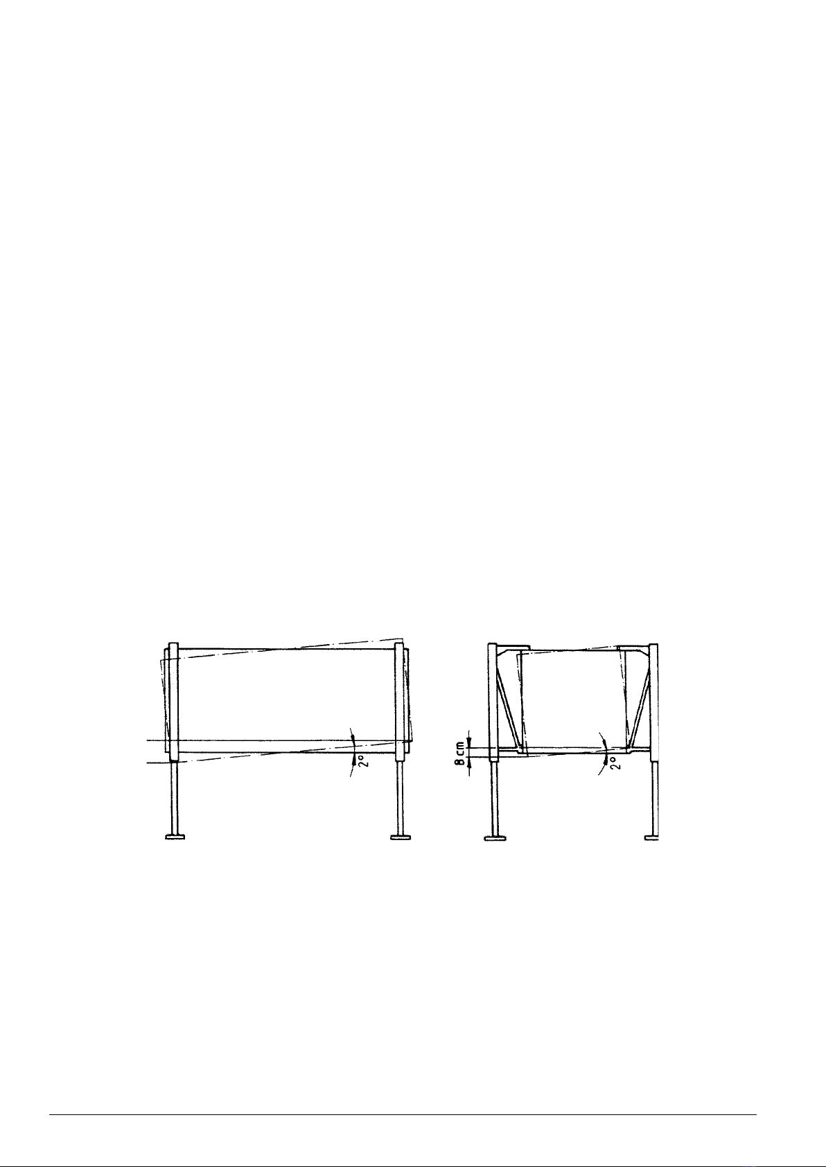
exceed the maximum angle (see section entitled
Other instructions).
set up the device in wind speeds in excess of
64 kph.
You must also ensure that if you wish to lift the maxi-
mum load the centre of gravity of the load is positioned
as centrally as possible between the supports.
Requirements on the operating personnel
The lifting device Type 1889 may only be operated by
people who have been trained, instructed and autho-
rised to do so. These people must be familiar with the
operating manual and act accordingly. The authority of
the operating personnel must be defined clearly.
Damage or defects on the lifting device are to be re-
ported to the appropriate person without delay. Do not
work with the lifting device until the damage or defect
has been rectified.
Servicing and repair work
Servicing and repair work may only be completed by
trained personnel.
Do not make any unauthorised modifications to the
lifting device for safety reasons – this particularly
applies to welding work on load-bearing parts. All
planned modifications must be approved in writing by
haacon hebetechnik gmbh.
Only use original spare parts / original wear parts.
These parts have been specially designed for the
machine. If you use other parts it cannot be guaran-
teed that they are designed and built to withstand the
stresses safely. Parts and special equipment that are
not supplied by haacon hebetechnik gmbh have not
been approved for use on the lifting device.
The maintenance work set out in the operating manual
(cleaning, lubrication, servicing, inspection, etc.) must
be completed on schedule.
–
–

094204_c_gb_hebvrr_v haacon hebetechnik gmbh – Phone +49 (0) 9375 - 84-0 – Fax +49 (0) 9375 - 8466 4
Side view
Max. incline with a cab width,
for example, of 2.2 m = 8 cm
Length view
Max. incline with a cab length,
for example, of 4.25 m = 15 cm
Figure 1-1
Other instructions
Important!
Exercise great care when driving the carrier vehicle
below the container. The lorry must not strike the
container since otherwise there is a risk that the
lifting device will bend.
Have somebody guide the lorry!
People must not be allow to stand in, on or under
the container during the lifting and lowering proce-
dure.
People may stand on and in the raised container
if it is no more than 400 mm off the ground or load
holders pursuant to VBG 14 are fitted.
The lifting device with a container must not be
made to vibrate by means of crank impulses.
The container may only be placed on solid ground
by the lifting device.
The area on which the container is placed or from
which it is lifted must be as flat as possible.
1.
2.
3.
4.
5.
6.
The maximum angle of 2° applies to all types with a
maximum load and at full lifting height.
If the site incline is greater than 2°,
all four supports must be loaded uniformly.
the cab must be aligned horizontally.
To eliminate the bending stress on the gear rack tu-
bes, the stress must be removed form the supports
individually.
the sag of the gear rack tubes must be
observed. It must be even.
additional safety devices may be required if larger
angles are used or the gear rack tubes are exposed
to considerable sag.
the centre of gravity of the container must be central.
9. Do not set up the device in storms.
7.
8.
–
–
–
–
–

094204_c_gb_hebvrr_v haacon hebetechnik gmbh – Phone +49 (0) 9375 - 84-0 – Fax +49 (0) 9375 - 8466 5
Technical instructions on the lifting device
To prevent accidents and damage, notice signs (figure 1-2) are affixed to the landing gear (figure 1-3) , and the
instructions there on must be followed:
Figure 1-2
Figure 1-3
All the safety signs and operating instruction signs on the lifting device are to be kept clearly legible at all times.
Damaged or illegible signs are to be replaced without delay.
2. Technical data
TYPE 1889.5
Maximum load / set t 5
Maximum load / support t 2,5
Weight / set approx. kg 260
Installation time / 2 men min. 10
Lifting time min. 10
Crank force / Support pair N 150
Lift / turn of crank mm 5,8
Lift mm 1750
Design height *) mm 2330
*) Minimum design height with a lift of 1750 mm.

094204_c_gb_hebvrr_v haacon hebetechnik gmbh – Phone +49 (0) 9375 - 84-0 – Fax +49 (0) 9375 - 8466 6
3. General
The lifting device Type 1889 is designed to move and position containers with a maximum gross weight of 5
tonnes. It consists of four rack supports with spur gears and fold-out suspension unit. The support plates, top
arm and the cranks are removable. During transport the lifting device Type 1889 is removed and stowed in the
appropriate storage boxes or the supplied stowing device (optional).
The lifting device Type 1889 has a self-inhibiting spur gear, which holds the load securely at any height (you must
nevertheless comply with the safety instructions).
The rack supports form a stable unit with the container. The large support plates means that the device can be
used anywhere in the open air where there is firm ground.
The rack supports are connected using two telescoping connection shafts (apart from the version with an auto-
matic levelling system) and driven in pairs using the two cranks supplied.
4. Structure
The lifting device has a robust tubular steel construction.
The gear rack support is a product that has proven its worth over many decades that offers a long service life and
operational reliability. The gear has an internal load lock that holds the load at any height.
The rack supports with the fold-out suspension unit, top arm and support plates form a corner unit. One ratchet
crank per pair of supports completes the lifting device.
An electric drive can be retrofitted to the lifting device Type 1889.
The gear rack support complies with VBG 8 and the EC Machine Directive 98/37/EEC and subsequent directives.
When the load holders (additional safety devices on the rack) are used with the device at a standstill the support
complies with VBG 14.
5. Delivery
1 lifting device set Type 1889 consists of:
4 rack supports with fold-out suspension unit
4 top arms
4 support plates
2 Ratchet cranks
1 open-ended spanner, 30 mm
Accessories (optional)
Electric drive
Winch
Stowing device
Load holder VBG 14
–
–
–
–
–
–
–
–
–

094204_c_gb_hebvrr_v haacon hebetechnik gmbh – Phone +49 (0) 9375 - 84-0 – Fax +49 (0) 9375 - 8466 7
6. Mounting the lifting device
1. Take the crank out of its storage positi-
on and fit it on the gear.
2. Fit the top arm. 3. Align the supports individually, place
them on the ground and unfold the
suspension unit.
4. Support ready for mounting. 5. Raise the support until the top arm
projects over the cabin.
6. Crank downwards until the journal
engages in the top corner fitting and
the arm sits on the cabin.
7. Insert the locking bolt on the bottom
support arm in the corner fitting, turn
it through 90° and engage the locking
lever in the mounting.
8. Turn the nut on to the locking bolt by
hand and then tighten it with a 30 mm
ring spanner.
9. Lifting device ready for use (excluding
connection shaft).
10. Container raised 500 mm (excluding
connection shaft).
11. Raised 1600 mm. Ready for the truck
to be driven under it (excluding con-
nection shaft).
Dismantle following the above procedure in reverse.

094204_c_gb_hebvrr_v haacon hebetechnik gmbh – Phone +49 (0) 9375 - 84-0 – Fax +49 (0) 9375 - 8466 8
Positioning plan
Rear
Plan view
Mark the bottom ISO corner
fittings, supports and stowing
device with numbers 1 and 2.
Front of vehicle
Door side
⇑
direction of moving
The positioning plan shows the numbering of supports 1 and 2 depending on the position of the ISO corner fit-
tings on the container. The individual supports must be fitted in the order of these numbers.
7. Operating
To avoid danger for persons and the machine, before you lift a container it is essential to ensure the following
The container has been released from the carrier vehicle.
The rack supports have been mounted in their correct operating position.
The lifting capacity has not been exceeded.
Adequately compacted ground is available.
To raise the container, first make sure that the gear rack supports are in contact with the ground using the ratchet
cranks. Then align the container by adjusting each support separately. The supports can now be extended indivi-
dually with the ratchet cranks fitted and the container raised to the required level.
–
–
–
–

094204_c_gb_hebvrr_v haacon hebetechnik gmbh – Phone +49 (0) 9375 - 84-0 – Fax +49 (0) 9375 - 8466 9
8. Servicing
The lifting device Type 1889 is to be inspected by an expert at intervals that depend on the conditions in which it
is used, but at least once per year (annual safety inspection pursuant to Accident Prevention Directive
BGV 8, §23, Sub-Section 2). In addition to the annual inspection all the safety parts must be tested every ten
years (including all gear parts such as the safety lock, etc.). We recommend that you have this safety check con-
ducted by haacon hebetechnik gmbh.
Experts are persons who, as a result of their training and experience, have adequate knowledge in the field of
winches, lifting and towing equipment and are familiar with the relevant state industrial safety directives, regula-
tions and generally acknowledged rules of engineering (for example DIN EN standards) so that they can assess
the safe condition of winches, lifting and towing equipment.
Servicing work
Description Intervals Parts / Numbers
Grease gear Depending on usage, at
least every month Grease nipple
Clean and grease gear rack Every month Steel brush,
spray on Gleitmo
Grease all the moving parts of the
suspension construction Every quarter 55, 56, 57, 59, 69, 75
Shell Alvania R3
9. Spare parts
Only use original spare parts / original wear parts. These parts have been specially designed for the machine.
If you use other parts it cannot be guaranteed that they are designed and built to withstand the stresses safely.
Parts and special equipment that have not been supplied by us have not been approved by us for use on the
lifting device.
Please quote the following to order spare parts:
Type: – See model plate
Factory No: – See model plate
Part No: – See spare parts list / drawing
Description: – See spare parts list / drawing
Spare parts list / drawing
See attachments
10. Dismounting and waste disposal
Safety instructions have to be observed.
The disposal of the product and its components has to be according to environmental standards.
–
–

094204_c_gb_hebvrr_v haacon hebetechnik gmbh – Phone +49 (0) 9375 - 84-0 – Fax +49 (0) 9375 - 8466 10
1. Open the gear
1.1 Remove the screws (38 - 41) and take off the casing plate (28).
1.2 Remove the gear wheel (8), centre drive (14) and gear wheel (13).
1.3 Remove the complete crank drive (29 - 34). Ensure that the locking pawls (32) are installed again in the same
position.
1.4 Remove the complete safety lock (19).
1.5 To remove the rack drive (7), pull out the rack to the end of the stroke since there is only a bevel on the top
tooth on the rack, which allows the rack to be installed and removed.
2. Remove the rack (4)
2.1 Before pulling out the rack, remove the gear parts as described in 1.2 to 1.5.
3. Remove the arm and rack (53 - 67)
3.1 Drive out the clamp sleeve (68).
3.2 Remove the bolt (67).
3.3 Drive out the clamp sleeve (63).
3.4 Release the threaded hub (64).
3.5 The parts can now be removed.
4. Remove the locking bolt (36, 55 - 57)
4.1 Drive out the clamp sleeve (36).
4.2 Remove the handle (57).
4.3 Unscrew the nut (56).
4.4 The parts can now be removed.
Assemble the parts following the above instructions in reverse.

094204_c_gb_hebvrr_v haacon hebetechnik gmbh – Phone +49 (0) 9375 - 84-0 – Fax +49 (0) 9375 - 8466 11

094204_c_gb_hebvrr_v haacon hebetechnik gmbh – Phone +49 (0) 9375 - 84-0 – Fax +49 (0) 9375 - 8466 12

094204_c_gb_hebvrr_v haacon hebetechnik gmbh – Phone +49 (0) 9375 - 84-0 – Fax +49 (0) 9375 - 8466 13

094204_c_gb_hebvrr_v haacon hebetechnik gmbh – Phone +49 (0) 9375 - 84-0 – Fax +49 (0) 9375 - 8466 14

094204_c_gb_hebvrr_v haacon hebetechnik gmbh – Phone +49 (0) 9375 - 84-0 – Fax +49 (0) 9375 - 8466 15

094204_c_gb_hebvrr_v haacon hebetechnik gmbh – Phone +49 (0) 9375 - 84-0 – Fax +49 (0) 9375 - 8466 16

094204_c_gb_hebvrr_v haacon hebetechnik gmbh – Phone +49 (0) 9375 - 84-0 – Fax +49 (0) 9375 - 8466 17
This manual suits for next models
1
Table of contents
Other haacon Lifting System manuals