2-1
5 - DASH / AUTO
SECTION 2 – SAFETY AND PRECAUTIONS
INTENDED USE
Most accidents occur as the result of
failure to follow basic and fundamental safety
rules and precautions. Recognizing potential
safety hazards, following correct and safe
operating procedures described in this
manual, and complying with safety warnings
located throughout the machine and
attachment may reduce the risk of accidents.
There is no way to completely eliminate
the potential for danger when operating
agricultural equipment. Therefore, you must
study this operator’s manual and understand
how to operate the attachment controls for
safe operation before using the attachment.
Likewise, never let anyone operate the
attachment without proper instruction.
Do not operate the attachment for
anything other than its intended use. Hagie
Manufacturing Company shall not be liable
for any damage, injury, or death associated
with improper use of the attachment.
Do not make any modifications such as,
but not limited to, weldments, add-ons,
adaptations, or changes from the original
design of the attachment. Such modifications
may become safety hazards to you and
others and will void all warranties.
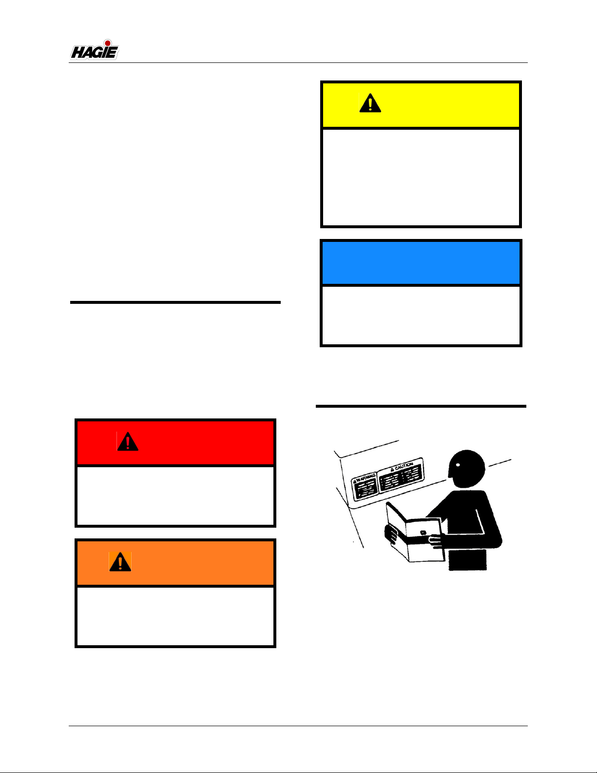
Replace missing, faded, or damaged
safety signs. Refer to “Safety Decals”
elsewhere in this section for correct sign and
placement.
SAFETY PRECAUTIONS
General Safety
• Before operating the attachment, ensure
there are no obstacles or persons in the
path of travel.
• Keep clear of all moving parts and keep
others away while operating.
• The hydraulic and electrical control sys-
tems are optimized for use with this
attachment. Any modification to these
systems may lead to unintended or
uncontrolled motion. Do NOT install add-
on control systems that are not approved
by Hagie Manufacturing Company.
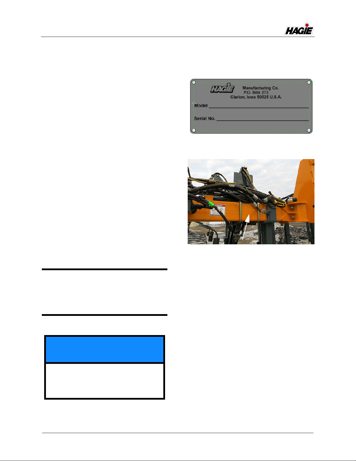
• Some conditions cannot be completely
safeguarded against without interfering
with efficient operation of the machine
and/or reasonable accessibility. In these
cases, decals have been installed to pro-
vide the operator with hazard informa-
tion. Do NOT remove decals for any
reason. If a decal is damaged or miss-
ing, contact your local John Deere
dealer for replacement.
Wear Protective Clothing
• Do not wear loose fitting clothing that
could get caught in moving parts. Wear
safety equipment that is appropriate for
the job.
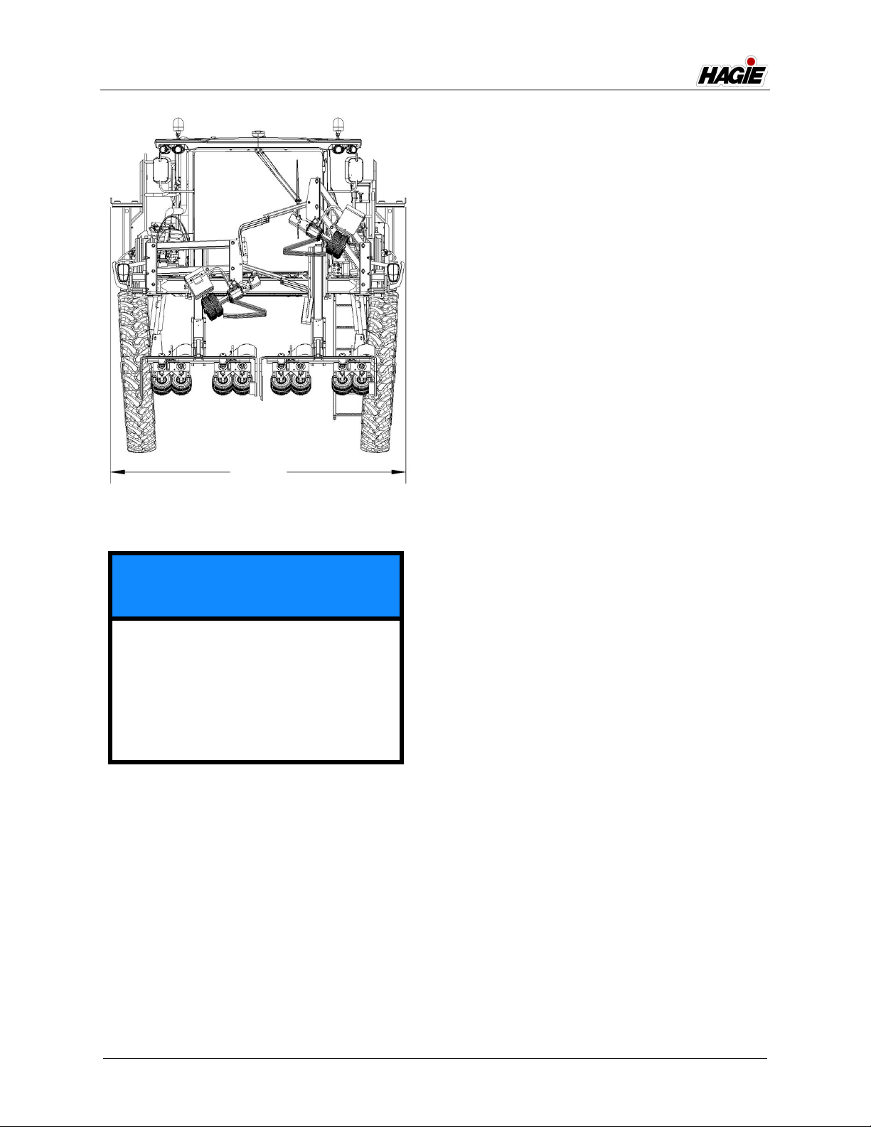
NOTICE
This attachment is designed for and
intended to be used for the removal of
tassels from the tops of corn plants. Use
in any other way or for any other purpose
is considered misuse of this attachment.