WARNING
CAUTION
WARNING
CAUTION
This system should be applied to places of office, restaurant, residence and the like. Appliaction to inferior
environment such as engineering shop could cause equipment malfunction.
Please entrust installation to either the company which sold you the equipment or to a professional contractor.
Defects from improper installations can be the cause of water leakage, electric shocks and fires.
Execute the installation accurately, based on following the installation manual. Again, improper installations can
result in water leakage, electric shocks and fires.
When a large air-conditioning system is installed to a small room, it is necessary to have a prior planned
countermeasure for the rare case of a refrigerant leakage, to prevent the exceeding of threshold concentration.
In regards to preparing this countermeasure, consult with the company from which you purchased the equipment,
and make the installation accordingly. In the rare event that a refrigerant leakage and exceeding of threshold
concentration does occur,there is the danger of a resultant oxygen deficiency accident.
For installation, confirm that the installation site can sufficiently support heavy weight. When strength is insufficient,
injury can result from a falling of the unit.
Execute the prescribed installation construction to prepare for earthquakes and the strong winds of typhoons and
hurricanes, etc. Improper installations can result in accidents due to a violent falling over of the unit.
For electrical work, please see that a licensed electrician executes the work while following the safety standards
related to electrical equipment, and local regulations as well as the installation instructions, and that only exclusive
use circuits are used.
Insufficient power source circuit capacity and defective installment execution can be the cause of electric shocks and
fires.
Accurately connect wiring using the proper cable, and insure that the external force of the cable is not conducted to
the terminal connection part, through properly securing it. Improper connection or securing can result in heat
generation or fire.
Take care that wiring does not rise upward, and accurately install the lid/service panel. Its improper installation can
also result in heat generation or fire.
WARNING
In either case, important safety related information is indicated, so by all means, properly observe all that is mentioned.
After completing the installation, along with confirming that no abnormalities were seen from the operation tests, please
explain operating methods as well as maintenance methods to the user (customer) of this equipment, based on the owner's
manual.
Moreover, ask the customer to keep this sheet together with the owner's manual.
Please read these "Safety Precautions" first then accurately execute the installation work.
Though the precautionary points indicated herein are divided under two headings, and
those points which are related to the strong possibility of an installation done in error
resulting in death or serious injury are listed in the section. However, there is also a
possibility of serious consequences in relationship to the points listed in the section as well.
- 7 -
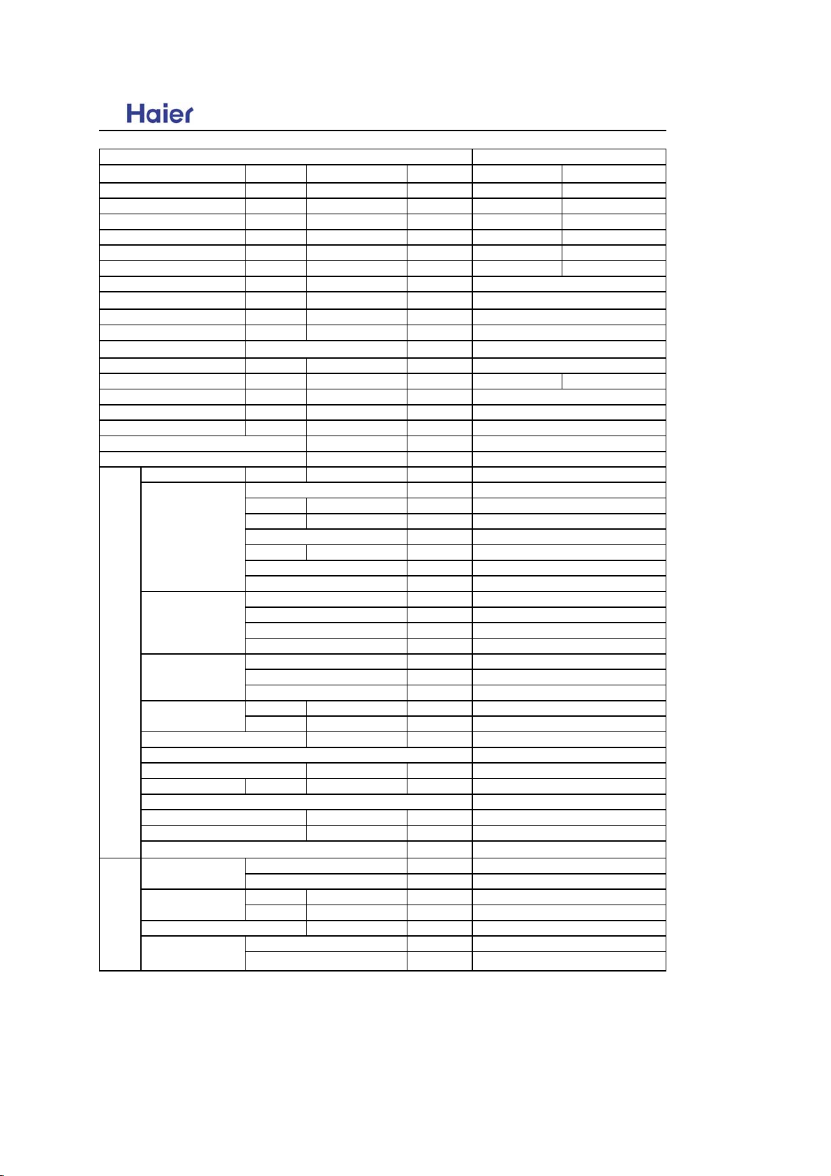
3 SAFETY PRECAUTIONS
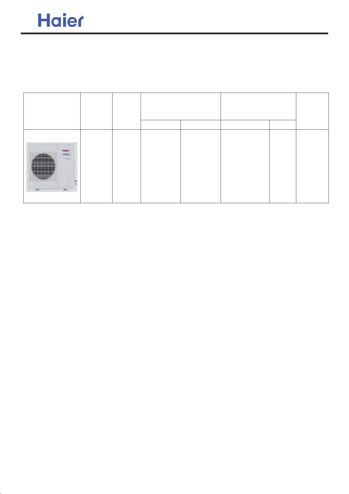
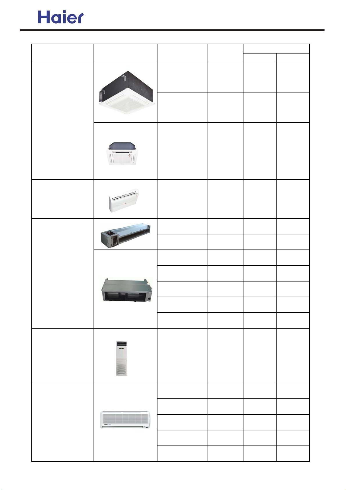
Commercial Air Conditioner Model: A282FHAHA
 User manual")


 null")