HAKO 474 User manual

®
Table of Contents (English)
1. Packing List......................................................... 1
2.Specications ...................................................... 1
3.Precautions ......................................................... 2
4.PartNames (DesolderingGun/Station)............ 3
5.Operation (Preparation-
AssemblyandConnection).... 4•5
(Desoldering)........................... 5•6
(CleaningduringOperation) ......... 7
(ProblemsduringDesoldering). 7•8
(Post-operationMaintenance) ...... 8
(TroubleshootingGuide)............... 8
6.Maintenance (DesolderingGun) ................. 9•10
(Station).......................................11
7.ReplacementParts
(ReplacingHeatingElement)...... 12
8.PartsList (Station)............................... 13•14
(DesolderingGun) ...................... 15
9.ReplacementParts............................................ 15
10.Wiring ................................................................ 16
l
Thank you for purchasing the HAKKO 474 Desolder-
ing Tool.
Please read this manual before operating the HAKKO
474.
Keep this manual readily accessible for reference.
l
CAUTION
Removethepumpsecuringscrew(M4×25
markedred)fromthebottomofthestation.
Failuretodosomayresultinseriousprob-
lems.
吸錫槍
Instruction Manual
使用說明書
日本白光牌
目錄(中文)
1.包裝清單......................................................................... 17
2.規格.................................................................................. 17
3.安全及使用上的注意事項............................................ 18
4.部件名稱(吸錫槍/控制臺)..................................... 19
(準備 --- 裝配和連接).......................20.21
(吸錫)..................................................21.22
(使用時 , 進行清理工作).........................23
(
除錫時發生故障
)....................................... 23
(使用後的保養)......................................... 24
(排除故障指南)......................................... 24
6.保養 (吸錫槍)..............................................25.26
(控制臺)...................................................... 27
7.更換部件......................................................................... 28
8.部件清單(控制臺)..............................................29.30
(吸錫槍)...................................................... 31
10.電路圖............................................................................. 16
●
承蒙惠顧 , 謹致謝忱。
使用 HAKKO474 之前 ,請詳閱本使用說明書 , 正
確使用。
閱後請妥為收存 ,以備日後查閱。
●
注意
使用之前必須除去機身底下的泵拴緊螺絲
(M4×25紅色記號 ), 否則可能導致嚴重後
果。
English 中 文

1
1. Packing List
Station ............................................................. 1
DesolderingGun.............................................. 1
IronHolderBase.............................................. 1
SpringIronHolder ........................................... 1
CleaningSponge............................................. 1
FilterPipe ........................................................ 1
CeramicPaperFilter(S).................................. 2
CeramicPaperFilter(L) .................................. 4
SpringFilter ..................................................... 3
CleaningPin(forø1.0mm[0.04in]nozzle)
............ 1
CleaningPin(forHeatingElement)................. 1
CleaningPinHolder......................................... 1
CleaningDrill(forø1.0mm[0.04in]nozzle)
........... 1
SiliconeGrease ............................................... 1
Wrench ............................................................ 1
InstructionManual ........................................... 1
Please check to make sure that all the items listed below are included in the
HAKKO474package.
Station Wrench IronHolderBase SpringIronHolder
SpringFilterFilterPipe CeramicPaperFilter(L)
CleaningPinHolder
CleaningPin
forø1.0mm(0.04in)Nozzle
CleaningPinforHeatingElement
DesolderingGun
CleaningDrill
forø1.0mm(0.04in)Nozzle
SiliconeGrease
CleaningSponge
CeramicPaperFilter(S)
2. Specications
Name
Powerconsumption
HAKKO474
100W
Part Name
Output
Vacuumgenerator
Vacuumpressure(max.)
Suctionow
Tiptogroundpotential
Tiptogroundresistance
Outerdimension
Weight
24V ~
Vacuumpump,doublecylindertype
80kpa(600mmHg)(24in.Hg)
15 l/min.
<2mV(typical0.6mV)
< 2Ω
165(W)×135(H)×260(D)mm
(6.5×5.31 ×10.24in.)
3.8kg(8.4lb.)
Part Name
PartNo.
Powerconsumption
Temperature range
Insulationresistance
Nozzleinsidediameter
Outerdimensions
Weight,lesscord
HAKKO809
C1183
24V–50W
380to480°C(716to896°F)
>300MΩat420°C(790°F)
ø1.0mm(0.04in.)(nozzleSstandard)
135(W)×174(H)mm(5.31×6.85in.)
200g(0.44lb.)
lDesoldering Gun
Conditionofmeasurement
• Insulationresistance
Theinsulationresistancewasmeasuredbetweenthenozzleandtheleadoftheheatingelementusinga500VDCinsulationresistancemeter.
Caution:Theinsulationresistancecannotbemeasuredbetweenthenozzleandthepowerplugasthetransformerbetweenthesecondarypart
(heatingelement)andtheprimarypartactsasaninsulator.
• Voltageleakage
Thevoltageleakagewasmeasuredbetweenthenozzleandthegroundingplugatatemperatureof480°C(896°F)usinganACmVmeter.
Caution:Besuretogroundtheunitbeforemeasuringthevoltageleakage.
• Specicationsanddesignaresubjecttochangewithoutnotice.
lStation
English
NOTE:
* Thisproductisprotectedagainstelectrostaticdischarge.
* Specicationsanddesignaresubjecttochangewithoutnotice.

3. Precautions
2
Inthisinstructionmanual,“WARNING”and“CAUTIONS”aredenedasfollows.
WARNING
WARNING: Misusemaypotentiallycausedeathof,orseriousinjurytotheuser.
CAUTION : Misusemaypotentiallycauseinjurytotheuserorphysicaldamage
totheobjectsinvolved.
Foryourownsafety,besuretocomplywiththeseprecautions.
CAUTION
Removethepumpsecuringscrew(M4×25markedred)from
thebottomofthestation.
Failuretodosomayresultinseriousproblems.
Whenthepowerison,thenozzletemperatureisbetween
380°C/716°Fand480°C/896°F.
Sincemishandlingmayleadtoburnsorre,besuretocomplywith
thefollowingprecautions.
lDonottouchthemetallicpartsnearthenozzle,nearbyplasticpartsandthe
springironholder.
lDonotusetheproductnearammableitems.
lAdviseotherpeopleintheworkareathattheunitcanreachaveryhightem-
peratureandshouldbeconsideredpotentiallydangerous.
lTurnthepoweroffwhiletakingbreaksandwhennishedusingtheunit.
lBeforereplacingpartsorstoringtheunit,turnthepoweroffandallowtheunit
tocooltoroomtemperature.
Topreventdamagetotheunitandensureasafeworkingenviron-
ment,besuretocomplywiththefollowingprecautions.
lDonotusetheunitforapplicationsotherthandesoldering.
lDonotrapthedesolderinggunagainsttheworkbenchtoshakeoffresidual
solder,orotherwisesubjecttheirontosevereshocks.
lDonotmodifytheunit.
lUseonlygenuineHAKKOreplacementparts.
lDonotwettheunitorusetheunitwhenyourhandsarewet.
lSettheceramicpaperlter(S)forthelterretainer(station),andtheceramic
paperlter(L)forthelterpipe(gun).
lMaintainthedesolderinggunandthestation.
lWhileusingtheunit,don’tdoanythingwhichmaycausebodilyharmorphysi-
caldamage.
English
CAUTION:
Thisproductincludessuchfeaturesaselectricallyconductiveplasticpartsandgroundingof
thehandpieceandstationasmeasurestoprotectthedevicetobesolderedfromtheeffects
ofstaticelectricity.Besuretoobservethefollowinginstructions:
1. Thehandleandotherplasticpartsarenotinsulators,theyareconductors.When
replacingpartsorrepairing,takesufcientcarenottoexposeliveelectricalpartsor
damageinsulationmaterials.
2. Besuretogroundtheunitduringuse.

4. Part Names
3
lDesoldering Gun
lStation
(Refertop.19,20&21forpartnos.)
Nozzle
Transmitsheatformeltingsolder,En-
tranceformeltedsolder.
Expendablepart.
Heating Element
Insiderequirescleaning.
Trigger
Squeezetostartabsorption.
Donotpullthetriggerbefore
fullyheatingthenozzle.
Filter Pipe
Settheceramicpaperlter(L)(No.A1033).
Containsmeltedsolderanduxusinglters.
Filtersareexpendableparts.Back Holder As-
sembly
Securesthelter
pipe.
Release Knob
Pushdowntoremove
thelterpipe.
Indicator
Indicateswhennozzle
andheatingelement
needcleaningand
whenltersneed
replacing.
(refertop.9)
Hose
Connectstothevacuumoutlet
cap(station).
Cord Assembly
Connectstothereceptacle(station).
Temperature Control Knob
Providesnozzletemperaturecon-
trol.(refertop.7)
Temperature Control Set Screw Clamp
Preventsthetemperaturecontrolknobfrombe-
ingreset.(refertop.7)
Vacuum Outlet Cap
Settheceramicpaperlter(S)(No.
A1009).
Connectswiththehose.Filterinside
vacuumoutletcapisexpendable.
Receptacle
Connectorforthecord
assembly.
Power Lamp
Lightsupwhenthepowerswitch
isturnedtoON.
Power Switch
WhenturnedtoON,theheating
elementstartstoheatup.
CAL (Calibration)
Usedforcalibratingthetemperature
afterreplacingtheheatingelement.
Power Cord
Fuse Holder
•100,110Vunit
contain125V-2Afuse.
•120Vunitcontains
250V-2A(U)fuse.
•220,230Vunitcontain
250V-1Afuse.
•Australian240Vunit
contains250V-1A S
fuse.
English

4
5. Operation
SpringIronHolder
(No.B1094)
CleaningPinHolder
(No.B1095)
Tube(red)
CleaningSponge
Securelyinsertthe
cleaningpinholder.
IronHolderBase
Preparation-Assembly and Connection
AssembletheHAKKO474onaatsurface.
1. Remove the pump securing
screw (M4 ×25 marked red)
from the bottom of the station.
2. Assemble the iron holder.
• Setthespringironholderand
cleaningpinholderintheiron
holderbase.
• Dampenthecleaningspongewith
waterandthensqueezeitdry.
CAUTION
Thespongeiscompressed.
Itwillswellwhenmoistenedwithwater.
Besuretodampenthespongewith
waterbeforeuse.
Besuretoremovetheroundportionof
thesponge.
3. Insert the desoldering gun
and cleaning pins.
• Fullyinsertthedesolderingguninto
thespringironholder.
CAUTION
Thespringironholderbecomes
extremelyhotduringoperationofthe
desolderinggun.Donottouchthe
springironholderduringandimmedi-
atelyafterusingthegun.
4. Connections
CAUTION
Besuretoturnoffthepowerswitch
beforeconnectingordisconnecting
thecordassemblyandthepowerplug.
FailuretodosomaydamagetheP.W.B.
• Connectthecordassemblytothe
receptacle(marked“IRON”).
• Connectthehosetothevacuum
outletcap(marked“VACUUM”).
Insertthecordas-
semblybykeyingthe
plugtothekeyon
thereceptacle. Securetheplugby
turningitclockwise.
Fullyinsertthehose
intothevacuumout-
letcap.
English

5
Thepowerlampdoesn’tlight
up.
1. Isthepowercordproperlycon-
nected?
2. Isthefuseblown?
Thenozzledoesn’theatup.
1. Isthecordassemblyproperly
connected?
2. Istheheatingelementbroken?
Thepowerlamp
lightsup.
Thenozzleheatsup.
CAUTION :Thedesolderinggunmustbeplacedintheiron
holderwhennotinuse.
5. Power switch
• Conrmthatthepowerswitchisset
intheOFFposition,thenconnect
thepowerplugtothepowersource.
CAUTION
Theentireunitisconstructedofcon-
ductivematerials.Alwaysgroundthe
unit.
• TurnthepowerswitchtoON.
Thepowerlampshouldlightup.
• Thenozzlebeginstoheatupas
soonasthepowerswitchisturned
toON.
6. After turning the power
switch to ON, wait 3 min-
utes before beginning de-
soldering operations.
5. Operation
Desoldering
AfterturningthepowerswitchtoON,
wait3minutesbeforebeginningdesol-
deringoperations.
1. Set the temperature.
CAUTION
Alwayssetthetemperaturetoaslow
aspossiblefortheworkbeingdone.
• Tomorepreciselysetthetempera-
ture,measurethetemperatureat
thenozzleusingasolderingiron
thermometerandadjustthetem-
peraturecontrolknobaccordingly.
WerecommendtheHAKKO191
thermometerorHAKKO192soldering
testerformeasuringthenozzletem-
perature.
• Thetemperaturecontrolknobcan
besecuredbytighteningthetem-
peraturecontrolsetscrewclamp
(“+”screw)atthetopoftheHAKKO
474 unit.
Lock
Unlock
Securethetemperature
controlsetscrewclampwith
acrosspointscrewdriver.
Thetemperaturecanbeadjustedbetween380°C(716°F)and480°C(896
°F)withtemperaturecontrolknob.
Pleaserefertothechartbelow,andadjustthetemperaturecontrolknob.
knob
1and2
3and4
5and6
P.W.B.
Single-sidedP.W.B.
Through-holeP.W.B.
MultilayerP.W.B.
CAUTION
Neverinsertthecleaningpininthe
holeoftemp.controlsetscrewclamp.
Asthismayresultindamagetothe
unit.
English

6
Wipeawayanyoxideoroldsolder
fromthenozzleusingtheholein
thecenterofthesponge.
2. Clean the tip of the nozzle.
• Keepthesolder-platedsectionof
thenozzleashinywhitebycoating
itwithasmallamountofsolder.
Ifthetipofthenozzleiscoatedwith
oxide,thenozzle’sheatconductivity
willbelowered.
Coatingthetipwithasmallamount
offreshsolderensuremaximumheat
conductivity.
3. Melt the solder.
• Applythenozzletothesoldered
partandmeltthesolder.
CAUTION
Neverallowthenozzletotouchthe
boarditself.
• Conrmthatthesolderismelted.
CAUTION
Toconrmthatallsolderismelted,
observetheinsideoftheholeandthe
backsideoftheP.W.B.Ifthisisdifcult
todo,tryslowlymovingtheleadwith
thenozzle–Iftheleadmoves,the
solderismelted.
CAUTION
Nevermovetheleadbyforce.Ifit
doesn’tmoveeasily,thesolderisn’tyet
fullymelted.
4. Absorb the solder.
• Afterconrmingthatthesolderis
completelymelted,absorbthesol-
derbysqueezingthetriggeronthe
gun.
CAUTION
Neverleaveanysolderremaining
insidetheholeintheP.W.B.
• Afterfullyabsorbingallthesolder,
coolthesolderingjunctioninorder
topreventitfrombecomingresol-
dered.
5. Problems during desolder-
ing.
• Ifsolderremains,resolderthecom-
ponentandrepeatthedesoldering
process.
Nozzle
P.W.B.
Solder
Lead
Slowlymove
theleadwith
thenozzle.
Absorbthesolderbyslowly
movingtheleadbackand
forthwiththetipofthe
nozzle.
English

7
5. Operation
Heatedsolderanduxcancauseoxidestoformandadheretothenozzleandthe
insideoftheheatingelement.Theseoxidesnotonlylowertheheatconductivity,but
canalsoclogthenozzleandheatingelement,resultinginadropinsuctionefciency.
Shouldtherebeanoticeabledropinsuctionefciencyduringoperation,replacethe
lterandcleanthenozzleandheatingelementwiththeprovidedcleaningpin.
Cleaning during Operation
1. Observing the indicator
Whilelookingattheindicatorand
withtheholeofthenozzleopen,
pullthetriggerandlookatthein-
dicator.Ifitisred,cleanthenozzle
andheatingelement,emptythe
lterpipe,andreplacethelters.If
theindicatorisblue,cleaningisnot
necessaryandoperationscanbe
resumed.
CAUTION
Theindicatorwillnotoperateaccuratelyif
theholeofthenozzleisclosedorifthesol-
derintheholeoftheP.W.B.isnotmelted.
CAUTION
TheindicatorontheHAKKO475reads
inadifferentway.
Forinstructiononthereadingthe
HAKKO475indicator,pleasereferto
theHAKKO475instructionmanual.
2. Replacing the lter
Replacethelterasshown1to3.
Duringoperation,thelterpipeis
veryhot.Waituntilthelterpipeis
coolbeforereplacingthelter.
Werecommendkeepingasecond
lterpipecontainingnewltershan-
dy,andreplacingtheinstalledlter
pipewiththisbackuplterpipe.
3 Replacetheentirelterpipe
withheprovidedbackuplterpipe. 2 Pull
1 Down
Normal
Blueorslight
amountofred
can be seen.
Abnormal
Morethanhalf
oftheindicator
isred.
Solution
Iftheindicatorismorethan
halfred,replacethelter
andcleanthenozzleand
theinsideoftheheating
element.
(refertop.12Maintenance
oftheDesolderingGun)
CAUTION :Ifthereisanoticeabledropinsuction
efciency,cleanthenozzleandheatingele-
mentwiththecleaningpin.
Problems during Desoldering
A. The solder in the junction is
not sufciently melted.
B. Suction power is dropping.
A. The solder in the junction is not sufciently melted.
lTemperature is not high enough
Thefollowingpartsrequireagreaterheatcapacitytodesolder.
• MultilayerP.W.B.s,powersupplies,groundplanesinthrough-hole
P.W.B.s,high-capacitytransistors,triacswithheatradiationns,tuner
P.W.B.groundwires,andlarge-scaletransformerterminals.
UseapreheatingovenorheatingguntoheattheP.W.B.toatemperaturethat
won’tdamagetheboardoritscomponents[between70°C(160°F)and80°C(180
°F)],thendesolder.Donotincreasethetemperatureofthegunbyrecalibration
asthismaydamagetheP.W.B.anditscomponents.
lNozzle is worn out.
• Whenthenozzlebeginstowearout,theheatingefciencybegins
todecline.Checkthenozzle.Ifthesolderplatingisdamaged,orthe
nozzleiseroded,replacethenozzle.(refertop.9)
English

8
Post-operation Maintenance
Toensurealongservicelife,alwaysper-
formthefollowingmaintenanceprocedures
immediatelyafterusingtheHAKKO474
unit.
B. Suction power is dropping.
• Replacethelters,andcleanthenozzleandtheinsideoftheheating
element,(refertop.12top.16,MaintenanceofDesolderingGunand
Station)
lAir is leaking from the vacuum system.
Airleakagecannotbedeterminedfromtheindicator.
Checktheair-tightnessofthefollowingpartsandreplaceanythatare
worn.
n Removeallsolderfromtheinsideofthenozzleandheatingelement.
n Cleanthetipofthenozzlewiththecleaningsponge,thencoatthetip
withafreshlayerofsoldertoprotectthesolderplating.
a.
Contactpointofthenozzle
andheatingelement
b.Frontholderandnearby
parts
c.O-ringinthebackholder
d.Hose
e.Vacuumoutletcap
f. Packingandnearbyparts
Troubleshooting Guide WARNING :Ifthepowercordisdamaged,itmustbereplacedbythe
manufacturer,itsserviceagentorsimilarityqualiedperson
inordertoavoidpersonalinjuryordamagetotheunit.
lPower lamp does not light up.
• Isthepowercordpluggedincorrectly.
Securelyinsertthepowercordintothepowersupply.
• Isthefuseblown?
Determinewhythefuseblewandeliminatethecause,thenreplace
thefuse.
ExampleIstheinsideofthegunshort-circuited?
lPump does not operate.
• Isthecordassemblyproperlyconnected?
Reconnectthecordassembly.(refertop.4)
•
Isthenozzleorholeintheheatingelementclogged?
Cleanit.(refertop.9)
lSolder is not being absorbed.
• Isthespringlterfullofsolder?
Replaceitwithanewone.(refertop.10)
• Istheceramiclterhardened?
Replaceitwithanewone.
• Isthereavacuumleak?
Checktheconnectionsandreplaceanywornparts.(refertop.8)
lThe nozzle does not heat up.
• Isthedesolderingguncordassemblyproperlyconnected?
Reconnectit.(refertop.4)
• Istheheatingelementdamaged?
Replaceit.(refertop.12)
NOTE : Whenrepairsareneeded,pleasesendboththedesolderinggun
andthestationtoyoursalesagent.
English

6. Maintenance
9
Properlymaintained,theHAKKO474desolderinggunshouldprovideyearsofgoodservice.
Efcientdesolderingdependsuponthetemperature,andthequalityandquantityofthesolderandux.Per-
formthefollowingserviceproceduresasdictatedbytheconditionsofthegun’susage.
WARNING :
Sincethedesolderingguncanreachaveryhightemperature,pleaseworkcarefully.
Exceptwhencleaningthenozzleandheatingelement,alwaysturnthepowerswitchoffanddiscon-
nectthepowerplugbeforeperforminganymaintenanceprocedure.
Servicing the Desoldering Gun
CAUTION
Thedesolderinggunwillbeextremelyhot.
Duringmaintenance,pleasewearglovesand
workcarefully.
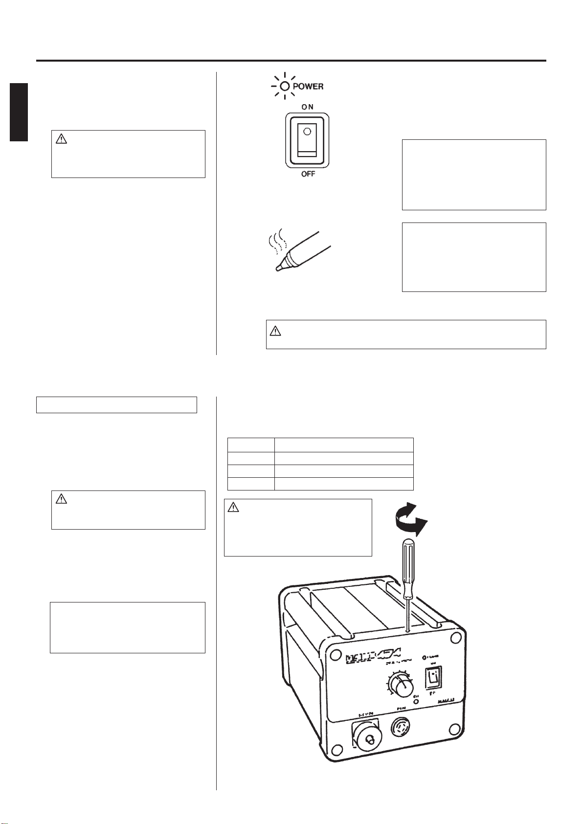
1. Inspect and clean the nozzle.
• Pluginthepowercord,turnthe
powerswitchOnandletthenozzle
heatup.
• Cleanouttheholeofthenozzle
withthenozzlecleaningpin.
CAUTION
Thecleaningpinwillnotpassthroughthe
nozzleuntilthesolderinsidethenozzleis
completelymelted.
• Ifthecleaningpindoesnotpass
throughtheholeinthenozzle,
cleanwiththecleaningdrill.
• Checktheconditionofthesolder
platingonthetipofthenozzle.
• Ifitisslightlyworn,recoatthetipwith
freshsoldertopreventoxidation.
• Checktheconditionofthesurface
andinsideholeofthenozzle.
• Ifeitheriswornoreroded,orthe
insidediameterseemsunusually
wide,replacethenozzle.
CAUTION
Theinsideholeandthesurfaceofthe
nozzleisplatedwithaspecialalloy.
Shouldthisalloybecomeerodedbyhigh-
temperaturesolder,thenozzlewillnotbe
abletomaintainthepropertemperature.
2. Disassemble the heating
element.
CAUTION
Theheatingelementisveryhotduring
operation.
3. Clean out the hole in the
heating element with the
provided cleaning pin.
CAUTION
Besurethesolderintheholeintheheat-
ingelementiscompletelyheated,before
cleaningthehole.
• Ifthecleaningpincannotpass
throughthehole,replacetheheat-
ingelement.
• Turnthepoweroffaftercleaning.
Cleaning with the nozzle cleaning pin
Cleaning with the cleaning drill
•Beforecleaning
•Aftercleaning
Solderplating
Diameterofholeiswid-
enedthrougherosion.
(DesolderingGun)
Thecleaningpinpassescom-
pletelythroughthehole.
Insertthebitwhileturningitclockwise.
Pullthedrillbitoutstraightwithoutturningit.
CAUTION
Ifthecleaningdrillisforcedintothenozzle,
thedrillbitcouldbreakorbedamaged.
CAUTION
Pleaseusethepropersizecleaningpinor
cleaningdrillforthenozzlediameter.
CAUTION
Unfortunately,itisoftendifculttoobserve
thiscondition.Therefore,ifdesoldering
efciencygoesdownandallotherparts
appeartobeOK,thenozzleisprobably
erodedandshouldbereplaced.
HeatingElement ElementCover
Nozzle Nut
Removethenutwiththeattachedwrench.
Scrapeawayalloxidationfromtheholeintheheatingelementuntilthe
cleaningpinpassescleanlythroughthehole.
Thecleaningpinpassescleanly
andcompletelythroughthehole.
English

10
6. Assemble the heating ele-
ment.
• Attachthenozzleandsecurely
tightenthenutwiththeattached
wrench.
CAUTION
Ifthenutisloose,airwillleakandthe
temperaturewilldrop.
CeramicPaper
Filter(L)
(No.A1033)
Attachthefrontholdertothelterpipe
sothatitdoesnotleakair.
Firmlypressthebackholderassembly
intothelterpipeinordertoproperly
seattheO-ringagainstthepipe.
FrontHolder
SpringFilter CeramicPaper
Filter(L)
(No.A1033)
Replace
Stiffandcracked.
Replace
Solderiscollectedintwo-thirdsofthespringlter.
Replace
Ceramicpaperlterisstiffwithuxandsolder.
4. Replace the lters.
• TurnthepowerswitchOFF,
• Whenthelterpipeiscooltothe
touch,pushdownthereleaseknob
atthebackofthegunandremove
thelterpipe.
CAUTION
Thelterpipeisveryhot.
• Examinethefrontholder.
• Examinethespringlter.
• Examinetheceramicpaperlter(L).
(No.A1033)
5. Secure the lters.
• Attachthespringltertothefront
holder
• Attachthefrontholdertothelter
pipe.
CAUTION
Besurethefrontholderiscorrectly
aligned.
CAUTION
Usetheceramicpaperlter(L)forthe
lterpipe(gun).Usingoftheceramic
paperlter(S)inthelterpipemay
causetobreakorthepowertodrop.
English

11
6. Maintenance (Station)
Cleaning the inside of the Filter Case
Cleaning the Pump
WARNING
Unplugthepowercordbeforestartingthis
procedure.
1. Disassemble the pump heads.
• Removetherearpanel.
• Removethecover.
• Removethepumpheadfromeach
sideofthepump.
2. Clean the pump head.
• Removethevalveplateandxing
plate.
• Removeanyuxadheringtothe
plates.
CAUTION
Ifthexingplateisdifculttoremove,
applyhotairtoittowarmitup.
Neveruseexcessiveforcetoremovethe
plateasitiseasytobend,andabent
platewillallowairtoleakoutandreduce
soldervacuumingefciency.
CAUTION
Cleantheplatesonlywithalcoholorthinner.
Replace
Ifthevalveplateisbentorstiff,replaceit.
• Iftheexhaustlterisdirty,replace
it.
3. Assemble the pump heads.
Reassemble the valve plate and
xing plate.
CAUTION
Whenassemblingthepump,besureto
checkforairleaks.
VACUUM
CeramicPaper
Filter(S)
(No.A1009)
FilterRetainer
Removethelterretainer
andpushouttheceramic
paperlter.
Cover RearPanel
Remove
thescrews
Remove
thecoverscrews.
(right/left)
Cleanthepumphead
andxingplate.
FixingPlate
ValvePlate
PumpHead
ExhaustFilter
PumpHead
ValvePlate
Besurethepartsare
alignedcorrectly.
1. Replace the ceramic paper
lter (No.A1009).
Removetheceramicpaperlter
andinspectit.Ifitisstiffwithux,
replaceit.
2. Reassemble the lter case.
CAUTION
Settheceramicpaperlter(S)forthe
lterretainer(station).
Usingtheceramicpaperlter(L)inthe
lterretainermaycausetobreakorthe
powertodrop.
Securethevacuumoutletcap.
ApplysiliconegreasetotheO-ring(S20)andsecurely
tightenthevacuumoutletcaptopreventairleakage.
FixingPlate
English

12
7. Replacement Parts
Replacing the Heating Element
WARNING
Unplugthepowercordbeforestartingthis
procedure.
Theresistancevalueofaworking
heatingelementis2-4Ωat23°C(73°
F).Ifthevalueyougetisoutsidethis
range,replacetheheatingelement.
1. Disassemble the heating
parts.
2. Separate the housing.
3. Detach the terminal and re-
move the heating element.
4. Insert a new heating ele-
ment and reassemble.
(Heatingelement24V-50W)
CAUTION
Beforereassemblingenclosure,make
sureconnectorsarecompletelycov-
eredbytheglasstube.
5. Recalibrate the tempera-
ture.
Theresistanceofnewheatingele-
mentvaries,resultinginvariations
inoperatingtemperatures.Itisnec-
essarytorecalibratethetempera-
tureeverytimetheheatingelement
isreplaced.
• Setthetemperaturecontrolknobto
1andallowtheguntowarmupfor
3 minutes.
• Usingatipthermometer,adjust
thetemperaturecalibrator(marked
“CAL”)untilthenozzletemperature
readsat380°C(716°F).
Housing
Removethelterpipe.
Unscrewthescrews.
Detach
theterminal.
GlassTube
Covertheglasstubeonthe
connectingpart.
Pushin.
Positiontheleadsingrooveand
pressthemintoplace.
Becarefulthattheleadsdonot
getcaughtinthehousing.
Bendthelead
beforeinsertingit.
High
Low
Adjustthetemperaturecalibra-
tor(CAL)withastraight-edge(–)
screwdriver.
English

1
2
3
7
8
38
23
12
13
16
17
18
19
20
15
24
22
21
30
29
28
32
31
33
34
35
36
37
27
39
26
25
14
10
11
9
6
5
4
Specications
100-24V
110-24V
120-24V
220-24,230-24,240-24V
W/ratinglabel
w/ofuse
w/ofuseAustralian240V
125V-2A/100,110V
250V-1A/220,230V
250V-1A S/Australian240V
250V-2A(U)/120V
8. Parts List
Note:Spareorrepairpartsdonotincludemountingscrews,iftheyarenotlistedonthedescription.
13
(Station)
PartNo.
B1029
A1009
B1063
B1031
B1034
B1038
B1036
B1028
B2061
B1093
B1061
B1044
B2057
Part Name
Vacuumoutletcap
Ceramicpaperlter(S)
Filterretainer
Vacuumoutletretainer
O-ring(S20)
Coverforsecuringscrew
Receptacle
Knob
Frontpanel
Cover
Handle
Temp.controlsetscrewclamp
P.W.B.
Specications
10pcs.
W/O-ring(S20)
Setof4
Oneside
Oneside
W/potentiometer
PartNo.
B2063
B2065
B2077
B2078
B2080
B2444
B2067
B1041
B1134
B1042
B1138
B1139
B1275
Part Name
Hoseassembly
Transformer
Transformer
Transformer
Transformer
Pumpassembly
Rearpanel
Fuseholder
Fuseholder
Fuse
Fuse
Fuse
Fuse
PanHeadScrewwith
WasherM3×6
FlatHeadScrew
M4×8(4)
PanHeadScrewwith
WasherM3×6(4)
FlatHeadScrew
M4×12(2)
HexagonSocket
SetScrew
M4×6
PanHeadScrew
M5×10(4)
InternalToothLockWasher
norminalsize4(2)
TrussScrew(Zn,black)
M4×5(2)
PanHeadScrewwith
WasherM4×10(8)
English
ItemNo.
1
2
3
4
5
6
7
8
9
10
11
12
13
ItemNo.
14
15
16
17
18
19

1
2
3
7
8
38
23
12
13
16
17
18
19
20
15
24
22
21
30
29
28
32
31
33
34
35
36
37
27
39
26
25
14
10
11
9
6
5
4
14
ItemNo.
27
28
29
30
31
32
33
34
35
36
37
38
39
PartNo.
B1057
B2060
B2059
B2058
B2085
A1013
B1056
A1014
B1050
B1059
B1313
B1064
B2506
Part Name
Ringforbearing
Crankshaft
Pumpframe
Motor
Diaphragmsettingplate
Diaphragm
Fixingplate
Valveplate
Pumphead
Exhaustlter
Filterretainingpin
Filtercasejoint
Damper
Specications
W/ascrew
Setof2W/screws
Setof2
W/screws
Setof2
Setof2
PanHeadScrew
withWasher
M3×6(2)
PanHeadScrew
withWasher
M4×30
PanHeadScrew
withWasher
M4×8(2)
Spacernominal
size4×25
PanHeadScrew
M4×25
HexagonNut
M4(4)
SpringWasher
nominalsize4(4)
PanHead
Screw
withWasher
M4×8
PanHeadScrew
M5×10(4)
TappingScrew
M2.6×6(4)
TappingScrew
M2.6×6(2)
PanHeadScrew
M3×55
PanHeadScrew
withWasher
M4×8(2)
ExternalTooth
LockWasher
nominalsize4
English
ItemNo.
20
21
22
23
24
25
26
PartNo.
B2068
B2079
B2081
B2082
B2083
B3505
B2066
B1037
B1084
B1078
B1053
B1312
Part Name
Powercord,
3wiredcord&Americanplug
Powercord,3wiredcordbutnoplug
Powercord,
3wiredcord&Australianplug
Powercord,3wiredcord&BSplug
Powercord,
3wiredcord&Europeanplug
Powercord,
3wiredcord&Americanplug
Chassis
Rubberfoot
Switch
Potentiometer
Balanceweight
Crank
Specications
U.S.A.
Setof4
W/bearing

Specications
Forheatingelement
Forø0.8mm(0.03in.)nozzle
Forø1.0mm(0.04in.)nozzle
Forø1.3mm(0.05in.)nozzle
Forø1.6mm(0.06in.)nozzle
Forø0.8mm(0.03in.)nozzle
Forø1.0mm(0.04in.)nozzle
Forø1.3mm(0.05in.)nozzle
Forø1.6mm(0.06in.)nozzle
Specications
1
2
3
7
8
9
5
6
4
13
16
17
15
14
10
11
9
12
15
ItemNo.
1
2
3
4
5
6
7
8
9
10
11
PartNo.
A1314
A1030
A1033
B2073
A1012
B1018
B1019
B1020
B2074
B1023
A1319
Part Name
Frontholder
Springlter
Ceramicpaperlter(L)
Filterpipe
O-ring(P12)
Backholderassembly
Releaseknob
Springforreleaseknob
Housing
Hose
Packing
Specications
Setof10
Setof10
W/frontholder<ers
W/O-ring(P12)
W/screws
9. Replacement Parts
PartNo.
A1002
A1003
A1004
A1005
A1006
A1007
Part Name
NozzleS ø0.8mm(0.03in.)
NozzleS ø1.0mm(0.04in.)
Nozzle ø0.8mm(0.03in.)
Nozzle ø1.0mm(0.04in.)
Nozzle ø1.3mm(0.05in.)
Nozzle ø1.6mm(0.06in.)
PartNo.
A1002
A1003
øA
0.8mm(0.03in.)
1.0mm(0.04in.)
øB
1.8mm(0.07in.)
2.0mm(0.08in.)
PartNo.
A1004
A1005
A1006
A1007
øA
0.8mm(0.03in.)
1.0mm(0.04in.)
1.3mm(0.05in.)
1.6mm(0.06in.)
øB
2.3mm(0.09in.)
2.5mm(0.1in.)
3.0mm(0.12in.)
3.0mm(0.12in.)
PartNo.
B1215
B1086
B1087
B1088
B1089
B1302
B1303
B1304
B1305
A1028
Part Name
Cleaningpin
Cleaningpin
Cleaningpin
Cleaningpin
Cleaningpin
Cleaningdrill
Cleaningdrill
Cleaningdrill
Cleaningdrill
Siliconegrease
PanHeadScrew
M3×8(3)
TappingScrew
M3×8(2)
PanHeadScrew
M2.6×3
TappingScrew
M3×5
PanHeadScrew(Sus)
M2.6×7(3)
ItemNo.
12
13
14
15
16
17
18
19
20
21
22
23
24
25
PartNo.
B1025
B1024
B1022
B1026
B1021
A1313
A1003
B1723
B1724
B1094
B1095
A1042
B1470
B3048
Part Name
Cordassembly
Cordholder
Cordstopper
Microswitch
Trigger
Heatingelement
Nozzle
Elementcover
Nut
Springironholder
Cleaningpinholder
Cleaningsponge
Ironholderbase
Wrench
Specications
W/microswitch&plug
Setof4
24V,50W
Sø1.0(0.04in.)
23
24
22
21
25
8. Parts List
English
(DesolderingGun)

16
10. Wiring
11
44
1
2
2
M1
4
32
1
TR
M2
TRANS
H2
TRANS
H1
24V
1
Receptacle
FuseHolder
Transformer
White
Black
PowerSwitch
PowerCord
Motor
P.W.B.
10. 電路圖
11
44
1
2
2
M1
4
32
1
TR
M2
TRANS
H2
TRANS
H1
24V
1
插座
保險絲套
變壓器
白色
黑色
電源開關
電源線
馬達
印刷電路板
中 文

17
1. 包裝清單
控制臺..........................................................................1
吸錫槍..........................................................................1
吸錫槍架基座.............................................................1
彈簧式吸錫槍支架....................................................1
清潔海綿......................................................................1
過濾管..........................................................................1
陶瓷過濾紙 ( 小 ).......................................................2
陶瓷過濾紙 ( 大 ).......................................................4
彈簧過濾器.................................................................3
清潔針 ( 供 φ1.0mm 吸嘴使用 ).............................1
清潔針 ( 供發熱元件使用 )......................................1
清潔針插架.................................................................1
清潔鑽 ( 供 φ1.0mm 吸嘴使用 ).............................1
硅脂潤滑劑.................................................................1
扳手..............................................................................1
使用說明書.................................................................1
請檢查 HAKKO474 包裝內容 , 確保下列部件全在其內。
控制臺 扳手 吸錫槍架基座 彈簧式吸錫槍支架
彈簧過濾管過濾管 陶瓷過濾紙 ( 大 )
清潔針插架清潔針 ( 供 φ1.0mm 吸嘴使用 ) 清潔針 ( 供發熱元件使用 )
吸錫槍
清潔鑽 ( 供 φ1.0mm 吸嘴使用 )
硅脂潤滑劑
清潔海綿
陶瓷過濾紙 ( 小 )
2. 規格
名稱
功率消耗
HAKKO 474
100W
型號
輸出電壓
真空發動
真空壓力 ( 最高 )
吸入流量
焊鐵頭至接地電阻
焊鐵頭至接地電勢
外部尺寸
重量
474
AC24V
雙柱式真空泵
80KPa(600mmHg)
15l/min.
2Ω 以下
2mV 以下
165(W)×135(H)×260(D)mm
約 3.8Kg
型號
編號
發熱元件
溫度
絕緣電阻
吸嘴內直徑
部件尺寸
重量 ( 不包括電線 , 軟管 )
809
C1183
AC24V/50W陶瓷
380-480℃
在 420℃時大於 300MΩ
φ1.0mm( 吸嘴 S 型標準 )
135(W)×174(H)mm
約 200g
●吸錫槍
測量條件
.絕緣電阻
使用一個 DC500V 的絕緣電阻測量計 , 在吸嘴和發熱元件引線之間測量絕緣電阻。
注意 : 不可在吸嘴和電源插座之間測量絕緣電阻 , 因為第二側是與第一側和變壓器絕緣。
.漏電壓
使用交流電毫伏測量計 , 在吸嘴和接地插座之間 , 於 480℃的情況下 , 進行測量漏電壓。
注意 : 控制臺必須接地 , 才可進行測量漏電壓。
.規格及外觀可能改良變更 , 恕不先行通知。
中 文
* 本產品有防靜電處理。
* 規格及外觀,可能改良變更,恕不先行通知。

3. 安全及使用上的注意事項
18
本使用說明書如下所述將注意事項區分為「警告」「注意」來表示。請理解其含意後再閱讀本文。
中 文
注意
本產品施有防靜電措施,對塑膠導電性,並對焊鐵部與
機身部作接地,請特別留意下列注意事項 :
1.手柄等之塑膠,並非絕緣物,而是有導電性塑膠,修
理時請十分注意之。進行部件更換或修理時,有電部
分不可露出,及切勿損傷絕緣材料。
2.請務必接地使用之。
泵組件
過濾管接合套
吸錫槍部
電路板
保險絲套
清潔鑽
插頭
警 告
警 告:濫用可能導致使用者死亡或重傷。
注 意:濫用可能導致使用者受傷或對涉及物體造成實質破壞。
注 意
使用之前必須除去控制臺底下的泵拴緊螺絲 (M4×25 紅色記號 ),
否則可能導致嚴重後果。
當電源接通時 , 吸嘴溫度介於 380 至 480℃。
鑒于濫用可能導致灼傷或火患 , 請嚴格遵守以下事項。
●切勿觸及吸嘴周圍的金屬部分 , 塑料部分和彈簧式吸錫槍支架。
●切勿在易燃物體附近使用吸錫槍。
●通知工場其他人士 , 吸錫槍極為炙熱 , 可能引發危險事故。
●休息時或完工後 , 應關掉電源 , 並待吸錫槍冷卻至室溫。
●更換部件或裝配吸錫槍時 , 應關掉電源 , 並待吸錫槍冷卻至室溫。
為避免損壞吸錫槍及保持作業環境之安全 , 應遵守下列事項。
●切勿使用吸錫槍進行吸錫以外的工作。
●切勿以吸錫槍敲擊工作臺以清除焊錫殘餘 , 此舉可能嚴重震損吸錫槍。
●切勿擅自改動吸錫槍。
●更換部件時 , 應採用 HAKKO 原件。
●切勿弄濕吸錫槍 , 手濕時也不可使用吸錫槍。
●陶瓷過濾紙 ( 小 ) 只可裝在控制臺過濾器內 , 而陶瓷過濾紙 ( 大 ) 只可裝在吸錫
槍過濾管內。
●應定期保養吸錫槍和控制臺。
●使用吸錫槍時 , 不可做出任何可能傷害身體或損壞物件的妄動。

4. 部件名稱
19
●吸錫槍
●控制臺
請查閱第 29,30,31 頁之部件編號。
吸嘴
傳熱以熔化焊錫。
焊錫的入口。
是耗損部件。
發熱元件
內部需要清理。
扳機
擠壓時即可吸錫。
吸錫未達到高熱時 , 切勿拉動扳機。
過濾管
裝有陶瓷過濾紙 ( 大 )( 編號 A1033)
過濾管內部是放置所吸入的焊錫和助焊劑。
是耗損部件。 後握器組件
拴緊過濾管。
鬆開鈕
壓下可取出過濾管。
指示器
指示吸嘴和發熱元件需要
清理 , 過濾管需要更換。
( 請參閱第 23 頁 )
軟管
連接 ( 控制臺 ) 真空出口蓋。
電線組件
連接 ( 控制臺 ) 插座。
溫度控制鈕
提供吸嘴溫度控制。
( 請參閱第 21 頁 )
溫控定位螺絲夾
可防止溫控鈕變動而需重新調節。
( 請參閱第 21 頁 )
真空出口蓋
設置陶瓷過濾紙 ( 小 )
( 編號 A1009)
連接軟管。
真空出口蓋內陶瓷過濾紙
是耗損部件。
插座
連接電線組件。
電源指示燈
電源開關為 " 開 " 時 , 燈亮。
電源開關
電源開關為 " 開 " 時 , 發熱元件
開始發熱。
校準計
更換發熱元件後 , 用以校準溫度。
電源線
保險絲座
.100V,110V 單位
含有 125V-2A 保險絲
.120V 單位
含有 250V-2A(U) 保險絲
.220V,230V 單位
含有 250V-1A 保險絲
.澳洲 240V 單位
含有 250V-1AS保險絲
中 文
Table of contents
Other HAKO Soldering Gun manuals