6. OPERATION
Controls and displays
Controls
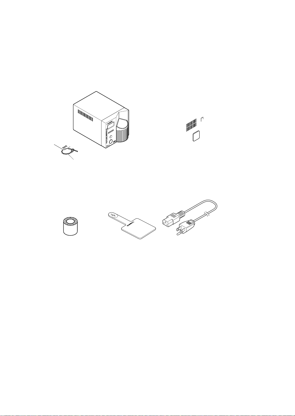
The front panel of the FM-202 soldering station
has four control buttons, the process gate, the
receptacle, and the card slot. The power switch
is on the back panel.
•Four control buttons:
–Initiates the Tip ID entry mode. When
pressed for less than one second, the
stored Tip ID is displayed. When pressed
for more than one second, the Tip ID
entry mode is activated.
–Initiates the temperature setting mode.
When pressed for less than one second,
the stored temperature is displayed.
When pressed for more than one
second, the temperature entry mode is
activated.
–Increases the value in the appropriate
display window.
–Decreases the value in the appropriate
display window.
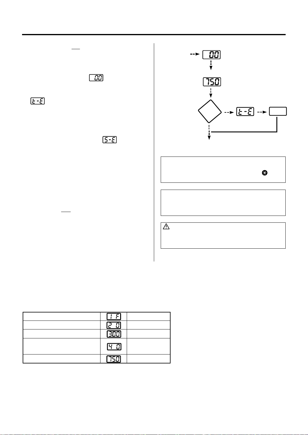
Displays
The FM-202 has a three-digit display element.
Depending upon the selected mode, it will
display:
•Normal mode:
Sensor temperature (tip temperature)
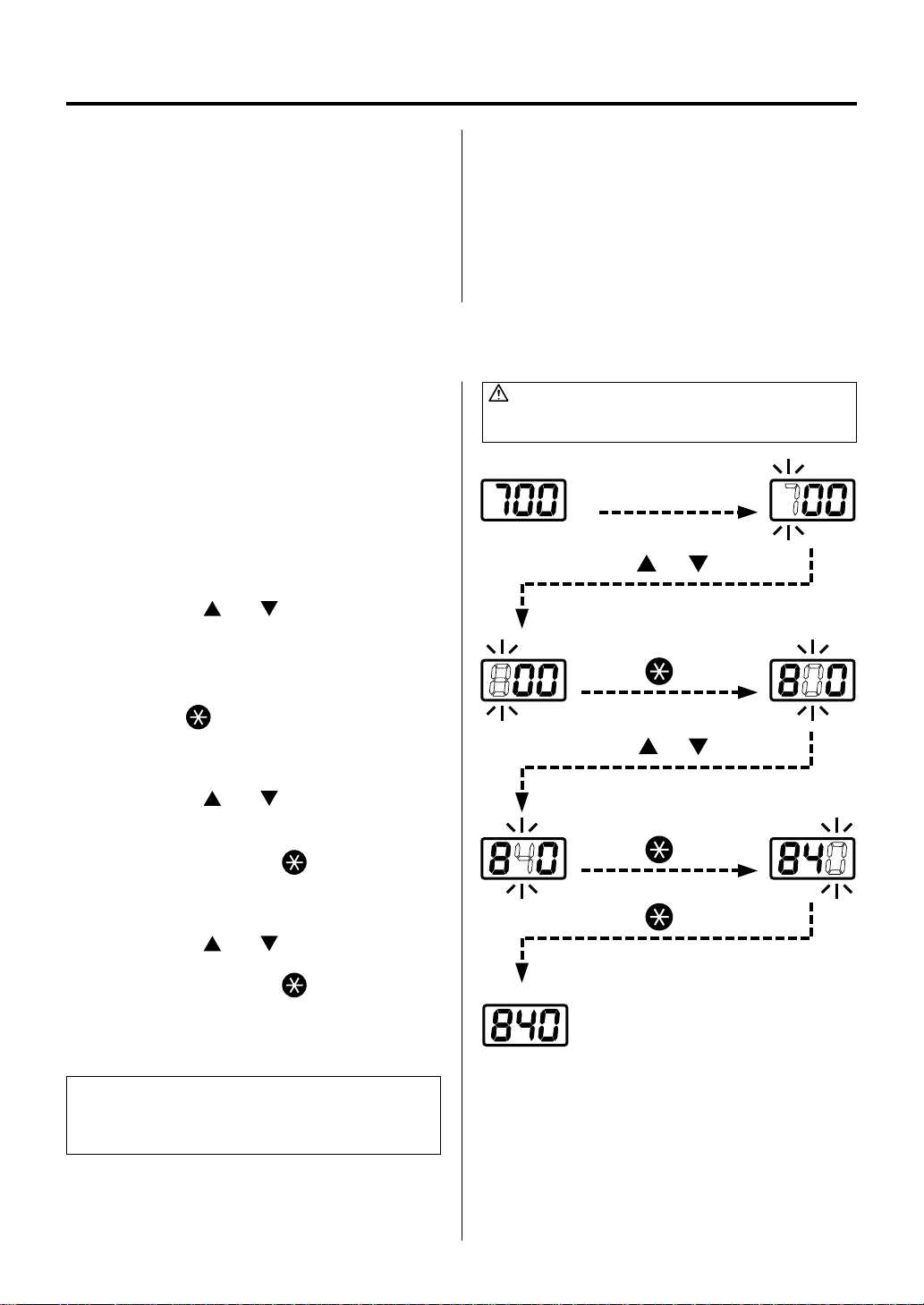
•Data entry:
Selected quantity (see ‘data entry procedures’
for exact characteristics)
•Temperature scale:
°C or °F, depending upon selection
•Error detection:
Refer to ‘ERROR MESSAGES’section
In addition, a single heater lamp will flash when
the station has reached the desired temperature,
indicating that it is ready for use.
An audible buzzer is provided to alert the
operator:
•When the station has reached the set tem-
perature. The buzzer will sound once.
•When the tip is inserted into the process gate,
the buzzer will sound once when the Tip ID
bar code has been read.
•When the low temperature threshold has
been crossed, the buzzer will sound
continuously. The buzzer will shut off once the
sensed temperature returns to the acceptable
range.
•When a foreign substance, an incompatible
tip, or the soldering end of the tip is inserted
into the FM-2021, the display will flash and
the buzzer will sound continuously.
•When the auto power shutoff is activated and
power to the heating element is turned off, the
buzzer will sound three times.
•When the process gate cannot read the Tip ID
bar code, the buzzer will sound three times.
•When a tip is inserted into the process gate
while the tip is already in the FM-2021, buzzer
will sound irregularly.
•When the tip is properly inserted into the
connector, the buzzer will sound once.
5