1
Packing List Please check to make sure that all the items listed below
are included in the HAKKO 701 package.
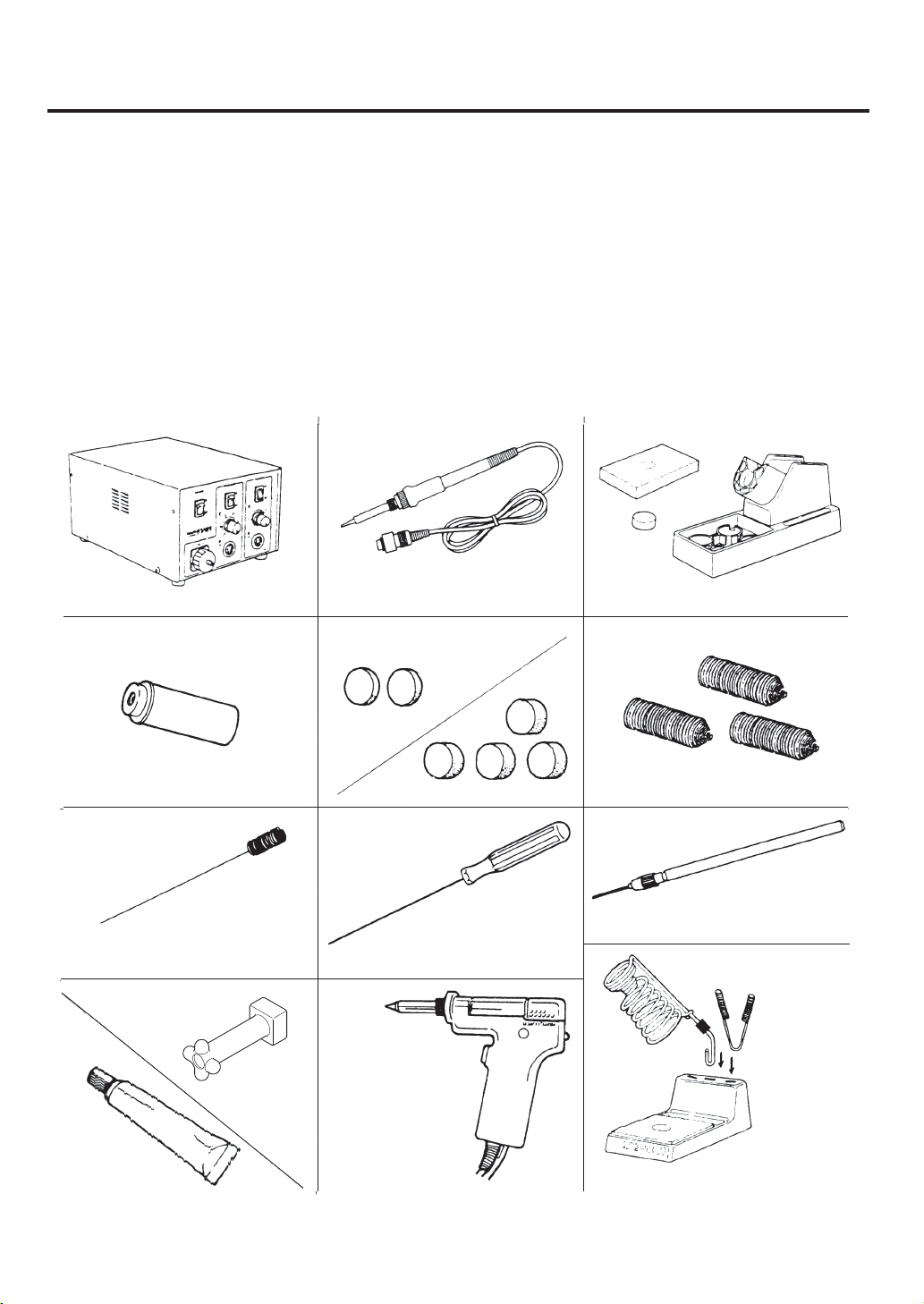
Station
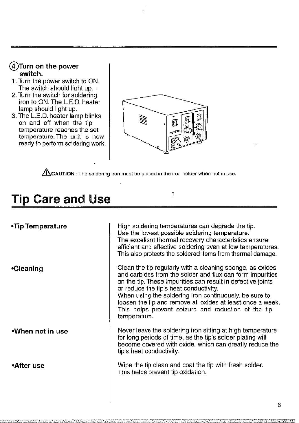
Soldering Iron
Desoldering Gun
Iron Holder for Soldering Iron
Iron Holder for Desoldering Gun
Filter Pipe
Ceramic Paper Filter (S)
Ceramic Paper Filter (L)
Spring Filter
Cleaning Pin (for ø1.0mm [0.04 in] nozzle)
Cleaning Pin (for Heating Element)
Cleaning Drill (for ø1.0mm [0.04 in] nozzle)
Silicone Grease
Wrench (for Desoldering Gun)
Instruction Manual
26
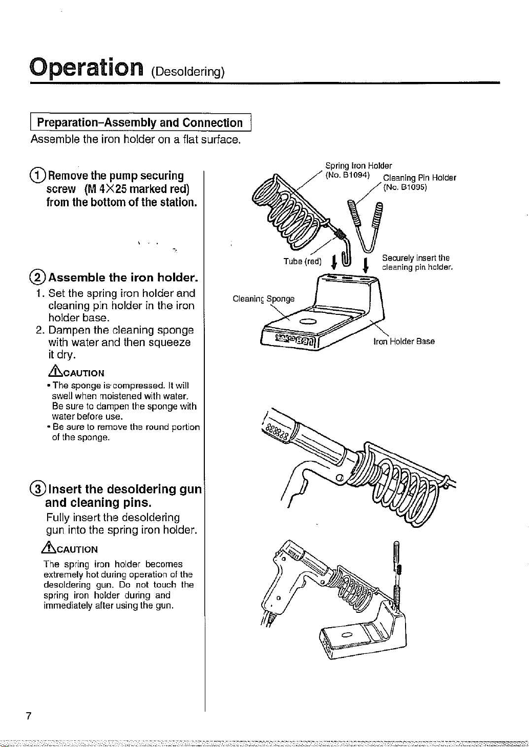
Station Soldering Iron Iron Holder for Soldering Iron
Filter Pipe
Ceramic Paper Filter (S)
Ceramic Paper Filter (L) Spring Filter
Cleaning Pin for ø1.0 mm (0.04 in) Nozzle
Cleaning Drill for ø1.0 mm (0.04 in) Nozzle
Cleaning Pin for Heating Element
Wrench
Iron Holder for
Desoldering Gun
Silicone Grease Desoldering Gun
*Never use it for
soldering iron.
..................................................1
........................................1
...................................1
...............1
...........1
.............................................1
....................................2
.....................................4
........................................................3
........1
....................1
.......1
..................................................1
...........................1
..............................................1
Specifications
Name
Power consumption
HAKKO 701
150W
Station
Part name
Part No.
Power consumption
Temperature
Nozzle to ground resistance
Nozzle to ground potential
Cord/Hose
Dimensions (W × H)
Weight (w/o cord, hose)
HAKKO 809
C1183
24V~ 50W
380℃- 480℃(716℉ - 896℉)
< 2 Ω
< 2mV (TYP. 1.2mV)
1.2m (4 ft.)
135×174 mm (5.31 × 6.85 in)
200g (0.44 lbs.)
Desoldering gun
• Specifications are subject to change without notice.
Part name
Part No.
Power consumption
Temperature range
Temperature stability
Tip to ground resistance
Tip to ground potential
Cord assembly
Total length
(w/o cord)
Weight (w/o cord)
HAKKO 907ESD
C1144
24V~ 50W
200℃- 480℃ / 392℉ - 896℉
±10℃/ ±18℉of the set temperature
±0.5℃/ ±0.9℉of tolerance at idling time
< 2 Ω
< 2mV (TYP. 0.6mV)
1.2m (4 ft.)
190mm (7.5 in.)
44g
(0.09 lbs.)
Soldering iron
1
2
3
4
Parts List (Iron/Iron Holder)
HAKKO 907ESD
Iron Holder
●Replacement Parts
øA
øB
øA
øB
No. A1002, A1003 No. A1004~A1007
1
2
3
4
5
6
7
8
9
10
11
Part No.
A1002
A1003
A1004
A1005
A1006
A1007
Part. Name / Specification
Nozzle S
ø0.8 mm (0.03 in )
Nozzle S
ø1.0 mm (0.04 in )
Nozzle ø0.8 mm (0.03 in )
Nozzle ø1.0 mm (0.04 in )
Nozzle ø1.3 mm (0.05 in )
Nozzle ø1.6 mm (0.06 in )
ø A
0.8 (0.03 in)
1.0 (0.04 in)
0.8 (0.03 in)
1.0 (0.04 in)
1.3 (0.05 in)
1.6 (0.06 in)
ø B
1.8 (0.07 in)
2.0 (0.08 in)
2.3 (0.09 in)
2.5 (0.1 in)
3.0 (0.12 in)
3.0 (0.12 in)
Part No.
B1215
B1086
B1087
B1088
B1089
B1302
B1303
B1304
B1305
A1028
Part. Name / Specification
Cleaning pin for Heating Element
Cleaning pin for ø0.8 mm (0.03 in) Nozzle
Cleaning pin for ø1.0 mm (0.04 in) Nozzle
Cleaning pin for ø1.3 mm (0.05 in) Nozzle
Cleaning pin for ø1.6 mm (0.06 in) Nozzle
Cleaning drill for ø0.8 mm (0.03 in) Nozzle
Cleaning drill for ø1.0 mm (0.04 in) Nozzle
Cleaning drill for ø1.3 mm (0.05 in) Nozzle
Cleaning drill for ø1.6 mm (0.06 in) Nozzle
Silicone grease
Item No.
1
2
3
4
Part Name
Iron holder
Iron receptacle
Iron holder base
Cleaning sponge
Part No.
C1142
B2021
B2019
A1042
Specifications
Sec. P. 13
Old part No.900M-H,900L-H
w/Handle Cover, E.S.D.
E.S.D.
Item No.
1
2
3
4
5
6
7
8
9
10
11
Part No.
B1784
B1786
B2022
B2032
A1321
B2028
B2024
B2027
B2031
B2030
Part Name
Nut
Tip enclosure
Soldering tip
Nipple
Grounding spring
Heating element
Terminal board
Handle
Handle cover
Cord bushing
Cord asse’y
Station
24V~
Vacuum pump,
double cylinder type
600mmHg (24in. Hg)
15ℓ/min.
190 × 250 × 130 mm
(7.48 × 9.84 × 5.12 in)
5.0 kg (11.02 lbs.)
Output
Vacuum generator
Vacuum pressure (Max)
Suction flow
Dimensions
(W × D × H)
Weight