Power Consumption
Temperature Range
Temperature Stability
Power Consumption
Tip to Ground Resistance
Tip to Ground Potential
Cord
Total Length (w/o cord)
Weight (w/o cord)
●HAKKO FM-2027
* The temperature was measured using the HAKKO FG-101
thermometer.
* This product is protected against electrostatic discharge.
* Specifications and design are subject to change without
notice.
Multi Rework Station
Instruction Manual
Thank you for purchasing HAKKO FM-206 Rework System.
Please read this manual before operating the HAKKO FM-206.
Keep this manual readily accessible for reference.
2. SPECIFICATIONS
3. WARNINGS, CAUTIONS, NOTES AND EXAMPLES
Warnings, cautions and notes are placed at critical points in this manual to direct the operator’s attention to
significant items. They are defined as follows:
WARNING: Failure to comply with a WARNING may result in serious injury or death.
CAUTION : Failure to comply with a CAUTION may result in injury to the operator, or damage to the
items involved.
NOTE: A NOTE indicates a procedure or point that is important to the process being described.
CAUTION
When power is ON, the tip will be hot. To avoid injury or damage to personnel and items in the work
area, observe the following:
●Do not touch the tip or the metal parts near the tip.
●Do not allow the tip to come close to, or touch, flammable materials.
●Inform others in the area that the unit is hot and should not be touched.
●Turn the power off when not in use, or left unattended.
●
Turn the power off when connecting the handpieces or storing the HAKKO FM-206.
●
This appliance is not intended for use by persons (including children) with reduced physical, sensory
or mental capabilities, or lack of experience and knowledge, unless they have been given supervision
or instruction concerning use of the appliance by a person responsible for their safety.
●
Children should be supervised to ensure that they do not play with the appliance.
●
To prevent accidents or damage to the HAKKO FM-206, be sure to observe the following:
●
Do not use the HAKKO FM-206 for applications other than soldering.
●
Do not strike the iron against hard objects to remove excess solder. This will damage the iron.
●
Do not modify the HAKKO FM-206.
●
Use only genuine Hakko replacement parts.
●
Do not allow the HAKKO FM-206 to become wet, or use it with wet hands.
●
Remove power and iron cords by holding the plug − not the wires.
●
Be sure the work area is well ventilated. Soldering produces smoke.
●
While using HAKKO FM-206, don’t do anything which may cause bodily harm or physical damage.
4. INITIAL SETUP
Jack**(1, 2, 3)
Power
Receptacle
Fuse
Power Switch
Control Button(1, 2, 3)
Filter Case Cover
■Part Names
Compatible with
FM-2024
FM-2026
FM-2027
FM-2032
Control Knob
Flow Control Knob
Air Output
Compatible with
FM-2022
FM-2023
FM-2024
FM-2026
FM-2027
FM-2030
FM-2031
FM-2032
Compatible with
FM-2024
FM-2026
FM-2027
FM-2029
FM-2030
FM-2031
FM-2032
* Each receptacle connector differs, please be careful not to connect an
incompatible device.
Errors will result.
**F
or connecting iron holders. Make sure to connect the correct holder.
While both vacuum and hot air can be used, only one can be operated at once. One
cannot use a combination of hot air and vacuum or two vacuums simultaneously.
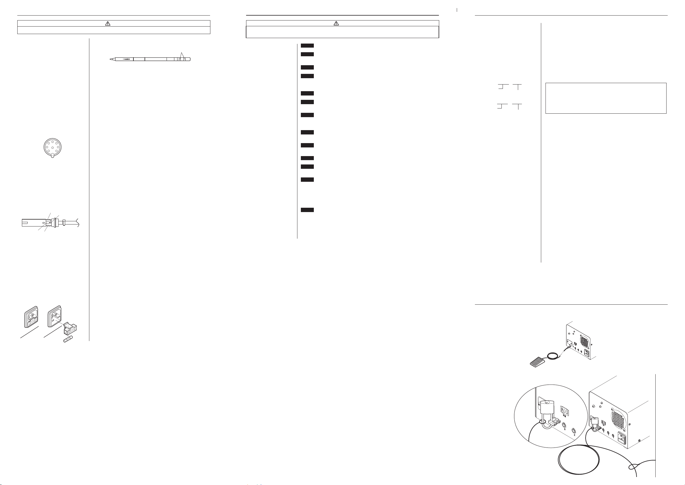
■Setup
●Hooking up the iron and connecting cable.
Connecting
Cable
Plug the iron's connector
cord into the receptacle.
Plug in power and connecting cables.
Power
Cable
•Please make sure the power is off when you plug in cables.
•Please make sure to hook up the connector cable and the iron holder on the same
channel and not to place the iron in a holder connected to a differing channel.
•Please take care not to mix up the hose connections, the MODEL FM-2024 connects
to the filter case cover and the HAKKO FM-2029 to the air output.
•Securely insert the connecting cable all the way in to the jack.
CAUTION
Connection for
FM-2024 Suction
Hose
Connection for
FM-2029 Air Hose
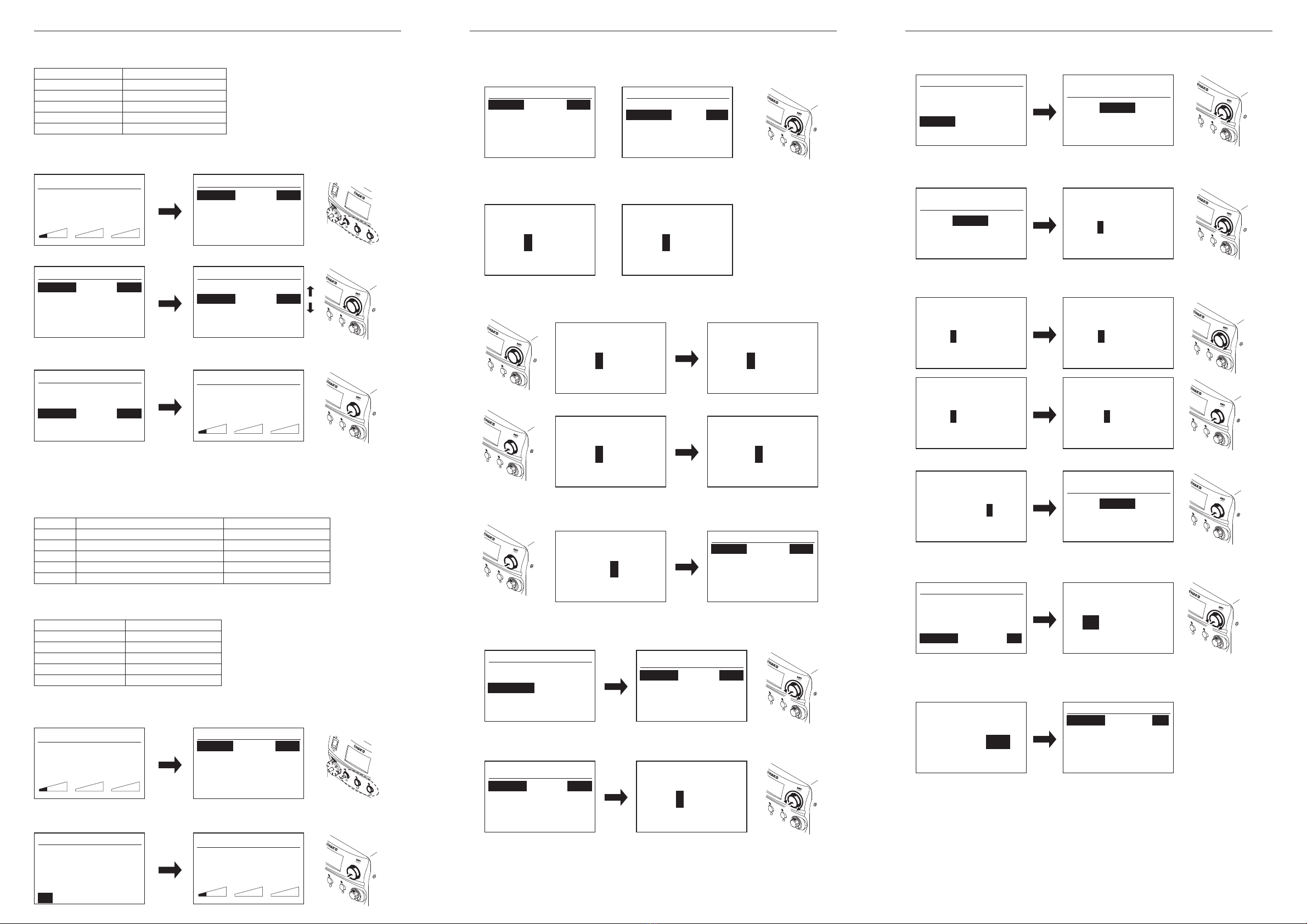
■Switch, Control
Button
and
Knob
Usage
Power switch
Use the power switch to turn
the power on and off.
Control Buttons
Use to change settings such as
temperature.
When pressed briefly:
Displays the preset screen.
When pressed and held:
Displays the change settings
screen.
Change Settings Screen Details
1. Temperature Settings
2. Offset Settings
3. Preset Temperature Settings
4. Preset Names
5. Channel Power (On/Off)
6 Exit
Control Knob Usage
Use to change settings
Turning the control knob:
Changes setting values
or moves the cursor
Pushing the control knob:
Makes selection
* If you press a control button while on the Preset or Change
Settings screen, the corresponding channel screen will be
displayed.
Plugged in irons will be heated according to the settings
when the power is turned on.
MAX 410W (450W)
HAKKO FM-2026/2027 200 - 450℃ (400 - 840℉)
MODEL FM-2022/2023 200 - 400℃ (400 - 750℉)
MODEL FM-2024 350 - 450℃ (660 - 840℉)
HAKKO FM-2029 100 - 550℃ (200 - 1030℉)
HAKKO FM-2030/2031 200 - 500℃ (400 - 930℉)
±5°C (±9°F) at idle temperature
70 W (24 V)
< 2 Ω
< 2 mV
1.2 m (4 ft)
188 mm (7.4 in.) with 2.4D tip
30 g (0.067 lb./1.07 oz.)with 2.4D tip
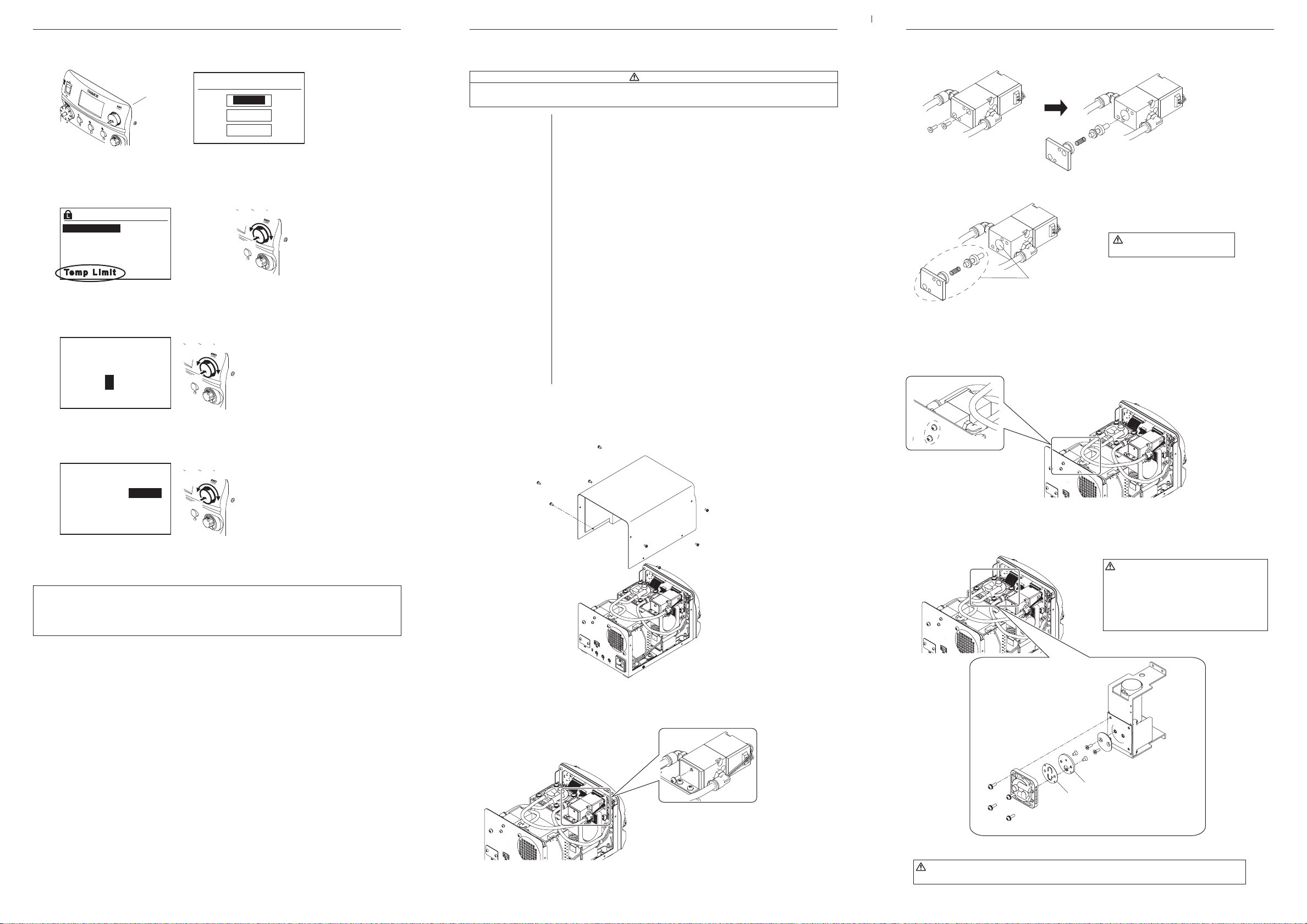
●Replacing the tip (HAKKO FM-2027)
The tip may be hot. Avoid holding the hot tip for a long time even if
using the heat-resistant pad. Otherwise burns may result.
CAUTION
Removing the tip:
●Hold down the lock release buttons in the sleeve assembly, pull out
the tip together with the sleeve assembly from the connector.
●While holding the front end of the sleeve assembly, pull out the tip.
• Be sure to keep the lock release buttons held down while pulling
out the sleeve assembly. Failure to do so will damage the locking
mechanism.
• Be sure to pull out the tip only after separating the sleeve assembly
from the connector. Otherwise, the sleeve assembly may fall down
and break.
CAUTION
Insert the tip:
●Reassemble in the reverse order of disassembly.
• Insert the tip into the sleeve assembly until it clicks into place. When
you hear it click, avoid forcing the tip into the sleeve assembly.
• When holding the head of the tip, there is a danger of burn. Be sure
to use the heat-resistant pad.
CAUTION
Output
Dimensions (W x H x D)
Weight
Capacity (Max)
Vacuum Generator
Vacuum Pressure (Max.)
Suction Flow
●Station
24V
162 × 136 × 245 mm (6.4 × 5.4 × 9.7 in)
6.2 kg (13.7 lb.)
6L/min.
Vacuum pump, cylinder type
80kpa (600 mm Hg) (24 in. Hg)
14L/min.
Instruction manual in the language of Japanese, English, Chinse, French, German and Korean
can be downloaded from the HAKKO Document Portal.
(Please note that some languages may not be available depending on the product.)
Flow Control Knob
When HAKKO FM-2029 is connected to
HAKKO FM-206, air flow will be displayed.
By turning the flow control knob, air flow
can be changed.
CH1 CH2 CH3
350
℃
Off
Ready
SOL
100%M
*Each Hakko handpiece with the exception of the HAKKO
FM-2027 has their own instruction manual. Please refer to
this manual for specifications and replacement parts.
Jack
(equipotential)
Receptacle* (1, 2, 3)
Jack
(for foot switch)
I/OCoverPlate
2014.7
MA02390XZ140723
CAUTION
Power consumption is different depending on
Standards.
1. PACKING LIST
Please check to make sure that all items listed
below are included in the package.
HAKKO FM-206
Power cord
Tip tray
Instruction manual
1
1
1
1
■Use this product with the following models.
HAKKO FM-2027 (Soldering Iron)
MODEL FM-2022 (Parallel Remover)
MODEL FM-2023 (Mini Parallel Remover)
MODEL FM-2024 (Desoldering Tool)
HAKKO FM-2026 (Soldering Iron N2 Type)
HAKKO FM-2029 (Hot Air Handpiece)
HAKKO FM-2030 (Heavy Duty Soldering Iron)
HAKKO FM-2031
(Heavy Duty Soldering Iron N2 Type)
HAKKO FM-2032 (Soldering Iron)
HAKKO FM-206
Power cord
Tip tray
*Each Hakko handpiece with the exception of the HAKKO
FM-2027 has their own instruction manual. Please refer to
this manual for specifications and replacement parts.
Copyright © 2013 HAKKO Corporation. All Rights Reserved.
連接部
隔離器
電路板
插座
電磁蓋
真空泵組件
螺釘
坦克組件
排出閥門
×
×
×
×
×
×
×
×
×
○
○
○
○
○
○
○
○
○
○
○
○
○
○
○
○
○
○
○
○
○
○
○
○
○
○
○
○
○
○
○
○
○
○
○
○
○
○
○
○
○
○
○
○
○
OVERSEAS AFFILIATES
U.S.A.: AMERICAN HAKKO PRODUCTS, INC.
TEL: (661) 294-0090 FAX: (661) 294-0096
Toll Free (800)88-HAKKO
4 2 5 5 6
http://www.hakkousa.com
HONG KONG: HAKKO DEVELOPMENT CO., LTD.
TEL: 2811-5588 FAX: 2590-0217
http://www.hakko.com.hk
SINGAPORE: HAKKO PRODUCTS PTE., LTD.
TEL: 6748-2277 FAX: 6744-0033
http://www.hakko.com.sg
Please access to the following address for the other Sales affiliates.
http://www.hakko.com
HEAD OFFICE
4-5, Shiokusa 2-chome, Naniwa-ku, Osaka 556-0024 JAPAN
TEL:+81-6-6561-3225 FAX:+81-6-6561-8466