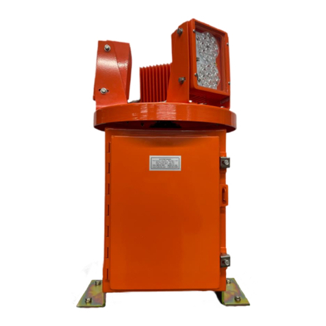
Hali-Brite HBM 150/2 L-801A Manual

Installation and Maintenance Manual
HBM 150/2
L-801A Airport Rotating Beacon
Hali-Brite®Inc.
1119 Madison St
Brainerd, MN 56401
Tel: 800.553.6269
Fax: 218.454.0972
www.halibrite.com
Copyright © 2020 Hali-Brite®Inc., Brainerd, MN, U.S.A. Printed in U.S.A. Rev. 10

2HBM 150/2 Installation and Maintenance Manual
Table of Contents
1Introduction................................................................................................................. 3
1.1 About this Manual............................................................................................... 3
1.2 Model Configurations......................................................................................... 3
1.3 Warranty ............................................................................................................. 3
1.4 Disclaimers ......................................................................................................... 4
2Safety Precautions....................................................................................................... 5
2.1 Safety Statements................................................................................................ 5
2.2 General Practices ................................................................................................ 5
2.3 Electrical Practices.............................................................................................. 6
2.4 Qualified Personnel............................................................................................. 7
2.5 Proper Usage....................................................................................................... 7
3Specifications.............................................................................................................. 8
3.1 Electrical and Optical Specifications.................................................................. 8
3.2 Physical Specifications ....................................................................................... 8
3.3 Environmental Specifications............................................................................. 8
4Installation................................................................................................................... 9
4.1 Unpacking........................................................................................................... 9
4.2 Tools and Supplies Needed................................................................................. 9
4.3 Installation........................................................................................................... 9
5Maintenance.............................................................................................................. 12
5.1 Maintenance Schedule ...................................................................................... 12
5.2 Maintenance Procedures................................................................................... 12
6Repair........................................................................................................................ 14
6.1 Cover Lenses..................................................................................................... 14
6.2 Fuses ................................................................................................................. 14
6.3 Timing Belt....................................................................................................... 14
6.4 Mercotac rotary electrical connector ................................................................ 14
6.5 Lamp Ballast..................................................................................................... 15
6.6 Motor and Gearhead ......................................................................................... 15
7Troubleshooting Chart, Replacement Parts and Wiring Diagrams........................... 17

HBM 150/2 Installation and Maintenance Manual 3
1Introduction
1.1 About this Manual
The information in this manual is provided to assist installation and maintenance
personnel in the proper installation, upkeep, and maintenance of the HBM 150/2
Airport Rotating Beacon. This manual also includes installation and maintenance
instructions for all equipment sold as options to the basic unit.
1.2 Model Configurations
L801A1116: 120 VAC, 60 Hz, Class I (-30C to +55C)
L801A1125: 220-240 VAC, 50 Hz, Class I (-30C to +55C)
L801A1126: 220-240 VAC, 60 Hz, Class I (-30C to +55C)
L801A1216: 120 VAC, 60 Hz, Class II (-55C to +55C)
L801A1225: 220-240 VAC, 50 Hz, Class II (-55C to +55C)
L801A1226: 220-240 VAC, 60 Hz, Class II (-55C to +55C)
1.3 Warranty
Hali-Brite®products are guaranteed against mechanical, electrical, and physical
defects (excluding lamps) for a period of one year from the date of installation
or a maximum of two years from the date of shipment and are guaranteed to be
merchantable and fit for the ordinary purposes for which such products are
made. Hali-Brite®will correct by repair or replacement, at its option, equipment
or parts which fail because of mechanical, electrical or physical defects, provided
that the goods have been properly handled and stored prior to installation,
properly installed and properly operated after installation, and provided further
that Buyer gives Hali-Brite®written notice of such defects after delivery of the
goods to Buyer. Hali-Brite®reserves the right to examine goods upon which a
claim is made. Said goods must be presented in the same condition as when the
defect therein was discovered. Hali-Brite®further reserves the right to require the
return of such goods to establish any claim. Hali-Brite’s obligation under this
guarantee is limited to making repair or replacement within a reasonable time
after receipt of such written notice and does not include any other costs such as
the cost of removal of defective part, installation of repaired product, labor or
consequential damages of any kind, the exclusive remedy being to require such
new parts to be furnished. Hali-Brite’s liability under no circumstances will exceed
the contract price of goods claimed to be defective. Any returns under this
guarantee are to be on a transportation charges prepaid basis. For products not
manufactured by, but sold by Hali-Brite®, warranty is limited to that extended by
the original manufacturer. This is Hali-Brite’s sole guarantee and warranty with
respect to the goods; there are no express warranties or warranties of fitness for
any particular purpose or any implied warranties of fitness for any particular
purpose or any implied warranties other than those made expressly herein. All

4HBM 150/2 Installation and Maintenance Manual
such warranties being expressly disclaimed. Details and values given in this
manual are average values and have been compiled with care. They are not
binding, however, and Hali-Brite®disclaims any liability for damages or
detriments suffered as a result of reliance on the information given herein or the
use of products, processes or equipment to which this manual refers. No
warranty is made that the use of the information or of the products, processes or
equipment to which this manual refers will not infringe any third party’s patents or
rights. The information given does not release the buyers from making their own
experiments and tests.
1.4 Disclaimers
This manual is published for informational purposes only and the information
provided should not be considered as all-inclusive or covering all contingencies.
If further information is required, Hali-Brite®Inc. should be contacted. Sale of the
product shown in this manual is subject to Hali-Brite’s terms and conditions
including, but not limited to, the Hali-Brite®Warranty. Such terms and conditions
are available upon request. Hali-Brite’s warranty will not apply to any products
which have been “so repaired or altered outside the manufacturer’s plants as, in
the manufacturer’s judgment, to affect its reliability and performance.”
No warranties, express or implied, including warranties of fitness for a particular
purpose or merchantability, or warranties arising from course or dealing or
usage of trade, are made regarding the information, recommendations, and
descriptions contained herein. The manufacturer is not responsible and will not
be held liable in contract or in tort (including negligence) for any special, indirect
or consequential damages, including injury or damage caused to vehicles,
contents or persons, by reason of the installation of any Hali-Brite®product or
its mechanical or electrical failure.

HBM 150/2 Installation and Maintenance Manual 5
2Safety Precautions
To help you install and maintain this equipment safely and efficiently make sure
you read and understand all safety information in this manual prior to performing
any procedure. Failure to do so may result in personal injury, property damage,
or possible death.
2.1 Safety Statements
The following safety statements are used throughout this manual. They will alert
you to possible safety hazards and conditions that could result in personal injury,
death, or property and equipment damage.
CAUTION: Indicates hazards or unsafe practices that could result in minor
personal injury, product, or property damage.
WARNING: Indicates hazards or unsafe practices that could result in
severe personal injury or death.
DANGER: Indicates immediate hazards that will result in severe personal
injury or death.
2.2 General Practices
Read and become familiar with the general safety instructions provided in this
section of the manual before installing, operating, maintaining, or repairing this
equipment.
• Do not attempt to assemble or install this equipment if it has been damaged
from shipping.
• Do not attempt to install or maintain this equipment if you or the equipment is
standing in water.
• Only qualified personnel should perform maintenance on this equipment.
• Always use proper tools (as mentioned in this manual) to perform installation
and maintenance.
• Use proper hand and eye protection as needed when installing or maintaining
this equipment.
• Make sure you have adequate first aid supplies available when installing this
equipment.

6HBM 150/2 Installation and Maintenance Manual
• Do not modify this equipment as this could create a safety hazard and void your
Hali-Brite®warranty.
• Use only Hali-Brite®replacement parts.
• Read and carefully follow the instructions given throughout this manual for
performing specific tasks and working with specific equipment.
• Follow all applicable safety procedures required by your company, industry
standards, and government or other regulatory agencies.
• Make sure all equipment is rated and approved for the environment in which
you are using it.
• Follow all instructions for installing components and accessories.
• Protect components from damage, wear, and harsh environment conditions.
• Allow ample room for maintenance, wiring accessibility, and cover removal.
2.3 Electrical Practices
• Do not attempt to make electrical connections with the power on.
• Disconnect and lock out electrical power before touching any electrical
connections.
• Install all electrical connections to local code.
• Use only electrical wire of sufficient gauge and insulation to handle the rated
current demand. All wiring must meet local codes.
• Route electrical wiring along a protected path. Make sure moving equipment will
not damage it.
• Protect equipment with safety devices as specified by applicable safety
regulations.
• If safety devices must be removed for installation, install them immediately after
the work is completed and check them for proper functioning.
• Always use rated electrical tools when performing electrical work.
• Always make sure electrical connections are tight.
• Make sure electrical covers are in place after installation.

HBM 150/2 Installation and Maintenance Manual 7
• Do not touch hot lamps with bare hands.
2.4 Qualified Personnel
Qualified personnel are those that are trained and experienced with installing or
maintaining Hali-Brite®equipment. Only qualified personnel should install or
maintain Hali-Brite®equipment and auxiliary features.
No one should:
• Attempt to install or perform maintenance on this or any Hali-Brite®equipment
if they are physically impaired or under the influence of alcohol or non-
prescription drugs.
• Maintain or install this equipment without correct training, supervision or
experience in mechanical or electrical equipment.
• Attempt to maintain or install this equipment without the correct tools as
specified in this manual.
2.5 Proper Usage
Always use this equipment as specified in this manual. Improper usage may
result in serious personal injury, property damage, or possible death.
• Do not make any modifications that have not been recommended by Hali-
Brite®.
• Do not use any replacement parts that are not purchased from Hali-Brite®.
• Hali-Brite®cannot be responsible for injuries or damages resulting from
nonstandard, unintended applications of its equipment. This equipment is
designed and intended only for the purpose described in this manual. Uses not
described in this manual are considered unintended uses and may result in
serious personal injury, death, or property damage.

8HBM 150/2 Installation and Maintenance Manual
3Specifications
3.1 Electrical and Optical Specifications
FAA Type ......................................................L-801A
Input Voltage..................................................120 or 220-240VAC, +/-10%, 50/60
Hz
Power Consumption.......................................395W (Class I), 795W (Class II)
Lenses...........................................................One clear, one green
Lamps.............................................................150W Metal Halide, Pulse Start
Rated Average Lamp Life ...................12,000 hours
Beam Intensity ....................................25,000 min. effective candelas from
+1° to +2° vertical and from +8° to +10° vertical, 50,000 min. effective
candelas from +2° to +8
Rotation Speed ..............................................12 RPM (Produces 24 flashes per
minute)
3.2 Physical Specifications
Dimensions ....................................................Height: 30 inches (762 mm)
........................................................................Width: 20 inches (508 mm)
Mounting Dimensions....................................Four ½ inch (12.7 mm) holes in a
rectangular pattern: (4"x 16") (101.6 x 406.4 mm)
Product Weight...............................................75 lb. (34 kg)
Shipping Weight ............................................175 lb. (79.5 kg)
3.3 Environmental Specifications
Operating Temperature (Class I) ...................-30C (-22F) to +55C (+131F)
Operating Temperature (Class I) ...................-55C (-67F) to +55C (+131F)
Heater (Class II only)......................................400W (heating element)
Turns On ....................... .....................Below 0°C (+32°F)
Humidity ...................................... ..................0% to 100%
Altitude .......................................... ................Sea level to 10,000 feet (3000 m)
Wind................................................................Velocities to 100 mph (161 km/h)

HBM 150/2 Installation and Maintenance Manual 9
4Installation
WARNING: Allow only qualified personnel to perform the following tasks.
Observe and follow the safety instructions in this document and all other
related documentation.
4.1 Unpacking
Handle equipment very carefully to prevent component damage. Note any
exterior damage to the carton/crate that might lead to detection of equipment
damage. Open the top of the carton/crate. Remove foam packing from the top of
the box. Carefully lift the unit out of the box.
CAUTION: Do not lift the unit by the head. Failure to observe this warning
may result in equipment damage.
Unpack the carton/crate upon receipt and check the contents and their condition.
If you note any damage to any equipment, file a claim with the carrier
immediately. The carrier may need to inspect the equipment.
4.2 Tools and Supplies Needed
Equipment Required But Not Supplied
Wrenches
Set of Screwdrivers
Set of Pliers
Voltmeter
Insulation Tester
Level
Lightning Rod
Ground Wire (for lightning rod)
Liquid Glass Cleaner
S0-3 Cable, AWG 12, liquid-tight conduit and connectors
4.3 Installation
The HBM 150/2 rotating beacon comes completely assembled except for
installation of a customer-supplied AWG 12, S0-3 power cord.
4.3.1 Mounting
Open the front door on the cabinet. Inspect the interior to make sure all parts are
tight and have not been loosened in shipment. Close the door and tighten the
latches.

10 HBM 150/2 Installation and Maintenance Manual
Determine the beacon mounting location, and drill four ½” holes in the platform,
spaced as shown in Figure 1.
Figure 1
If the surface is not level, spacers or shims will be needed. Place a level on top
of the weather cap and use shims as necessary under the four corners to bring
the beacon to level. Install and tighten the mounting bolts, four each #1/2-13
bolts, length as required.
4.3.2 Wiring
See Figure 2 to locate the power connection point. The power cord enters the
beacon chassis through the hole in the base, and attaches to the white terminal
block in the lower right corner.
Figure 2

HBM 150/2 Installation and Maintenance Manual 11
To install power cord, perform the following procedure:
1. Unscrew the two door latches and open the chassis door.
2. Route the cable through the hole in the bottom of the chassis. Install a ½”
liquid-tight conduit fitting in the chassis hole.
3. Connect the power cord at the terminal strip as follows: Attach the black
wire (120 VAC) to the terminal marked , the white wire (neutral) to the
terminal marked N, and the green wire (ground) to the terminal marked G.
4.3.3 Optional Heater Wiring
The optional heater assembly consists of a 400-watt heating element and
thermostat. The heater assembly should be connected through a power cord to
a separate circuit breaker, so that it may remain operable when the beacon is
turned off. The circuit breaker should be switched off during the summer months.
When the temperature drops below +32°F (0°C), the thermostat activates the
heater, which is attached to the motor gearbox. The gearbox lubricant is warmed
and this facilitates rotation of the beacon when it is energized.
The power connections for the heater are located on the same terminal block as
the main beacon power connections. Attach the black wire (120 VAC) to the
terminal marked C, the white wire (neutral) to the terminal marked N, and the
green wire (ground) to the terminal marked G.
4.3.4 Beam Angle Adjustment
All beacons are shipped from the factory preset at an elevation angle of 5
degrees, per FAA requirements. To adjust to a different angle, refer to Section
5.2.2.

12 HBM 150/2 Installation and Maintenance Manual
5Maintenance
5.1 Maintenance Schedule
Interval Task
Daily Inspect for lamp failure and proper rotation.
Bi-monthly Inspect cleanliness of glass. Clean as necessary.
Annually Inspect all electrical connections.
Replace beacon lamps at 12,000 hours.
5.2 Maintenance Procedures
5.2.1 Lamp Replacement
WARNING: The lens temperature can be as high as 373 °F
(189 °C). Allow one-half hour for the lamps to cool before
opening the lens cover. Failure to observe this warning may
result in personal injury or equipment damage.
1. Disconnect and lock out power to the beacon.
2. The beacon head cover has either (a) one screw and a hinge, or (b) two
screws. Loosen the head cover screw(s) located at the edge of the head
cover, and open or remove the head cover.
3. Remove the lamp by pulling it straight out of the socket.
4. Clean the reflector with glass cleaner.
5. Clean the new lamp with glass cleaner. After cleaning, do not touch the
glass with your fingers.
6. Install the lamp by pushing it straight into the socket. Take care not to rub
the edge of the reflector.
7. Close or replace the head cover, and tighten the screw(s).
8. Repeat as necessary for the other head.
5.2.2 Beam Angle Adjustment
All beacons are shipped from the factory preset at an elevation angle of 5
degrees, per FAA requirements.
To adjust the beacon beam to a different angle, perform the following procedure:
1. The beacon head cover has either (a) one screw and a hinge, or (b) two
screws. Loosen the head cover screw(s) located at the edge of the head
cover, and open or remove the head cover.

HBM 150/2 Installation and Maintenance Manual 13
2. Locate the beam elevation label on the top inside edge of the head, near
the edge of the reflector.
3. Loosen the two #10 Phillips-head screws located at the left and right
outside edge of the head. Do not loosen them more than 2 turns.
4. Loosen the #10 Phillips-head screw located at the top outside edge of the
head, directly above the beam elevation label. Do not loosen it more than
2 turns.
5. The beam angle may now be adjusted by gently pressing on the top and
bottom edges of the reflector. Adjust the reflector until the pointer
indicates the desired elevation on the elevation label.
6. Tighten the #10 Phillips-head screw located at the top outside edge of the
head.
7. Tighten the two #10 Phillips-head screws located at the left and right
outside edges of the head.
8. Close or replace the head cover, and tighten the screw(s).
9. Repeat Steps 1-8 for the other head.
5.2.3 Lens Cleaning
Clean lenses periodically with alcohol or glass cleaner and soft cloth. Wipe
dry with a clean soft cloth.
5.2.4 Lubrication
All moving parts are permanently lubricated and will not require further
attention.

14 HBM 150/2 Installation and Maintenance Manual
6Repair
6.1 Cover Lenses
Cover lenses are replaced as follows:
1. Locate the four metal clips located at the edges of the lens.
2. Remove the screw from each of the four clips.
3. Lift the lens out of the head cover.
4. Install the new lens in the head cover.
5. Install the four metal clips at the edges of the lens.
6.2 Fuses
The HBM 150/2 has a lamp fuse, and a motor fuse. The fuses are located on the
Control Panel, directly inside the door of the chassis.
6.3 Timing Belt
To replace the timing belt:
1. Disconnect and lock out power to the beacon.
2. Disconnect the two lamp wires from the control panel. Refer to Section 7
for the wiring diagram.
3. Loosen the four screws on the motor, with a 5/32” Allen wrench and 3/8”
wrench.
4. Slide the motor to the right and remove the old belt.
5. Install the new belt.
6. Tighten the belt by sliding the motor to the left. The belt should have 1/8”
deflection. Do not over tighten the belt.
7. Reconnect the two lamp wires to the control panel.
8. Reconnect power to the beacon.
6.4 Mercotac rotary electrical connector
Perform the following steps to replace the mercotac rotary electrical
connector:
1. Disconnect and lock out power to the beacon.
2. Disconnect the two lamp wires from the control panel. Refer to Section 7
for the wiring diagram.
3. Remove the two wires from the bottom of the coupling.
4. Loosen the cap screw in torque arm, and remove the torque arm.
5. Loosen the setscrew in the bottom of the main shaft, and remove the
mercotac rotary electrical connector.

HBM 150/2 Installation and Maintenance Manual 15
6. Remove the two wires from the top of the mercotac rotary electrical
connector.
7. Place the black wire on the center tab of the new mercotac rotary
electrical connector, and place the white wire on the outer tab of the new
mercotac rotary electrical connector.
8. Reinsert the mercotac rotary electrical connector in the shaft, and tighten
the setscrew. (NOTE: Do not over tighten.)
9. Reinstall the torque arm, and tighten the cap screw. (NOTE: Do not over
tighten.)
10.Place the black wire on the center tab of the mercotac rotary electrical
connector, and the white wire on outer tab of the mercotac rotary electrical
connector.
11.Connect the two wires to the control panel. Make sure they are connected
to the original terminals. (NOTE: The black wire connects to the upper
terminal, and white wire connects to the lower terminal.)
12.Reconnect power to the beacon.
13.The Mercotac rotary electrical connector contains a small amount of
mercury. It should be returned to the manufacturer for recycling, using the
form located at the back of this manual.
6.5 Lamp Ballast
To replace a lamp ballast, perform the following steps:
1. Disconnect and lock out power to beacon.
2. Open the cabinet door.
3. Refer to the wiring diagrams in Section 7 to locate the connections.
Disconnect the ballast input power leads at the terminal block.
4. Remove the ballast output wires at the terminal block.
5. Remove the two ¼-20 bolts and nuts attaching the ballast assembly to the
main shaft, and remove the old ballast.
6. Place the new ballast into position on the main shaft.
7. Replace the two ¼-20 bolts to attach the ballast assembly to the main
shaft.
8. Reconnect the ballast input power wires to the terminal block. (NOTE:
Black wire on terminal labeled , and white wire on terminal labeled N.)
9. Reconnect the ballast output wires to the terminal block.
10.Reconnect the power to the beacon.
6.6 Motor and Gearhead
1. Disconnect and lock out power to the beacon.
2. Refer to the wiring diagrams in Section 7 for component connections.
3. Loosen the four cap screws that hold the motor in place, and slide the
motor to the right.
4. Remove the timing belt.

16 HBM 150/2 Installation and Maintenance Manual
5. Remove the setscrews in the motor gear, and remove the gear. (NOTE:
There are two setscrews in each hole.)
6. Disconnect the motor black wire from control panel.
7. Disconnect the wires from the capacitor.
8. Remove the nuts from the four motor cap screws.
9. Remove the motor and gearbox.
10.If replacing only the motor, separate the old motor from the gearbox, and
replace with the new motor.
11.If replacing only the gearbox, separate the gearbox from the motor, and
replace with the new gearbox.
12.Install the new motor and gearbox back on to motor plate with the four
cap screws and nuts.
a. (NOTE 1: Make sure the shaft of the gearbox is to the right.)
b. (NOTE 2: Make sure the wires of the motor are facing out.)
13.Reinstall the gear on the shaft of the gearbox, and tighten the setscrews.
14.Reinstall the belt on the two gears, and tighten the belt by sliding the
motor to the left, and tighten the cap screws and nuts. (NOTE: Adjust the
timing belt for no more than 1/8” deflection.)
15.Reconnect the wires to the motor capacitor. Red wire on the left side, and
the two white wires on the right side.
16.Reconnect the black wire to the neutral on control panel.
17.Reconnect the power to the beacon.

HBM 150/2 Installation and Maintenance Manual 17
7 Troubleshooting Chart,
Replacement Parts and
Wiring Diagrams
Beacon Troubleshooting Chart
This chart will help you to locate over 99% of beacon problems. Detailed repair
procedures are located in chapter 6 of this manual.
If you are still unable to solve the problem, call Hali-Brite at 800-553-6269.
No Yes
No
Yes
Yes
No
No
No
No
Start
Beacon rotates?
Lamps operate?
Lamp and motor
fuses blown, or no
power from source
Motor fuse blown?
Timing belt broken?
Replace motor
Both lamps failed?
Replace
lamp fuse
Replace lamp.
Does it work?
Replace lamp
ballast assembly

18 HBM 150/2 Installation and Maintenance Manual
Replacement Parts
Ref
Part Number
Description
1
0200-0024
230VAC 50 Hz Ballast Assembly
2
0200-0023
120/240VAC 60 Hz Ballast Assembly
3
0600-0003
Timing Belt
4
2300-0002
Motor Fuse, ½ amp, 3AG, slow-blow
5
2300-0010
Lamp Fuse, 6.25 amp, 3AG, slow-blow
6
3400-0125B
Lamp, 150 watt pulse start, GE 20017
7
2800-0006
Lens, Clear
8
2800-0043
Lens, Green
9
1500-0011
Lens Clip
10
1800-0000
Mercotac rotary electrical connector
11
4100-0000-1A
HBM150 MOTOR
INSPECTEDBY: __________________________
QUALITY CONTROL, ACCEPTANCE
DESCRIPTION:
DATE:
SERIAL #:
PRODUCT:
HALI-BRITE. INC.
Airport Equipment
Qualified to FAA
Specification
Intertek Testing Services N.A., Inc.
1
2
3
4
5
6
7
8
9999
10
10
6


Table of contents
Other Hali-Brite Security System manuals