14 15
17
24 2522 23
4
3
12
20 2118 19
5
30
3
1
4
2
25
17
22
23
24
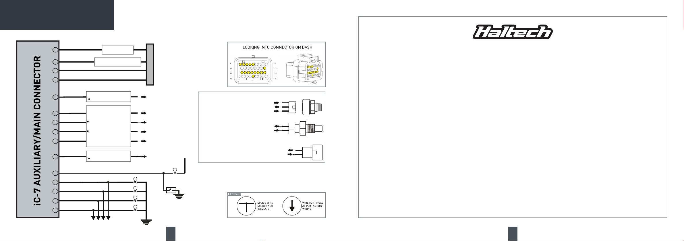
+12V SWITCHED
BATTERY GROUND
CANHIGH
CANLOW
Ground
PARKINGLIGHTS
LEFT TURN
RIGHTTURN
HIGH BEAM
HANDBRAKE
+12V
Ground
HANDBRAKESWITCH
3
2
1
4
21
18
19
20
AVI 1
AVI 2
AVI 3
AVI 4
INPUT: 0 TO 5V
4 X ANALOG VOLTAGEINPUTS
AVI
AVAILABLEFUNCTIONS IN
CAN BE ALLOCATEDTO
THESOFTWARE
USER DEFINABLEINPUTS
TO 5V
INDIVIDUAL SOFTWARE
SELECTABLE 1K PULL-UP
5+5V SUPPLY+5V SENSOR SUPPLY
200mA MAX OUTPUT CURRENT
30 GNDOUTPUTGROUND OUTPUT
GND OUTPUT FOR SENSORS
FROM IGN SWITCH OR
CAN CABLE
CONNECT TO BATTERY NEGATIVE
OR CAN CABLE
MAIN CONNECTORPIN 18/19/20/21 (AVI)
MAIN CONNECTORPIN 5 (+5VSENSOR SUPPLY)
MAIN CONNECTOR PIN 30 (GROUNDOUTPUT)
MAIN CONNECTORPIN 18/19/20/21 (AVI)
MAIN CONNECTOR PIN 30 (GROUND OUTPUT)
MAIN CONNECTORPIN 18/19/20/21 (AVI)
MAIN CONNECTOR PIN 30 (GROUND OUTPUT)
MAIN CONNECTORPIN 18/19/20/21 (AVI)
MAIN CONNECTORPIN 30 (GROUNDOUTPUT)
MAIN CONNECTORPIN 18/19/20/21 (AVI)
MAIN CONNECTORPIN 30 (GROUNDOUTPUT)
PRESSURE SENSORS
TEMPERATURE SENSORS
FUEL LEVEL SENSORS
17
24 2522 23
4
3
12
20 2118 19
5
30
3
1
4
2
25
17
22
23
24
+12V SWITCHED
BATTERY GROUND
CANHIGH
CANLOW
Ground
PARKINGLIGHTS
LEFT TURN
RIGHTTURN
HIGH BEAM
HANDBRAKE
+12V
Ground
HANDBRAKESWITCH
3
2
1
4
21
18
19
20
AVI 1
AVI 2
AVI 3
AVI 4
INPUT: 0 TO 5V
4 X ANALOG VOLTAGEINPUTS
AVI
AVAILABLEFUNCTIONS IN
CAN BE ALLOCATEDTO
THESOFTWARE
USER DEFINABLEINPUTS
TO 5V
INDIVIDUAL SOFTWARE
SELECTABLE 1K PULL-UP
5+5V SUPPLY+5V SENSOR SUPPLY
200mA MAX OUTPUT CURRENT
30 GNDOUTPUTGROUND OUTPUT
GND OUTPUT FOR SENSORS
FROM IGN SWITCH OR
CAN CABLE
CONNECT TO BATTERY NEGATIVE
OR CAN CABLE
MAIN CONNECTORPIN 18/19/20/21 (AVI)
MAIN CONNECTORPIN 5 (+5VSENSOR SUPPLY)
MAIN CONNECTOR PIN 30 (GROUNDOUTPUT)
MAIN CONNECTORPIN 18/19/20/21 (AVI)
MAIN CONNECTOR PIN 30 (GROUND OUTPUT)
MAIN CONNECTORPIN 18/19/20/21 (AVI)
MAIN CONNECTOR PIN 30 (GROUND OUTPUT)
MAIN CONNECTORPIN 18/19/20/21 (AVI)
MAIN CONNECTORPIN 30 (GROUNDOUTPUT)
MAIN CONNECTORPIN 18/19/20/21 (AVI)
MAIN CONNECTORPIN 30 (GROUNDOUTPUT)
PRESSURE SENSORS
TEMPERATURE SENSORS
FUEL LEVEL SENSORS
iC-7 WIRING DIAGRAM
At Haltech we make every effort to design and manufacture fault-free products
that perform up to or above the market expectations. All our products are covered
by a Limited 12 Month Warranty.
Haltech Limited Warranty
Unless specied otherwise, Haltech warrants its products to be free from defects in material or
workmanship for a period of 12 months from the date of purchase.
If the Haltech product is found to be defective as mentioned above, it will be replaced or repaired
if returned prepaid along with proof of purchase. Proof of purchase in the form of a copy of the
original purchase invoice, receipt or bill of sale which indicates that the product is within the
warranty period, must be presented to obtain warranty service.
Replacement or repair of a defective product shall constitute the sole liability of Haltech. To
the extent permitted by law, the foregoing is exclusive and in lieu of all other warranties or
representations, either expressed or implied, including any implied warranty of merchantability or
tness. In no event shall Haltech, be liable for special or consequential damages.
Product Returns
Please include a copy of the original purchase invoice, receipt or bill of sale along with the
unused, undamaged product and its original packaging. Any product returned with missing ac-
cessory items or packaging will incur extra charges to return the item to a re-saleable condition.
All product returns must be sent via a freight method with adequate tracking, insurance and proof
of delivery services. Haltech will not be held responsible for product returns lost during transit.
Returns of Products Supplied in Sealed Packaging
The sale of any sensor or accessory supplied in sealed packaging is strictly non-refundable
if the sealed packaging has been opened or tampered with. This will be clearly noted on the
product packaging. If you do not accept these terms please return the sensor in its original un-
opened packaging within 30 days for a full refund.
A sensor or accessory product may be returned after 30 days of purchase (with its sealed pack-
aging in tact) for credit only (no refunds given) and will be subject to a 10% restocking fee.
Installation of Haltech Products
No responsibility whatsoever is accepted by Haltech for the tment of Haltech Products. The
onus is clearly on the installer to ensure that both their knowledge and the parts selected are cor-
rect for that particular application. Any damage to parts or consequential damage or costs result-
ing from the incorrect installation of Haltech products are totally the responsibility of the installer.
Always disconnect the battery when doing electrical work on your vehicle. Avoid sparks, open
ames or use of electrical devices near ammable substances. Do not run the engine with a
battery charger connected as this could damage the ECU and other electrical equipment.
Do not overcharge the battery or reverse the polarity of the battery or any charging unit. Discon-
nect the Haltech ECU from the electrical system whenever doing any welding on the vehicle by
unplugging the wiring harness connector from the ECU.
After completing the ECU installation, make sure there is no wiring left un-insulated. Uninsulated
wiring can cause sparks, short circuits and in some cases re. Before attempting to run the en-
gine ensure there are no leaks in the fuel system.
All fuel system components and wiring should be mounted away from heat sources, shielded
if necessary and well ventilated. Always ensure that you follow workshop safety procedures. If
you’re working underneath a jacked-up car, always use safety stands!
____________________________________________________________________________
Haltech Off-Road Usage Policy
In many states it is unlawful to tamper with your vehicle’s emissions equipment. Haltech products
are designed and sold for sanctioned off-road/competition non-emissions controlled vehicles
only and may never be used on a public road or highway.
Using Haltech products for street/road use on public roads or highways is prohibited by law un-
less a specic regulatory exemption exists (more information can be found on the SEMA Action
Network website www.semasan.com/emissions for state by state details in the USA).
It is the responsibility of the installer and/or user of this product to ensure compliance with all
applicable local and federal laws and regulations. Please check with your local vehicle authority
before purchasing, using or installing any Haltech product.
WARRANTY CERTIFICATE