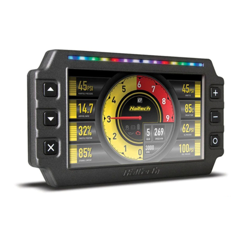
Haltech ic-7 User manual

1
DISPLAY DASH
QUICK START GUIDE

IC-7 DISPLAY DASH OVERVIEW
What’s in the box?
• 1 x Haltech IC-7 Display Dash
• 1 x HT-131001 34 Pin Main Connector Harness
• 1 x HT-130028 DTM-4 to DTM-4 CAN
Extension Cable (3.0m)
• 1 x HT-070013 USB to M5 Right Angle (400mm)
2
This quick start guide will walk you through the
installation of a Haltech IC-7 Display Dash into
a vehicle already fitted with a Haltech ECU.
This guide is accompanied by the Help
information located in the Haltech IC-7
software, located on the USB key provided.
More information is available from the Haltech
website: www.HALTECH.com
• 1 x HT-070001 USB Cable 2.0M
• 3 x M5 x 8mm Mounting Screws
• 1 x USB Key
• 1 x Quick Start Guide Booklet
• 1 x Haltech Product Catalogue
Optional Mounting Options (purchased separately)
Mounting Bracket
with Integrated Visor
HT-060071
Mounting Bracket
HT-060070

3
IC-7 DISPLAY DASH OVERVIEW
FRONT VIEW
1 Display Screen
2 Control Buttons
3 Shift / Alarm Light Panel
4 Ambient Light Sensor
REAR VIEW
5 Comms Connector
6 Auxiliary Connector
7 Mounting Screw Holes

4
Screen Navigation
Three keys perform the screen navigation.
• Press . key to go back to the previous
screen in the sequence.
• Press , key to go to the next screen
in the sequence.
• Press O to go to the home (default)
screen.
When the dash is powered up it will display
a Haltech Logo Screen. After an initial
configuration time the dash will display the
default home screen.
You can choose from a number of display
layouts available in the Haltech IC-7 software.
Display channels are user-customisable.
Brightness Control
The dash has an ambient light sensor placed in
the light bar to detect ambient light conditions.
In addition, the dash has a manual brightness
control which alters the range of the ambient
light sensor.
There are five brightness settings. On minimum
brightness setting, the display is at its minimum
brightness when the environment is dark, and
the brightness of the display increases as the
environment becomes brighter.
On the maximum brightness setting, the display
is always at full brightness regardless of the
ambient light level.
The default setting is brightness level 3.
Press the = key to increase the brightness
level by 1.
Press the - key to decrease the brightness
level by 1.
Shift / Alarm Lights
The default function of the shift / alarm light
panel is as a shift light bar, however alarms can
be progremmed for any channel in the IC-7.
There are 14 lights in the sequence.
Each LED has a threshold to trigger, and a
colour which it lights up when the RPM exceeds
the threshold.
The colours available are red, green, blue and
their combinations (yellow, cyan, magenta and
white).
Alarms are configured using the Haltech IC-7
software. When an alarm event occurs, a
message will appear on the screen.
The lights on the light bar can be set to flash in
a preset colour.
When an alarm is triggered there are two
options of turning it off:
1. Press the x key to acknowledge the alarm.
2. Pre-set your alarm to turn off automatically
when the alarm condition is no longer active
after a preset amount of time.
For more information, please see the HELP file
in the Haltech IC-7 Software.
IC-7 DISPLAY DASH OPERATION
141.57
85
70.79
25.9910.99
70.79
37.70 37.70
M5 - Max thread depth 6mm
Ă8.30
Through Hole
17.25
20
28.75
28.75
MOUNTING TEMPLATE

MOUNTING TEMPLATE
141.57
85
70.79
25.9910.99
70.79
37.70
37.70
M5 - Max thread depth 6mm
Ă8.30
Through Hole
17.25
20
28.75 28.75

MOUNTING TEMPLATE
141.57
85
70.79
25.9910.99
70.79
37.70
37.70
M5 - Max thread depth 6mm
Ă8.30
Through Hole
17.25
20
28.75 28.75

MOUNTING TEMPLATE
141.57
85
70.79
25.9910.99
70.79
37.70 37.70
M5 - Max thread depth 6mm
Ă8.30
Through Hole
17.25
20
28.75
28.75

9
First Start Up
1. Remove the protective film from the screen.
2. Turn on the ignition power.
3. Initially, the dash will display a Haltech logo
while it starts up. It will go to black briefly
before the main dash image appears.
4. After a few seconds, the dash will display the
default screen selected in the software, with
data from your Haltech ECU.
• The channel to be displayed at each location
on the screen.
• The connection method. Eg. Haltech CAN
or OBD-II.
• Shift light RPM points and colours.
• Alarm thresholds, colour for on-screen
display and shift lights, manual or auto reset
methods.
Installing the software
1. Insert the supplied USB Key into your PC. If
you have lost your USB key, you can download
the Haltech IC-7 software directly from the
“Downloads” section of the Haltech website.
2. If the window does not open automatically,
open My Computer and find the USB drive.
Double click on the USB drive.
3. Double click on the installer icon you see in
the root directory of the USB drive.
4. Once the Haltech IC-7 software is installed,
run the software.
5. With the the software opened, press F1 to
read the HELP file.
If you need help contact our Tech Support on:
Email: support@haltech.com
USA: +1 888 298 8116
UK: +44 121 285 6650
AUS: +61 2 9729 0999
NZ: +64 9 887 0616
Haltech IC-7 Software
With this software you can change various
aspects of the dash behaviour including:
• Ranges of channels. Eg. the maximum RPM
on a needle style tacho or a bar graph.
• Red ranges for channels. Eg. when a numeric
display changes to red, red zone on a tacho.
• Display units. Eg. metric or imperial,
Lambda or AFR.

10
IC-7 DISPLAY DASH INSTALLATION
1. Find a suitable place to mount your IC-7
Display Dash. A pull-out mechanical template
is provided in the centre of this booklet if holes
need to be cut in an existing panel.
2. Plug the supplied M5 (small circular
connector) to USB cable into the “Comms”
connector on the dash.
3. Plug the supplied Main Connector Harness
(34-pin Superseal connector) into the 34 pin
connector on the dash labelled “Auxiliary”.
4. Plug the DTM-4 to DTM-4 CAN extension
cable into the Main Connector Harness DTM-4
connector.
5. Thread the cables through the hole in the
mounting bracket or panel.
6. Mount the USB connector where it can
be easily accessed for programming and
configuration.
7. Securely mount your IC-7 Display Dash into
your vehicle.
8. Run the DTM-4 cable to your Haltech ECU or
CAN hub.
9. Connect the DTM-4 cable into a spare port on
your Haltech CAN bus.
If you do not have any devices on your
Haltech CAN bus already:
Connect the DTM-4 into the Auxiliary
CAN Bus Port as shown
If you already have devices on your Haltech
CAN bus (eg Haltech wideband, TCA, I/O
expander):
If there is an open port at the end of the
CAN bus (e.g the spare DTM-4 connector
on a Haltech WB1/WB2), connect the
DTM-4 to the new device into this port
as shown
Otherwise, you will need to add a CAN Hub
(HT-159000).
The Elite CAN Hub features four DTM4
ports and can be used for connecting up to
three CAN devices.
Here is an example of a typical CAN Hub
connection

11
CAN Connection: DTM-4 receptacle
Pin Number Connection
1 +12V Supply
2 Battery Ground
3 CAN High
4 CAN Low
CAN Connection: 34 pin Superseal Connector
Pin Number Connection
1 CAN High
2 CAN Low
3 +12V Supply
4 Battery Ground
Rear View, Wire Side
Connecting IC-7 Display Dash to a Haltech Platinum Series ECU:
You will need to use an 8-pin Tyco to DTM-4 cable to connect all Platinum Series ECUs to
this device. This cable is supplied with the ECU.
If you already have a Platinum Series ECU and are adding the IC-7 display dash to your
system this cable can be purchased separately (HT-130040).
ECU configuration for Elite Series ECUs
1. Connect to the ECU with the ESP software
(Elite Software Programmer)
2. Go into “Main Setup” (press F4)
3. Click “Devices” on the left tab
4. Under Haltech CAN System, enable the
Haltech CAN Supported Dash (see below)
5. For extended functionality of the IC-7 Display
Dash, Elite firmware 2.35 or later is required.
Earlier firmware versions are supported, but
some channels may not display.

12
Haltech Australia
17 Durian Place, Wetherill Park
NSW 2164 Australia
Phone: +61 2 9729 0999
Email: aus@haltech.com
Web: www.haltech.com
Haltech North America
750 Miles Point Way,
Lexington, KY 40510 USA
Phone: +1 888 298 8116
Email: usa@haltech.com
Web: www.haltech.com
Haltech UK
4 Wharton Street Industrial Estate,
Wharton Street, Birmingham B7 5TR
Phone: +44 121 285 6650
Email: uk@haltech.com
Web: www.haltech.com
facebook.com/HaltechEngineManagement
youtube.com/haltechecu
instagram.com/haltechecu
Other manuals for ic-7
2
Table of contents
Other Haltech Automobile Accessories manuals

Haltech
Haltech NEXUS R3 User manual

Haltech
Haltech ic-7 User manual

Haltech
Haltech TMS-4 User manual

Haltech
Haltech NEXUS R5 User manual

Haltech
Haltech NEXUS PD16 User manual

Haltech
Haltech Elite 2500 User manual

Haltech
Haltech Elite 1500 Polaris Slingshot User manual

Haltech
Haltech PLATINUM HT051202 User manual

Haltech
Haltech Platinum Pro Plug-in User manual