Digital Pulsed Input ( DPI )
Digital Pulsed Inputs are capable of accepting pulsed input information such as for a
road speed sensor. These inputs measure the time periods between the pulses and
can process this information to provide uantities such as road speed.
One additional input can be connected using the Optional Rear Auxiliary
Harness ( HT040003 )
Digital Pulsed Outputs ( DPO )
Digital Pulsed Outputs are capable of producing pulsed waveforms with varying duty
and fre uency. DPO's can be used to control various devices such as thermo-fans,
shift lights, bypass air control valves, boost control solenoids etc.
When a Digital Pulsed output is activated by the ECU the output will switch to ground.
Solenoid valves and shift lights etc can be run directly from the output, however
high current devices such as thermo-fans and additional fuel pumps must be activated
through a relay. This way the DPO is only switching a relay and not a high current
draw device.
Two additional outputs can be connected using the Optional Rear Auxiliary
Harness ( HT040003 )
Digital Pulsed Outputs are limited t 800mA Max current draw.
Digital Switched Outputs ( DSO )
Digital Switched Outputs are capable of switching to ground
DSO's can be used to control relays in an on / off state only.
Two additional outputs can be connected using the Optional Rear Auxiliary
Harness ( HT040003 )
Digital Switched Outputs are limited t 800mA Max current draw.
Analogue Voltage Inputs ( AVI )
Analogue Voltage Inputs accept variable voltage inputs from 0V to 5V. These inputs
can also accept switch inputs that change between two different voltage levels.
The On Voltage and Off Voltage define what the thresholds are between the On and Off
states. The Voltage can be viewed as a channel in the software to determine the
thresholds for a switched input.
Two additional sensors or switched inputs can be connected using the
Optional Rear Auxiliary Harness ( HT040003 )
Wire connections
When using crimp connectors ensure that the correct crimping tool is used – if in
doubt do a pull test on a crimp connector, the wire should break before the wire
pulls out of the crimp. Terminal soldering can weaken a connection and should only
be used as a last resort. If solder joints are used, ensure joints are well isolated
from movement as solder joints are prone to fracture.
When splicing 2 wires it is preferable to use a crimp splice – again if using a solder
joint, ensure joint is limited in its range of possible movement as solder joints are
prone to fracture. Always use heat-shrink sleeving to insulate wires.
6. Calibrati n f the Electr nic Thr ttle
Before trying to start the vehicle the Electronic throttle MUST be calibrated.
Calibration of the throttle is achieved by using the Haltech ECU Manager ETC
Calibration wizard located in the Advanced Tab within the Main setup page.
The process to Calibrate the Electronic Throttle is outlined below.
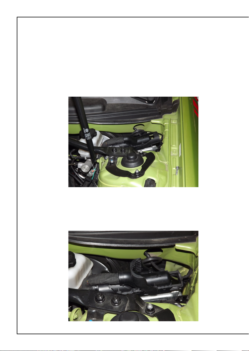
•Install ECU into vehicle as described previously
•With the ignition switch turned on, connect to the ECU via
Haltech ECU Manager Software using the USB cable provided
•Navigate to the Main Setup page by pressing F4 or by using the
Setup / Main Setup Tabs
•Go to the Advanced setup page via selecting the icon on the left of the
main setup page
•Select Electronic Throttle Tab to display the Haltech Electronic Throttle
Calibration wizard, we are now ready to calibrate the throttle.
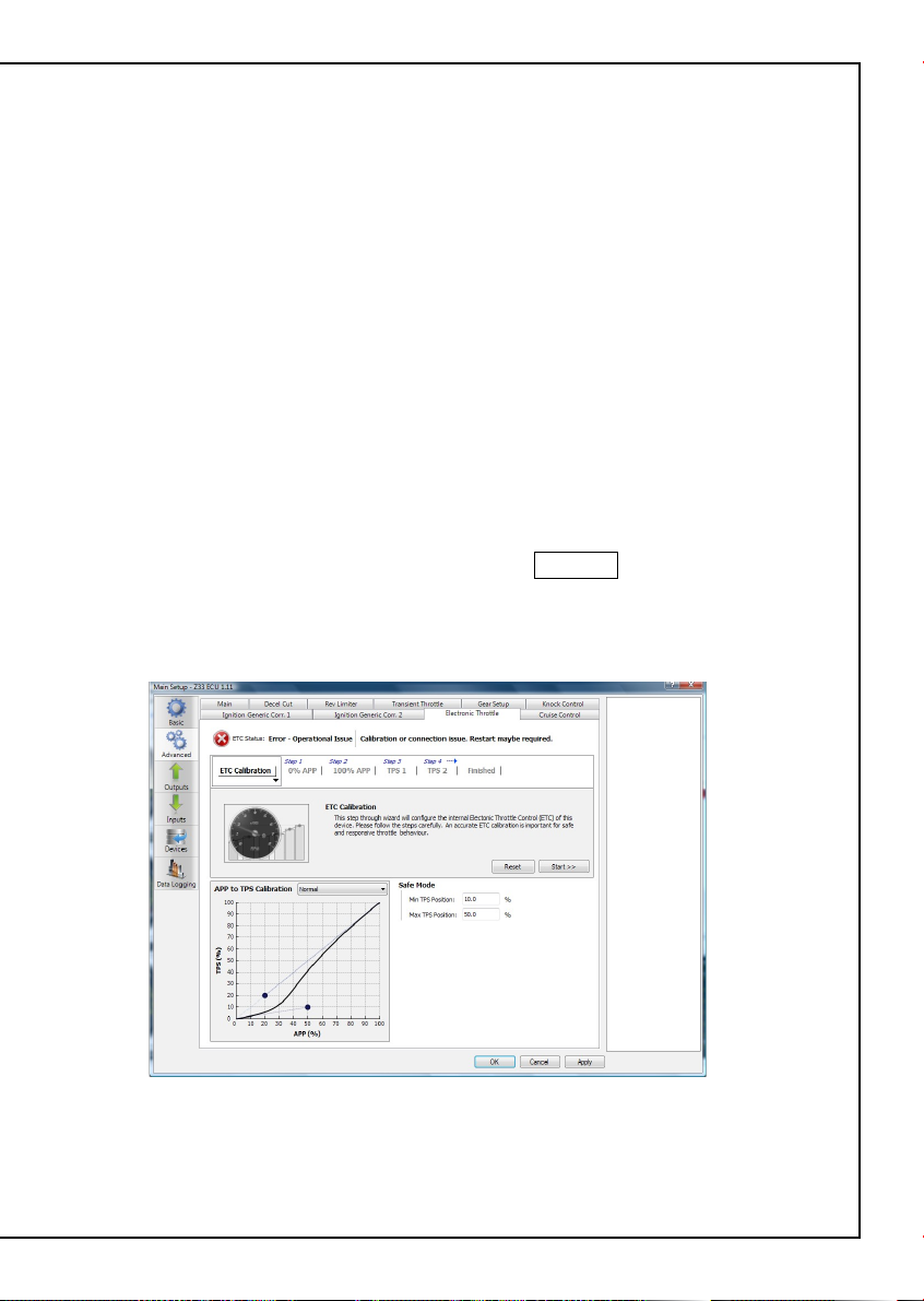
To begin the calibration process select the Start >> button
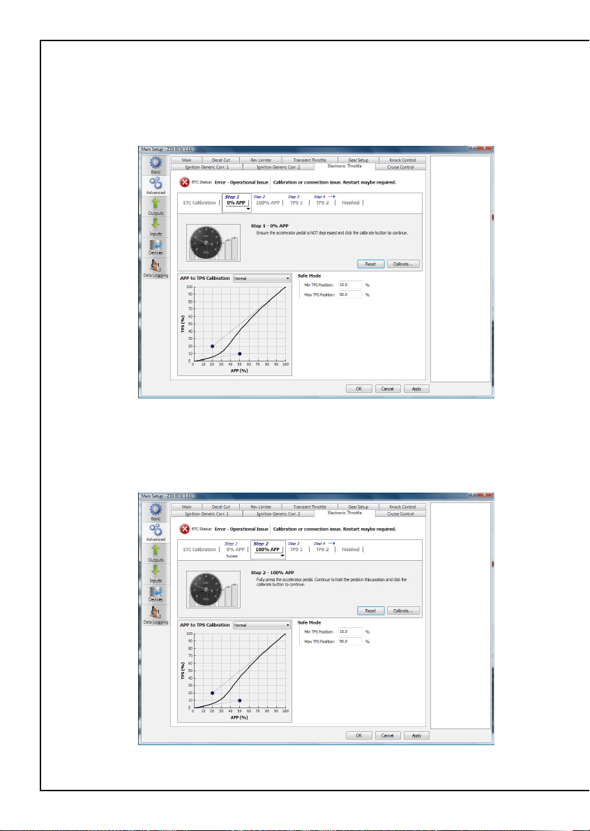
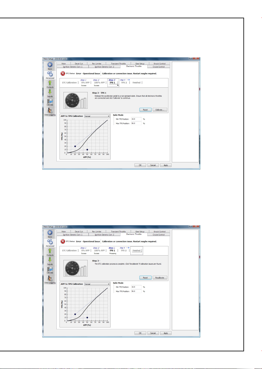
•The Haltech Calibration wizard will now guide you though the Electronic
Throttle Calibration.
igure 7- Main Setup Page showing Advanced Menu ETC Calibration Wizard