18 19
NEXUS R3 WIRING
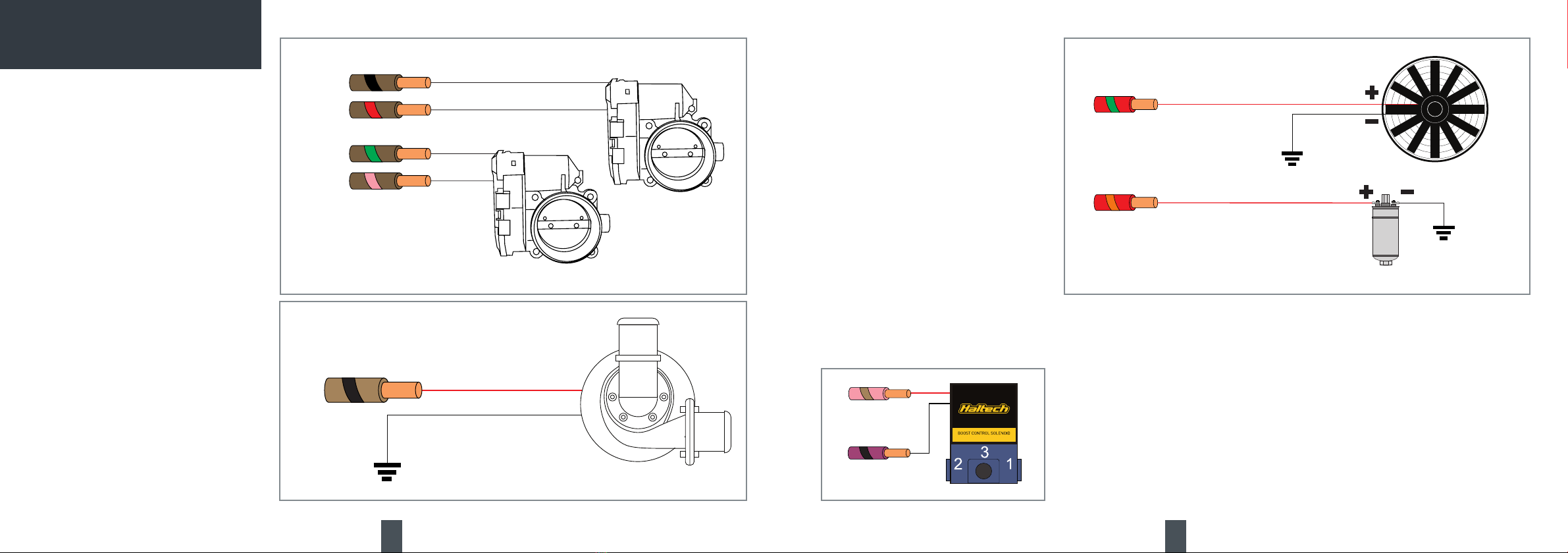
25A-HCO3
25A-HCO4
THERMOFAN
FUEL PUMP
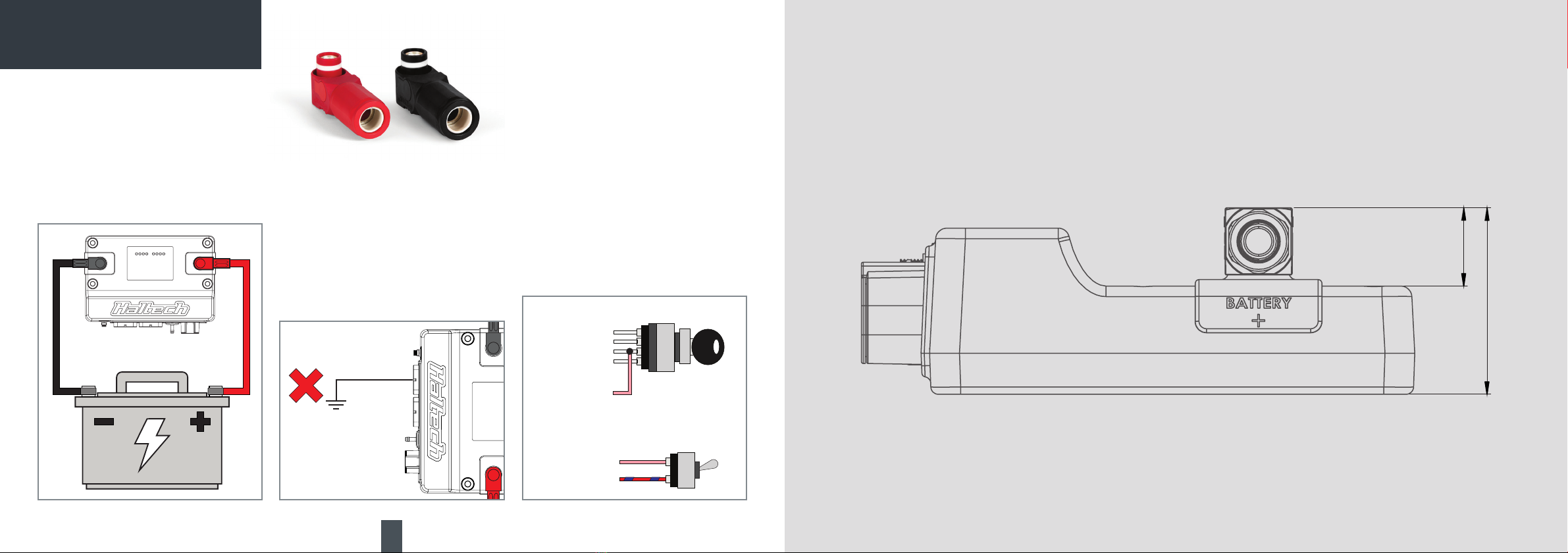
BATTERY
GROUND
BATTERY
GROUND
Example Wiring Connections
Half Bridge Outputs (HBO)
Half Bridge Outputs are push-pull Pulse Width
Modulated (PWM) outputs that can be used to
control DBW throttle motors, idle air stepper
motors or electronic wastegates.
If not being used as push-pull drivers, Half Bridge
Outputs on the NEXUS R3 can also be used as
generic high side or low side outputs capable of
driving 8A to 12V, or sinking 8A to ground.
When used for DBW throttle motors, any HBO pair
can be arbitrarily used and assigned (e.g. HBO 1
and HBO 4) in the DBW wiring settings in the NSP
software.
Specs:
• Number of channels: 6
• 8A to 12V (high), or 8A to ground (low) output
• 5A max when used as push-pull PWM (eg DBW)
• Automatic overcurrent and overtemperature
protection
• 0 to 27V feedback
• High side current feedback
• 18kHz switching speed in DBW mode
Unused HBOs can be used as:
• Generic push/pull 2.2kHz PWM output
DPO
BOOST
CONTROL
SOLENOID
BOOST
CONTROL
SOLENOID
+12V (HBO6)
BOOST SOLENOID
Example Wiring Connection
25A High Current Outputs
The NEXUS R3 features four high/low outputs
capable of sinking 25A to ground and driving 25A
to 12V. Each output has a programmable fuse
current, slow-start current and duration. Once the
electronic fuse blows the output turns off for a pre-
programmed delay duration before reactivating
the output. You can use the NSP software to define
the maximum number of retries before the output
is deactivated until the next VCU reboot. The VCU
LEDs conveniently display the output state.
25A HCOs are PWM capable and can be used
for ignition power and injector power as well
as to PWM thermofans and fuel pumps, control
HBO1
HBO4
HBO2
HBO3
DBWTHROTTLE2
DBWTHROTTLE1
The NEXUS R3 supports up to two DBW
throttles, independently controlled in
closed loop. Any pair of HBOs can be
assigned in NSP to control each throttle
motor.
Example Wiring Connections Digital Pulsed Outputs (DPO)
Digital Pulsed Outputs are capable of producing
pulsed waveforms with varying duty, varying
frequency, or switched states. When a DPO is
activated by the VCU the output will switch to
ground.
DPOs can be used to control various low-current
devices such as shift lights, bypass air control
valves, boost control solenoids, tachometers etc.
Specs:
• Number of channels: 6
• Selectable 4k7 pullup to 12V, to 5V, or disable.
• Overcurrent, overheat, and flyback protection
• Low side drive (3A max current)
• 10kHz switching speed
• 0 to 27V feedback
Unused DPOs can be also be used as:
• Generic PWM outputs
• Low speed digital switch inputs (0-12V) with
pullup enable
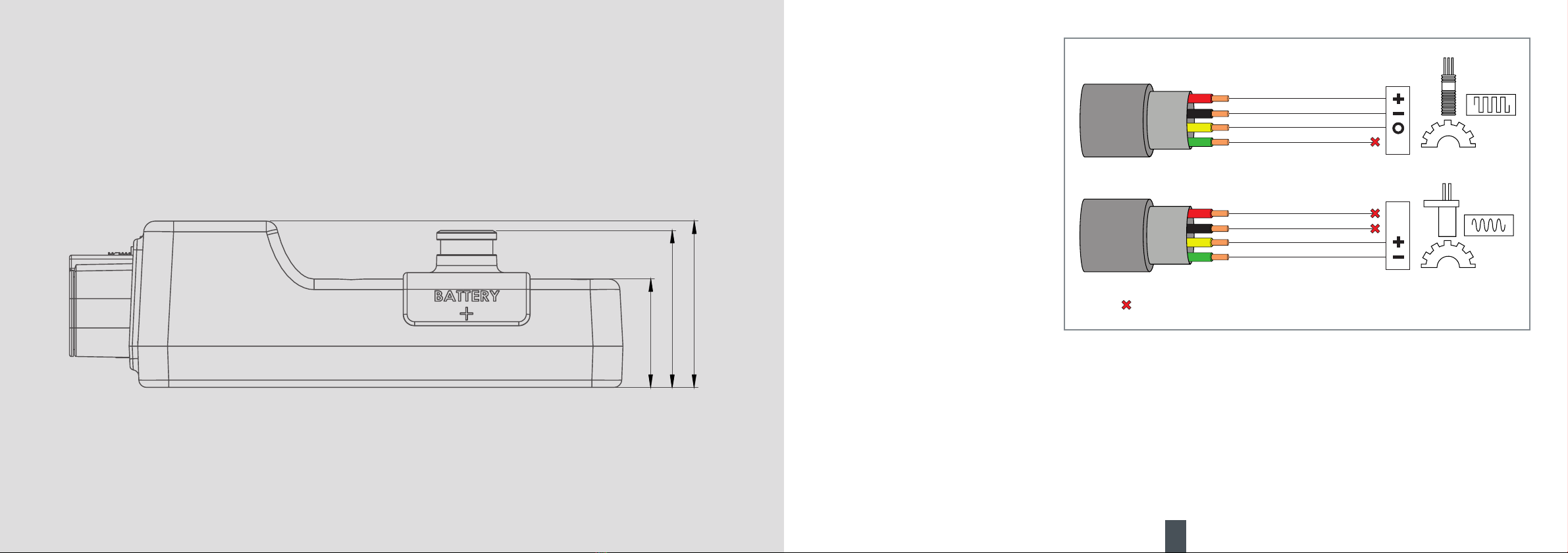
BATTERY
GROUND
HBO
ELECTRIC WATER PUMP
transbrake solenoids, nitrous solenoids etc.
Specs:
• Number of channels: 4
• 25A source or sink current output
• Automatic high and low side overcurrent
and undervoltage lockout protection
• 0 to 30V feedback
• High and low side current feedback
• 1kHz switching speed
• Capable of 0-100% duty cycle
Example Wiring Connections