Hama Ringerbox RB-10 Installation guide

00020870_71- 05.2005
00020870_71bda 18.07.2005 13:24 Uhr Seite 2

Telefon-Zusatzklingel, elektronisch
Additional Bell For Telephones, Electronical
00020870 Anthrazit
00020871 Weiss
00020870_71bda 18.07.2005 13:24 Uhr Seite 3

Die Ringerbox ist ein Tonruf-Zweitgerät
Version für Deutschland.
Inhaltsverzeichnis
1. Allgemein
2. Sicherheitshinweise
3. Lieferumfang
4. Bedienelemente
5. Kabelbetrieb
6. Wandmontage
7. Hinweise allgemein
8. Fehler-Hilfe
9. Notizen / Einstellungen
1. Allgemein
Die Ringerbox RB-10 dient als Zusatzklingel, ein sog.
Tonrufzweitgerät, am analogen Telefonanschluss.
Die Speisung erfolgt über das Telefonnetz, somit sind
keine Batterien oder externe Stromversorgungen
notwendig.
Drei Melodien stehen zur Auswahl.
Eine LED leuchtet bei Rufsignalen, auch wenn der
Lautstärke-Wahlschalter auf „OFF“ steht.
Die Bedienung erfolgt über zwei Schiebe-Schalter an
den Seiten der RB-10. Wandmontage ist möglich.
Bitte machen Sie sich mit allen Funktionen der
Ringerbox vertraut, bevor Sie diese anschließen.
Hinweis: Wenn Sie die RB-10 ausstecken wollen, so
ziehen Sie immer zuerst den TAE-N Stecker des Kabels
der RB-10 aus der TAE-Dose. Andernfalls werden
z.B. nachgeschaltete Telefone nicht mehr klingeln.
2. Sicherheitshinweise
Die Ringerbox ist nur für den Betrieb in trockenen Räu-
men zugelassen. Verwendung nur wie in dieser Bedie-
nungsanleitung beschrieben.
Die Ringerbox darf nicht modifiziert werden. Das Gerät
enthält keine Teile, die gewartet werden müssen.
Wenn das Kabel oder Gehäuse beschädigt ist, darf das
Gerät nicht mehr verwendet werden. Ebenso, wenn
Flüssigkeiten eingedrungen sind. Auch bei allen
anderen Störungen wenden Sie sich bitte an unseren
Service.
3. Lieferumfang
- Ringerbox RB-10
- Anschlusskabel mit RJ-11 und TAE-N Stecker
(Länge ca. 25 cm)
- Bedienungsanleitung
- Set Schrauben und Dübel
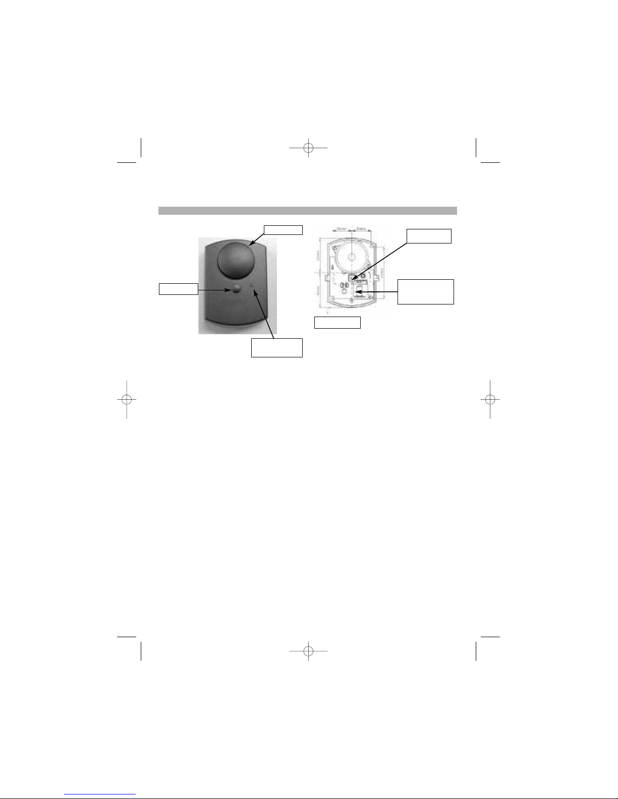
4. Bedienelemente
Wahlschalter für die Rufmelodie an der linken Seite ,
bezeichnet mit „1“, „2“ und „3“
Wahlschalter für die Lautstärke an der rechten Seite ,
bezeichnet mit „H“, „L“ und „OFF“
Schieben Sie den Melodie-Wahlschalter auf die Positi-
on „1“, „2“ oder „3“, um die von Ihnen gewünschte
Melodie einzustellen.
Schieben Sie den Lautstärke-Wahlschalter auf die
Position „L“ für leise, auf die Position „H“ für hoch,
oder „OFF“ für aus.
Bei Rufsignalen leuchtet die LED auf der Vorderseite
der RB-10 immer, auch wenn der Lautstärke-Wahl-
schalter auf Stellung „OFF“ steht!
5. Kabelbetrieb (über mitgeliefertes TAE-N-Kabel)
Stecken Sie den RJ-11 Stecker des mitgelieferten
Kabels in die RJ-11 Buchse auf der Unterseite der RB-
10, und den TAE-N Stecker in die linke Buchse Ihrer
TAE Anschlussdose. Falls die Länge des mitgelieferten
Kabels nicht ausreicht, besorgen Sie bitte im Fachhan-
del ein passendes Verlängerungskabel (4-polig, kein
Rundkabel). Dieses muss 4-polig belegt sein, andern-
falls klingeln nachgeschaltete Endgeräte nicht mehr.
6. Wandmontage
(nur durch geschulte Fachkraft durchzuführen)
Entfernen Sie die Abdeckung für die Schraube vorsich-
tig (z.B. mit einem kleinen Schraubendreher).
Lösen Sie dann die Schraube mit einem passenden
Kreuzschlitz-Schraubendreher. Die Schraube ist gegen
Herausfallen gesichert.
lBedienungsanleitung Ringerbox RB-10
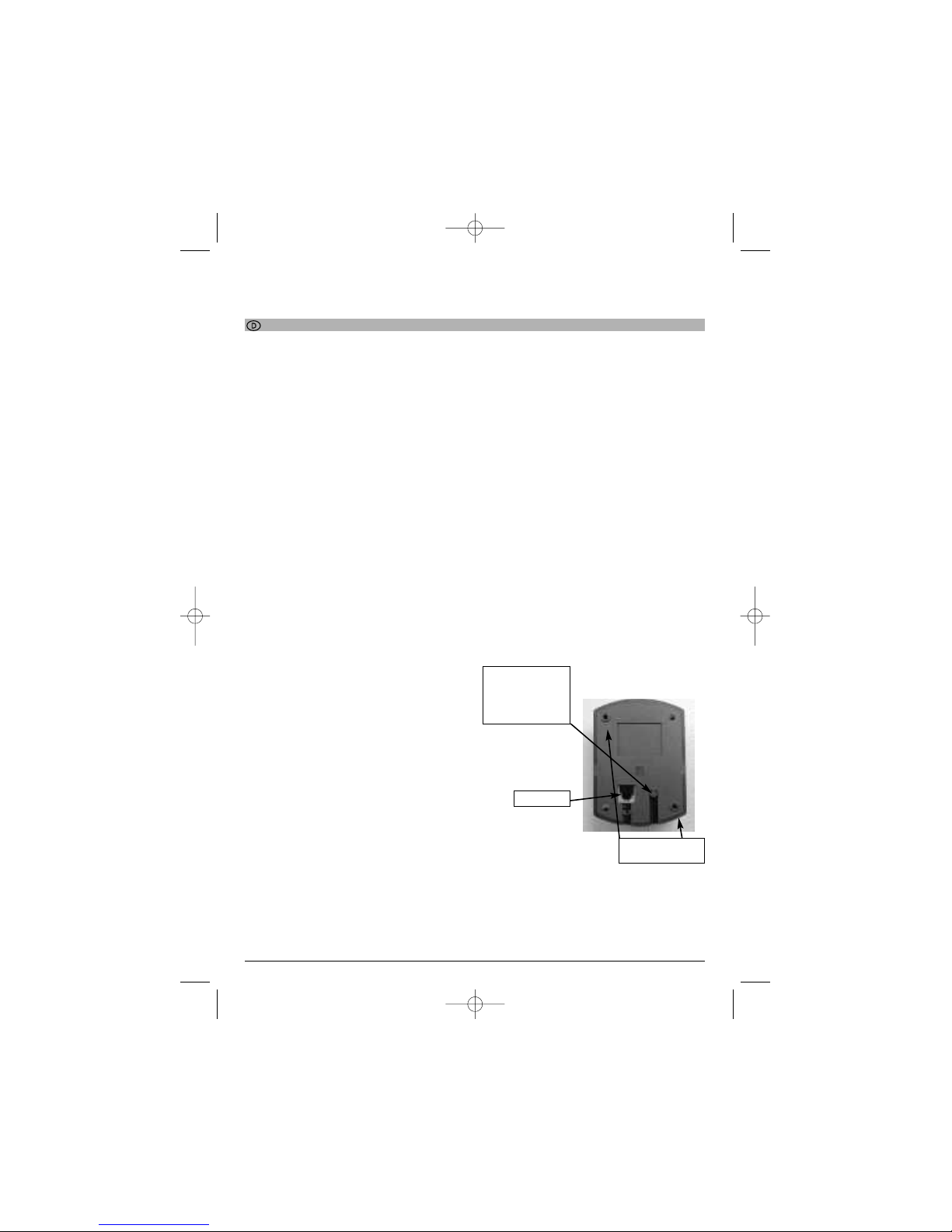
Durchführung für
alternative Anschluss-
möglichkeit an
Schraubklemmen innen
(Anschluss nur durch
geschulte Fachkräfte!)
RJ-11 Buchse
Löcher für Schrauben
zur Wandmontage
2
00020870_71bda 18.07.2005 13:24 Uhr Seite 4

Nehmen Sie anschließend vorsichtig das Oberteil ab,
indem Sie dies mit der linken Hand an den Seiten hal-
ten und das Innenteil mit der anderen Hand durch vor-
sichtiges Drücken auf die Schalter herausschieben.
Anschluss mit mitgeliefertem Kabel:
Stecken Sie den RJ-11 Stecker des mitgelieferten
Kabels in die RJ-11 Buchse auf der Unterseite der
RB-10 und verlegen Sie das Kabel sorgfältig in der
Kabelführung der RB-10. Nun stecken Sie den TAE-N
Stecker in die linke Buchse Ihrer TAE Anschlussdose.
Anschluss an Schraubklemmen:
Brechen Sie die Abdeckung der Durchführung mit
einem geeigneten Werkzeug, falls erforderlich,
vorsichtig heraus. Nun können Sie das Kabel in das
Gehäuseinnere hineinführen und an den beiden
Schraubklemmen (siehe Bild Innenansicht) anklemmen.
WICHTIG: Nachdem die Abdeckung heraus gebrochen
wurde, darf die RB-10 nur noch für Wandmontage
eingesetzt werden.
Achten Sie darauf, dass an den Bohrstellen keine
Leitungen in der Wand verlaufen!
Bohren Sie mit Hilfe der mitgelieferten Bohrschablone
die Löcher an der gewünschten Stelle in die Wand.
Befestigen Sie nun die RB-10 mit den mitgelieferten
Dübeln und Schrauben an der Wand.
Drehen Sie die Schrauben dabei vorsichtig fest, damit
das Gehäuse der RB-10 nicht beschädigt wird.
Drücken Sie nun wieder vorsichtig das Oberteil auf die
RB-10. Beachten Sie, dass die LED nicht beschädigt
oder gedrückt wird. Drehen Sie die Schraube und
setzen Sie die Abdeckung für die Schraube wieder ein.
7. Hinweise allgemein
Dieses Produkt entspricht den Richtlinien der R&TTE
und trägt das CE-Zeichen.
Gewährleistung im Rahmen der gesetzlichen Regelung.
Das Gerät darf nicht modifiziert oder mechanisch
beschädigt sein. Die Ringerbox RB-10 darf nur für den
beschriebenen Zweck benutzt werden.
Die Ringerbox kann auch an die analogen Ausgänge
einer ISDN-Tk-Anlage angeschlossen werden.
Für Rundkabel sind die Kabelführungen der Ringerbox
RB-10 nicht vorgesehen. Verwenden Sie ausschließlich
flache Kabel. Ggf. können Sie jedoch die kleine Rast
Nase des RJ-11 Steckers mit einer geeigneten Zange
ein Stück kürzer zwicken.
Bitte lesen Sie diese Bedienanleitung genau durch.
Produktunterstützung erhalten Sie von unserem techni-
schen Service.
8. Fehler-Hilfe
Problem:
Mein Telefon oder Fax klingelt nicht
Lösung:
Überprüfen Sie den festen Sitz des Kabels an der
Ringerbox.
Wenn das Kabel an der TAE-Dose eingesteckt ist, muss
das Kabel auch an der Ringerbox angesteckt sein,
ansonsten klingeln nachgeschaltete Endgeräte nicht!
Das Kabel muss an der RB-10 hörbar einrasten.
Das TAE-Kabel zur Ringerbox muss 4-polig sein.
© Böhm-Elektronik 2004 Stand: 07-2004 V1.0
Irrtum und Änderungen vorbehalten
Abdeckung für
die Schraube
LED
Leuchtet bei Rufsignalen
Schallaustritt
Bild: Innenansicht
Schraubklemmen
Abdeckung der Durch-
führung, kann heraus
gebrochen werden,
falls erforderlich
3
00020870_71bda 18.07.2005 13:24 Uhr Seite 5

The Ringerbox is an auxiliary ringer Version for Germany.
Table of Contents
1. General Information
2. Safety Instructions
3. In the Box
4. Controls
5. Cable operation
6. Wall mounting
7. General Notes
8. Troubleshooting
9. Notes/Settings
1. General Information
The RB-10 Ringerbox acts as a second telephone bell,
a so-called auxiliary ringer, for an analog telephone
connection.
Power is supplied via the telephone network which
means that no batteries or external power units are
required.
Three tunes are available.
An LED lights when a ring signal is received, even if the
volume selection switch is set to “OFF”.
The unit is operated via two sliding switches at the
sides of the RB-10. It can also be wall-mounted.
Make sure to familiarise yourself with all functions of
the Ringerbox before connecting it.
Note:When disconnecting the RB-10, first remove the
TAE-N connector of the RB-10 cable from the TAE
socket. Otherwise telephones etc. connected in series
will not ring.
2. Safety Instructions
The Ringerbox is intended for use in dry areas only.
Only use it as described in this manual.
The Ringerbox may not be modified. The unit switch
does not contain any parts that need servicing.
Do not use the unit if the cable or casing is damaged
or if liquid enters the Ringerbox. Contact Hama service
for all other errors.
3. In the Box
- Ringerbox RB-10
- Connecting cable with RJ-11 and TAE-N connectors
(length approx. 25cm)
- Operating Instructions
- Set of screws and rawl plugs
4. Controls
Selection switch for the ring tune on the left, marked
“1”, “2” and “3”.
Selection switch for the volume on the right, marked
“H”, “L” and “OFF”.
Slide the tune selection switch to position “1", “2” or
“3” to select the tune of your choice.
Slide the volume selection switch to position “L” for
low, to position “H” for high or to “OFF” to deactivate
the ring tune.
The LED on the front of the RB-10 always lights when a
ring signal is received, even if the volume selection
switch is set to “OFF”!
5. Cable operation (via supplied TAE-N cable)
Insert the RJ-11 connector of the supplied cable into
the RJ-11 terminal on the base of the RB-10 and the
TAE-N connector into the left terminal of your TAE
connection socket. If the supplied cable is not long
enough, purchase a corresponding extension cable (4-
pin, the cable may not be round). It must be 4-pin,
otherwise terminal devices connected in series after it
will not ring.
6. Wall mounting (by qualified technicians only)
Carefully remove the screw cover
(e.g. with a small screwdriver). Loosen the screw using
an appropriate Philips screwdriver. The screw is
secured to prevent it falling out.
Then remove the upper section carefully, by holding the
sides with your left hand and pressing the inner section
out by pushing the switch.
Leadthrough for alter-
native connection opti-
on to internal screw
terminals (may only be
connected by qualified
technicians!)
RJ-11 terminal
Holes for wall-
mounting screws
4
LUser Manual Ringerbox RB-10
00020870_71bda 18.07.2005 13:24 Uhr Seite 6

Connection using the cable supplied:
Insert the RJ-11 connector of the supplied cable into
the RJ-11 terminal on the base of the RB-10 and lay the
cable carefully in the cable guide of the RB-10. Now
insert the TAE-N connector into the left terminal of your
TAE connection socket.
Connection to screw clamps:
Remove the cover of the cable leadthrough carefully
using a suitable tool if necessary. You can now route
the cable into the interior of the casing and connect it
to the two screw terminals (see internal view).
IMPORTANT: After the cover has been broken, the RB-
10 can only be used for wall mounting.
Ensure that there are no wires in the wall where the
holes are to be drilled!
Using the drilling template, drill the holes at the requi-
red position on the wall. Now attach the RB-10 to the
wall using the rawl plugs and screws provided.
Tighten the screws carefully to prevent damage to the
casing of the RB-10.
Now press the upper section carefully onto the RB-10.
Ensure that the LED is not damaged and that no
pressure is exerted on it. Tighten the screw and insert
the cover for the screw again.
7. General Notes
This product complies with R&TTE Directives and is
CE-certified.
A warranty is provided as required by law. The unit
must not be opened, modified or damaged by
mechanical means. The RB-10 Ringerbox switch may
only be used for the purpose described here.
The Ringerbox can also be connected to the analog
outputs of an ISDN system.
The cable guides of the RB-10 Ringerbox are not desi-
gned for round cables. Use flat cables only. If neces-
sary, you can shorten the small locking lug of the RJ-11
connector using a suitable pliers.
Please read this manual carefully.
Contact our technical service for support.
8. Troubleshooting
Problem:
My telephone or fax does not ring.
Solution:
Ensure that the cable is securely connected to the
Ringerbox.
If the cable is connected to the TAE socket, the cable
must also be connected to the Ringerbox, otherwise
terminal devices connected in series do not ring!
The cable must audibly click into position on the RB-10.
The TAE cable to the Ringerbox must be 4-pin.
© Böhm-Elektronik 2004 Date: 06-2004 V1.0 Errors excepted;
subject to changes
Screw cover
LED
Lights on ring signal
Sound outlet
Fig. Internal view
Screw terminals
Leadthrough cover,
can be removed if
necessary
5
00020870_71bda 18.07.2005 13:24 Uhr Seite 7

Konformitätserklärung gemäß dem Gesetz über Funkanlagen und
Telekommunikationsendeinrichtungen (FTEG) und der Richtlinie 1999/5/EG (R&TTE)
Declaration of Conformity in accordance with the Radio and Telecommunications Terminal Equipment Act
(FTEG)
and Directive 1999/5/EC (R&TTE Directive)
Hersteller/Verantwortliche Person // The manufacturer / responsible person
erklärt, dass das Produkt
declares that the product
Type (ggf. Anlagenkonfiguration mit Angabe der Module):
Type (if applicable, configuration including the modules)
❑Telekommunikations(TK-)endeinrichtung ❑Funkanlage
Telecommunications terminal equipment Radio equipment
Verwendungszweck Geräteklasse
Intended purpose Equipment class
bei bestimmungsgemäßer Verwendung den grundlegenden Anforderungen des § 3 und
den übrigen einschlägigen Bestimmungen des FTEG (Artikel 3 der R&TTE) entspricht.
complies with the essential requirements of § 3 and the other relevant provisions of the FTEG (Article 3 of the
R&TTE Directive), when used for its intended purpose.
Gesundheit und Sicherheit gemäß § 3 (1) 1. (Artikel 3 (1) a))
Health an safety requirements pursuant to § 3 (1) 1. (Article 3(1) a))
angewendete harmonisierte Normen ... Einhaltung der grundlegenden
Anforderungen auf andere Art und Weise
(hierzu verwendete Standards/
Spezifikationen) ...
Other means of proving conformity with the essential
requirements (standards/specifications used) ...
Schutzanforderungen in Bezug auf die elektromagnetische Verträglichkeit § 3 (1) 2,
Artikel 3 (1) b))
Protection requirements concerning electromagnetic compatibility § 3(1)(2). (Article 3(1)(b))
angewendete harmonisierte Normen ... Einhaltung der grundlegenden
Anforderungen auf andere Art und Weise
(hierzu verwendete Standards/
Spezifikationen) ...
Other means of proving conformity with the essential
requirements (standards/specifications used) ...
Harmonised standards applied ...
Hamonised standards applied ...
Hama GmbH & Co.
Telefon-Zusatzklingel RB-10
Hama Art.-Nr. 00020870 Anthrazit
00020871 Weiß
TBR 21: 1998
Telefon-Zusatzklingel RB-10
EN 60950: 1992 (inkl. Anl: 1993, A2: 1993,
A3: 1995, A4: 1996, All: 1997)
EN 55022: 1998 Grenzwertklasse B
EN 55024: 1998
lL
6
00020870_71bda 18.07.2005 13:24 Uhr Seite 8

Maßnahmen zur effizienten Nutzung des Funkfrequenzspektrums
Measures for the efficient use of the radio frequency spectrum
❑ Luftschnittstelle bei Funkanlagen gemäß § 3(2) (Artikel 3(2))
Air interface of the radio systems pursuant to § 3(2) (Article 3(2))
angewendete harmonisierte Normen ... Einhaltung der grundlegenden
Anforderungen auf andere Art und Weise
(hierzu verwendete Standards/
Schnittstellenbeschreibungen) ...
Other means of proving conformity with the essential
requirements (standards/interface specifications used) ...
EN / HN ETS
Reg TP
BAPT
Anschrift
Address
+ TK-Nr.
Phone, fax, e-mail
Ort, Datum
Place & date of issue
Harmonised standards applied ...
Monheim, 18.07.05
Tel: 09091/502-274
Fax: 09091/502-0
e-mail: [email protected]
http://www.hama.de
Hama GmbH & Co.
Dresdner Straße 9
86651 Monheim
e
7
00020870_71bda 18.07.2005 13:24 Uhr Seite 9
Table of contents
Languages:
Other Hama Telephone Accessories manuals

Hama
Hama CallBlocker User manual

Hama
Hama DISPLEX EASY-ON 195524 User manual

Hama
Hama Magnet User manual

Hama
Hama 00201518 User manual

Hama
Hama Magnet User manual

Hama
Hama 40616 User manual

Hama
Hama 00177798 User manual

Hama
Hama Gravity Pro User manual

Hama
Hama Bike User manual

Hama
Hama Universal User manual
Popular Telephone Accessories manuals by other brands

Texecom
Texecom Speech Dailler Operator's manual

Panasonic
Panasonic KX-TVA200 user guide

Panasonic
Panasonic Easa-Phone VA-123210 Installation and programming manual

Plantronics
Plantronics VOYAGER CS60 Guide

Aristel
Aristel AV256 installation guide

Elenco Electronics
Elenco Electronics K-35 Assembly and instruction manual