Anwendung
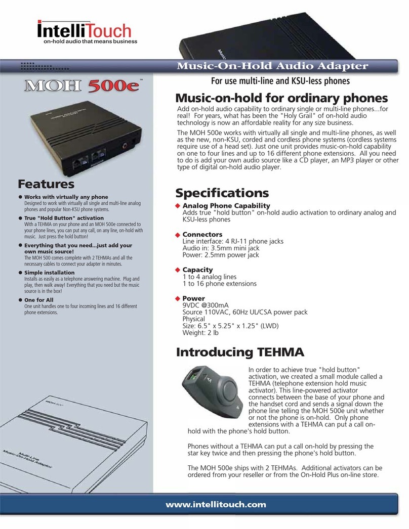
Multifunktions-Modul MFM/TI 611-0
zur Anreihung an das Systemtelefon
ISDN TI 611-0. Ausgestattet mit 10
Funktionstasten.
Funktionen:
Rufnummern mit max. 22 Stellen,
Steuerbefehle wie Rufumleitung
und/oder Abschaltung, Nachtschal-
tung etc., Schalt- und Steuerbefehle
im Rahmen der Türtelefonie. An ein
TI 611-0 kann max. 1 MFM/TI 611-0
rechts angereiht werden. Für Wand-,
Tisch- und UP-Montage geeignet.
Montage
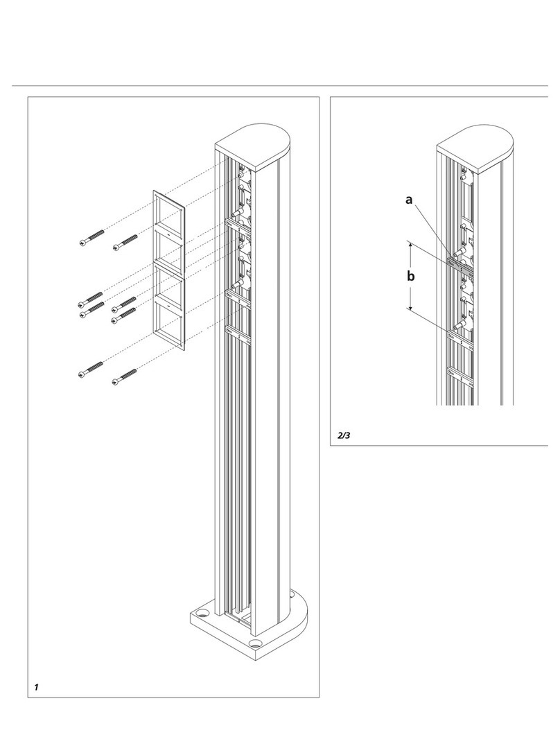
1Systemtelefon und Multifunk-
tions-Modul wie dargestellt öffnen.
2(ohne Abbildung)
Schwachstrom-Verbindungsstecker
am Systemtelefon abziehen
3Vorgeprägte Verbindungsstege
"a" im Systemtelefon und Multi-
funktions-Modul ausbrechen und
Unterteile mit den dem Multifunk-
tions-Modul beiliegenden 2 Verbin-
dungselementen verschrauben.
4(ohne Abbildung)
Anschlussdrähte durch die Kabelein-
führung des Gehäuse-Unterteils des
Systemtelefones einziehen und die
Kombination der Unterteile AP- oder
UP befestigen. Siehe Produktinfor-
mationen TI 611-0 bzw. ZUR 611-...
Bei Tischmontage siehe Produktin-
formationen ZT/TI 611- 0 und
ZMF 611-10
5(ohne Abbildung)
Systemtelefon ISDN TI 611-10 nach
entsprechendem Außenschaltplan
anschließen.
6(ohne Abbildung)
Flachbandkabel (gesteckt am
Stecker Tel./MFM) des Multifunk-
tions-Modules MFM/TI 611-0 auf
der linken Seite der Telefonleiter-
platte am Stecker "MFM" stecken.
7(ohne Abbildung)
Schwachstrom-Verbindungsstecker
des Systemtelefon Unterteils auf der
Telefonleiterplatte stecken.
8(ohne Abbildung)
Flachbandkabel des Multifunktions-
Modules zusammenlegen und
Gehäuseteile verschließen.
Application
Multifunction module MFM/TI 611-0
for in-row mounting with system
telephone ISDN TI 611-0. Equipped
with 10 function buttons.
Functions:
Call numbers with max. 22 digits
Switching and control commands
such as call forwarding or silencing,
night service etc. within scope of
entryway telephony. A maximum of
1 MFM/TI 611-0 can be mounted
right in-row with a TI 611-0. For
wall, table-top and flush mount
installation.
Mounting
1Open system telephone and multi-
function module as per drawing.
2(not shown)
Remove low-voltage plug in the
System telephone
3Remove knockout "a" in the bot-
tom half of System telephone and
multifunction module and use the 2
connecting elements supplied with
the multifunction module to bolt
the lower halves.
4(not shown)
Pull the connecting leads through
the Gable knockout in the lower
halves of the housing and fasten the
combination of the lower halves
wall mounting or flush mounting
See product information TI 611-0 or
ZUR 611-....; product information
ZT/TI 611 -0 and ZMF 611-10 for
table top mounting.
5(not shown)
Connection of system telephone
TI 611-0 as per corresponding
wiring diagram.
6(not shown)
Connect the cable (connected in the
plug Tel./MFM) of the multifunction
module MFM/TI 611-0 in the plug
"MFM" an the left side of the tele-
phone pcb.
7(not shown)
Connect the low-voltage plug of the
lower half of the telephone
housing with the telephone pcb
8(not shown)
Fold up the cable of the multifunc-
tion module and close the housing
halves.
Deutsch
Montage
English
Mounting
9Öffnen des Beschriftungsfeldes.
10 (ohne Abbildung)
Programmierung der Tasten siehe
Bedienungsanleitung TI 611-0.
(Makroprogrammierung)

