Subject to change without notice
10
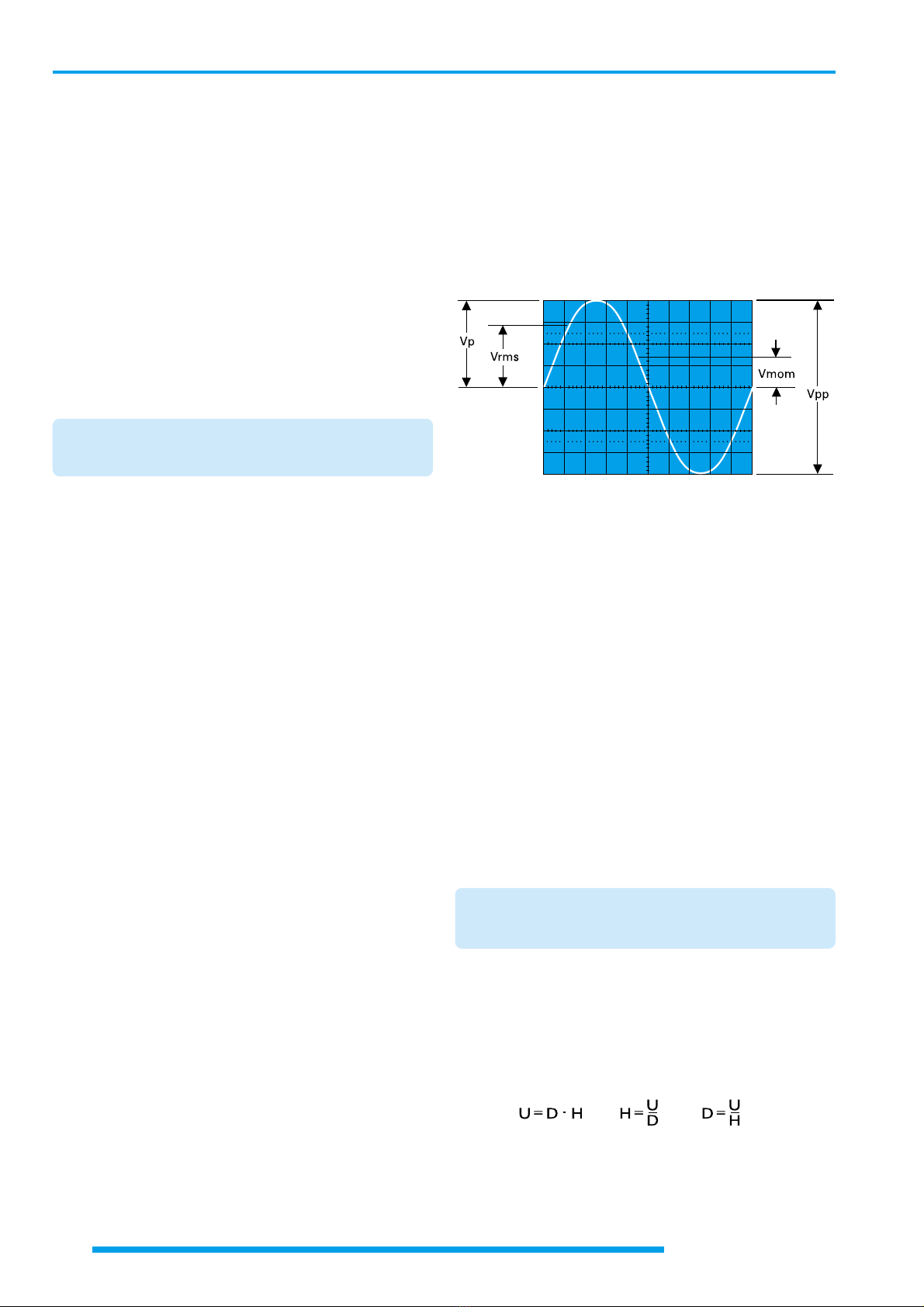
Type of signal voltage
set time coefficient Tc = 0.2s/div,
required wavelength L = 1:0.2 = 5div.
Displayed ripple wavelength L = 1div,
set time coefficient Tc = 10ms/div,
required ripple freq. F = 1:(1x10x10-3) = 100Hz.
TV-Line frequency F = 15625Hz,
set time coefficient Tc = 10µs/div,
required wavelength L = 1:(15 625x10-5) = 6.4div.
Sine wavelength L = min. 4div, max. 10div,
Frequency F = 1kHz,
max. time coefficient Tc = 1:(4x10³) = 0.25ms/div,
min. time coefficient Tc = 1:(10x103) = 0.1ms/div,
set time coefficient Tc = 0.2ms/div,
required wavelength L = 1:(103x0.2x10-3) = 5div.
Displayed wavelength L = 0.8div,
set time coefficient Tc = 0.5µs/div,
pressed X-MAG. (x10) button: Tc = 0.05µs/div,
required rec. freq. F = 1:(0.8x0.05x10-6) = 25MHz,
required period T = 1:(25x106) = 40ns.
If the time is relatively short as compared with the complete
signal period, an expanded time scale should always be applied
(X-MAG. (x10) active). In this case, the time interval of interest
can be shifted to the screen center using the X-POS. control.
When investigating pulse or square waveforms, the critical
feature is the risetime of the voltage step. To ensure that
transients, ramp-offs, and bandwidth limits do not unduly
influence the measuring accuracy, the risetime is generally
measured between 10% and 90% of the vertical pulse height.
For measurement, adjust the Y deflection coefficient using its
variable function (uncalibrated) together with the Y-POS.
control so that the pulse height is precisely aligned with the
0% and 100% lines of the internal graticule. The 10% and
90% points of the signal will now coincide with the 10% and
90% graticule lines. The risetime is given by the product of the
horizontal distance in div between these two coincident
points and the calibrated time coefficient setting. The fall time
of a pulse can also be measured by using this method.
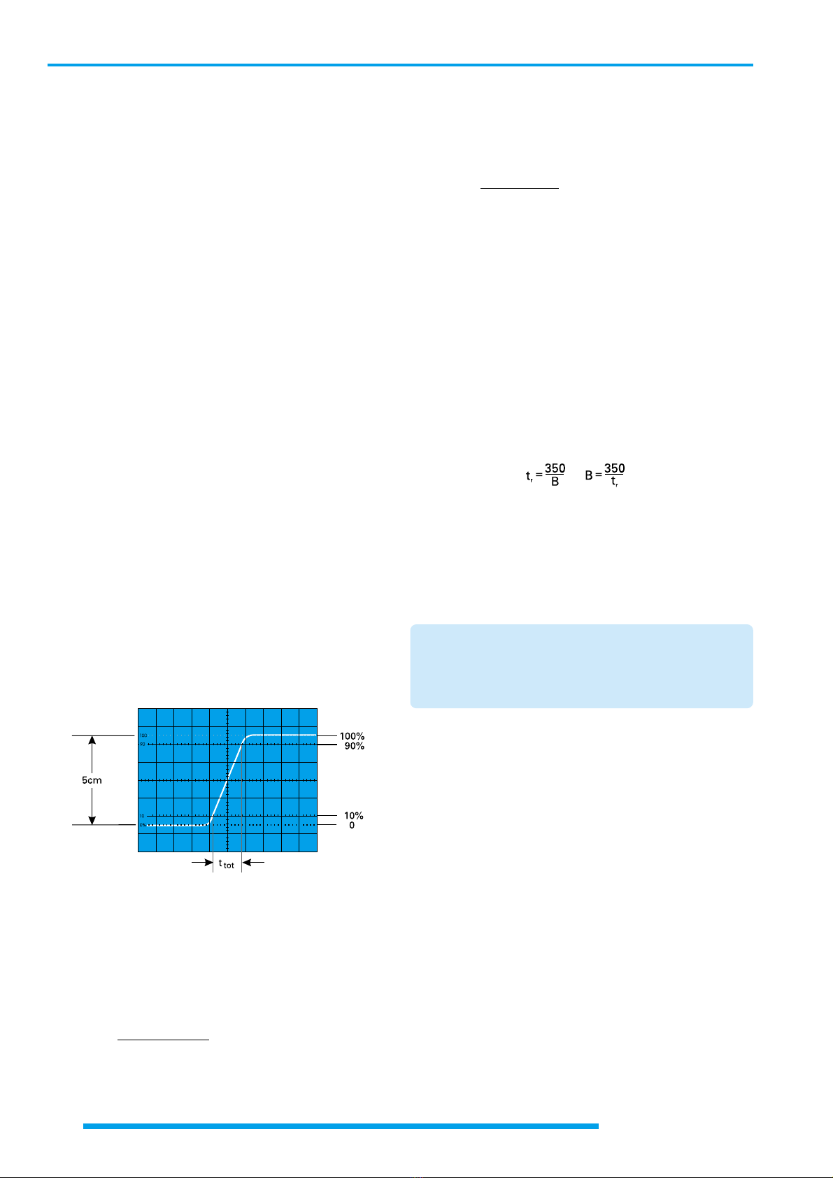
The following figure shows correct positioning of the oscillo-
scope trace for accurate risetime measurement.
With a time coefficient of 5ns/div (X x10 magnification active),
the example shown in the above figure results in a total
measured risetime of
ttot = 1.6div x 5ns/div = 8ns
When very fast risetimes are being measured, the risetimes
of the oscilloscope amplifier and of the attenuator probe has
to be deducted from the measured time value. The risetime
of the signal can be calculated using the following formula.
tr= √ttot2- tosc2- tp2
In this ttot is the total measured risetime, tosc is the risetime
of the oscilloscope amplifier (HM1004-3 approx. 3.5ns) and tp
the risetime of the probe (e.g. = 2ns). If ttot is greater than
34ns, then ttot can be taken as the risetime of the pulse, and
calculation is unnecessary.
Calculation of the example in the figure above results in a
signal risetime
tr= √82- 3,52- 22 = 6,9ns
The measurement of the rise or fall time is not limited to the
trace dimensions shown in the above diagram. It is only
particularly simple in this way. In principle it is possible to
measure in any display position and at any signal amplitude.
It is only important that the full height of the signal edge of
interest is visible in its full length at not too great steepness
and that the horizontal distance at 10% and 90% of the
amplitude is measured. If the edge shows rounding or over-
shooting, the 100% should not be related to the peak values
but to the mean pulse heights. Breaks or peaks (glitches) next
to the edge are also not taken into account. With very severe
transient distortions, the rise and fall time measurement has
little meaning. For amplifiers with approximately constant
group delay (therefore good pulse transmission performance)
the following numerical relationship between rise time tr(in
ns) and bandwidth B (in MHz) applies:
Connection of Test Signal
In most cases briefly depressing the AUTO SET causes a
useful signal related instrument setting. The following expla-
nations refer to special applications and/or signals, demand-
ing a manual instrument setting. The description of the
controls is explained in the section “controlsand readout”.
Caution:
When connecting unknown signals to the oscilloscope
input, always use automatic triggering and set the
input coupling switch to AC (readout). The attenuator
should initially be set to 20V/div.
Sometimes the trace will disappear after an input signal has
been applied. Then a higher deflection coefficient (lower input
sensitivity) must be chosen until the vertical signal height is
only 3-8div. With a signal amplitude greater than 160Vpp and
the deflection coefficient (VOLTS/DIV.) in calibrated condi-
tion, an attenuator probe must be inserted before the vertical
input. If, after applying the signal, the trace is nearly blanked,
the period of the signal is probably substantially longer than
the set time deflection coefficient (TIME/DIV.). It should be
switched to an adequately larger time coefficient.
The signal to be displayed can be connected directly to the Y-
input of the oscilloscope with a shielded test cable such as
HZ32 or HZ34, or reduced through a x10 or x100 attenuator
probe. The use of test cables with high impedance circuits is
only recommended for relatively low frequencies (up to
approx. 50kHz). For higher frequencies, the signal source
must be of low impedance, i.e. matched to the characteristic
resistance of the cable (as a rule 50Ω). Especially when
transmitting square and pulse signals, a resistor equal to the
characteristic impedance of the cable must also be connected
across the cable directly at the Y-input of the oscilloscope.
When using a 50Ωcable such as the HZ34, a 50Ωthrough
termination type HZ22 is available from HAMEG. When
transmitting square signals with short rise times, transient
phenomena on the edges and top of the signal may become