manuals.online logo
Brands
  1. Home
  2. •
  3. Brands
  4. •
  5. YOKOGAWA
  6. •
  7. Test Equipment
  8. •
  9. YOKOGAWA MY40 User manual

YOKOGAWA MY40 User manual

User's
Manual
Store this manual in an easily accessible place
for quick reference. B3
Printed in China
Model and Sufx Code
MY40 Insulation Resistance Tester
 Rating -01 125 V/200 MΩ, 250 V/200 MΩ, 500 V/2000 MΩ, 1000 V/2000 MΩ
MODEL SUFFIX Specifications
1. Safety Precautions
This product is designed to be used by a person with specialized knowledge.
When operating the instrument, be sure to observe the cautionary notes given below to ensure correct and
safe use of the instrument. If you use the instrument in any way other than as instructed in this manual,
the instrument's protective measures may be impaired.
This manual is an essential part of the product; keep it a safe place for future reference.
YOKOGAWA is by no means liable for any damage resulting from use of the instrument in contradiction to
these cautionary notes.
The following safety symbols are used on the instrument and in this manual.
This symbol indicates that the operator must refer to an explanation in the user’s manual
in order to avoid risk of injury or death of personnel or damage to the tester.
WARNING
Indicates a hazard that may result in the loss of life or serious injury of the user unless
the described instruction is abided by.
CAUTION
Indicates a hazard that may result in an injury to the user and/or physical damage to
the product or other equipment unless the described instruction is abided by.
NOTE
Indicates information that is essential for handling the instrument or should be noted in order to
familiarize yourself with the instrument’s operating procedures and/or functions.
High-voltage Terminal
This symbol indicates a dangerous voltage level (terminals with voltagesexceeding
1000 volts must be so marked). Never touch the terminals.
AC Voltage
This symbol indicates the presence of an AC voltage.
Double Insulation
This symbol indicates double insulation.
■ Always observe the following instructions. Failure to do so may result in electric shock or
other dangers that may lead to serious injury or the loss of life.
WARNING
This instrument is a insulation resistance tester that can measure insulation resistance (AC voltage).
Do not use this instrument for other purpose.
Do not use the instrument if there is a problem with its physical appearance.
1. During Measurement of Insulation Resistance
• A high voltage is present at the probes. Do not touch the measured object or the earth or line terminal.
2. Immediately After Measurement of Insulation Resistance
• The probes or the measured object may remain highly charged.
Do not touch them immediately after the completion of measurement.
3. During Measurement of AC Voltages
• Do not press the MEAS key while measuring AC voltages.
• Voltage that exceeds the specied limit must not be applied to terminals.
4. Probes
• Use the probes supplied by Yokogawa with this tester.
• Do not use probes that have deteriorated or are defective.
• Remove the probes from the measured object before attaching/detaching the probes to/from the tester.
5. Insulation of Casing
• A puncture in the protective insulation may occur if there are any cracks or other damage in
the casing as a result of the instrument having been dropped or knocked against another object.
Do not use the instrument before taking the necessary remedial measures; ask the manufacturer to repair it.
6. The Measured Object
• Turn off the power to the measured object before you begin measuring insulation resistance.
• Avoid touching any electried parts while using the tester in a location with live electricity.
Safety protectors such as rubber-insulated gloves should be worn to prevent electrical shock
when using the tester.
7. Operating Environment
• Do not operate the tester in an atmosphere where any ammable or explosive gas is present.
• Do not use the tester if there is condensation on it.
8. Do Not Remove the Casing or Disassemble
Do not open the case except when replacing batteries.
Only qualied YOKOGAWA personnel may remove the case and disassemble or alter the instrument.
Do not attempt to repair/modify the instrument yourself, as doing so is extremely dangerous.
CAUTION
• The instrument is for domestic use (Class B) and meets the electromagnetic compatibility requirements.
• To verify the instrument's functionality, check that the measured value is update after turning on the power.
If the measured value is not update, the reading will be incorrect and may lead to possible electrical shock
or personal injury.
■ Measurement Categories
Measurement category of the MY40
WARNING
The instrument is designed for measurement category III.
Do not use the instrument for measurements in locations falling that fall under measurement category IV.
Measurement category of the Probes
Line probe (98001) With cap: 600 V CAT III Without cap: 600 V CAT II
Earth probe (98002) 600 V CAT III
WARNING
A cap is provided on the tip of the line probe.
Use the line probe with the cap on for safety (safety standard: EN61010-031).
Measurement
category
O
(None, Other)
CAT II
CAT III
CAT IV
Circuits not connected to
a mains power source.
Appliances,
portable equipment, etc.
Distribution board,
circuit breaker, etc.
Overhead wire,
cable systems, etc.
Other circuits that are not directly connected
to MAINS.
For measurements performed on circuits
directly connected to the low-voltage installation.
For measurements performed
in the building installation.
For measurements performed
at the source of the low-voltage installation.
Description Remarks
2. Measuring Functions and Additional Features
■ Measuring Functions
• Measuring the insulation resistance (four ratings)
125 V/ 200 MΩ, 250 V/ 200 MΩ, 500 V/ 2000 MΩ, 1000 V/ 2000 MΩ
• Measuring AC voltages (sine wave at 45 to 400 Hz)
• Measuring conductor resistances (0 to 400.0 Ω)
Continuity test (beeps for 40 Ω or less)
■ Additional Features
• Memory feature (data saving)
Up to 20 measured values of the insulation resistance for each rating can be saved to memory.
• Live-line alarm
When an AC voltage of 40 V or more is applied between the input terminals,
the ALARM LED ashes and the buzzer beeps (except during AC voltage measurement).
• Comparator
When a measured insulation resistance is less than the reference value setting,
the LOW mark appears and the buzzer beeps.
• HOLD feature
Measured insulation resistances are automatically held for approximately ve seconds.
• High-voltage indication
If a DC voltage exists between the terminals, the HV mark and the ALARM LED come on.
• Discharge feature
The tester is designed to begin discharging when the MEAS key is turned off.
It indicates the discharging status with a bar graph, and the HV mark and ALARM LED come on
during discharging (andoff when discharging is complete).
• Auto-power off
The tester is automatically turned off when no key operations are performed for 10 minutes.
• LCD backlight
The backlight can be turned on/off with the LIGHT key.
• Locking the MEAS key
Pulling the MEAS key up allows for continuous measurement over a prolonged time.
• Lock for inadvertent setting of 1000-V range
This mechanism protects the measured circuit from damage due to inadvertent measurement with
the highest voltage (1000 V).
3. Components
OPEN
Clr
Enter
Select
250V
1000V
500V
2000M
200M
OFF
600V MAX
V
125V
MEM
LIGHT
COMP
ALARM
INSULATION TESTER
1000V RELEASE
MEAS
PULL LOCK
3. LIGHT
key
2. MEAS
key
1. Display window
(LCD)
7. Function
selector switch
6. ALARM LED
10. Battery cover9. Battery cover
setscrew
11. Shoulder strap
guide
5. COMPARATOR
key 4. Protective cover
fitting
8. 1000-V RELEASE button
for setting 1000-V rating
Side view
Rear view
Front view
12. Earth
terminal
13. Line
terminal
1. Display window (LCD) Displays the measured values and the function marks
(see section 9, “Display Functions”: IM MY40-02EN).
2. MEAS key Used for measuring the insulation resistance only.
3. LIGHT key
(MEM key)
(Enter key)
Used for turning on/off the backlight.
Also used for setting memory.
Also used for conrmation for the comparator and memory functions.
4. Protective cover tting
5. COMP key:
(Select key)
Used for setting the comparator.
Also used for selection for the comparator andmemory functions.
6. ALARM LED Flashes for the live-line alarm, and is lit as a warning for the high-voltage alarm.
7. Function switch A rotary switch for setting measurement ratings with the following positions:
● 1000 V/2000 MΩ
● 500 V/2000 MΩ
● 250 V/200 MΩ
● 125 V/200 MΩ
●
AC voltage measurement
(maximum input voltage: 600 V)
● Power off
● Conductor resistance measurement
Continuity test
Clr: Memory clea
Insulation resistance
measurement
8. 1000-V
RELEASE button Turn the function switch to the 1000 V rating position while pressing this button.
9. Battery cover setscrew Undo to replace batteries.
10. Battery cover
11. Shoulder strap guide The shoulder strap is passed through it.
12. Earth terminal Connection for earth probe.
13. Line terminal Connection for line probe.
NOTE
GUARD function is not a standard function.
Model MY40
Insulation Resistance Tester
IM MY40-E
9th Edition: Oct. 2017 (YMI)
9th Edition: October 2017 (YMI)
All Rights Reserved. Copyright ©
1996, Yokogawa M&C Corporation,
2015, Yokogawa Meters & Instruments Corporation,
2017, Yokogawa Test & Measurement Corporation
This manual describes the specications and handling precautions of the insulation resistans tester.
Before using this product, thoroughly read this manual to understand how to use it properly.
The following manuals, including this one, are provided as manuals for the MY40. Please read all manuals.
IM MY40-E: Safety precautions, components and specications etc. (this manual)
IM MY40-02EN: Operation manual
IM MY40-S03-EN: Sales in Each Country or Region
(Waste Electrical and Electronic Equipment, EU Battery Directive)
IM CROHS-MY40: Document for China
IM MY40-93Z2: Document for Korea
Contact information of Yokogawa ofces worldwide is provided on the following sheet.
PIM 113-01Z2: Inquiries List of worldwide contacts
IM MY40 <P2>
General Specications
Operation temperature and humidity 0°C to 40°C at 90% RH or less (no condensation)
Storage temperature and humidity –10°C to 60°C at 70% RH or less (no condensation)
Battery Four AA-size (R6)
External dimensions Approx. 125 (W) × 103 (H) × 52.5 (D) mm
Weight Approx. 420 g (main unit and batteries only)
Approx. 600 g (main unit, batteries, protective cover, earth probe and line probe)
Safety standards EN 61010-1, EN 61010-2-030, EN 61010-031
Measurement category III (CAT III) 600 V
Insulation class 2
Indoor use, alititude 2000 m or less, pollution degree 2
EMC standards EN 61326-1 Class B, EN 61326-2-2
EMC Regulatory Arrangement in Australia and New Zealand
EN 55011 Class B Group 1
Korea Electromagnetic Conformity Standard
( 한국 전자파적합성기준 )
Effect of radiation immunity
(at the strength of radio-frequency
electromagnetic eld of 3 V/m)
Insulation resistance measurement
1st effective measuring range: ±(5% of rdg +12 dgt)
2nd effective measuring range: ±(10% of rdg +12 dgt)
AC voltage measurement: ±(5% of rdg +12 dgt)
Conductor resistance measurement: ±(10% of range)
Environmental standard EN 50581
Monitoring and control instruments including industrial monitoring and control instruments
■ Standard Accessories
Name Model No. Quantity
Protection cover 93013 1
Shoulder strap 99005 1
Line prob 98001 1
Earth probe 98002 1
Batteries --- 4
User's manual IM MY40-E 1
IM MY40-02EN 1
■ Optional Accessories
Name Model No. Description
1. Spare probe tip for
the line probe (Model 98001)
99011 105 mm, breaker pin
2. Hard case 93015 Houses both the main unit,
the line probe and the earth probe.
3. Accessory bag B9108XA Soft case:
approx. 100 (W)×190 (H)×40 (D) mm
3. B9108XA2. 930151. 99011
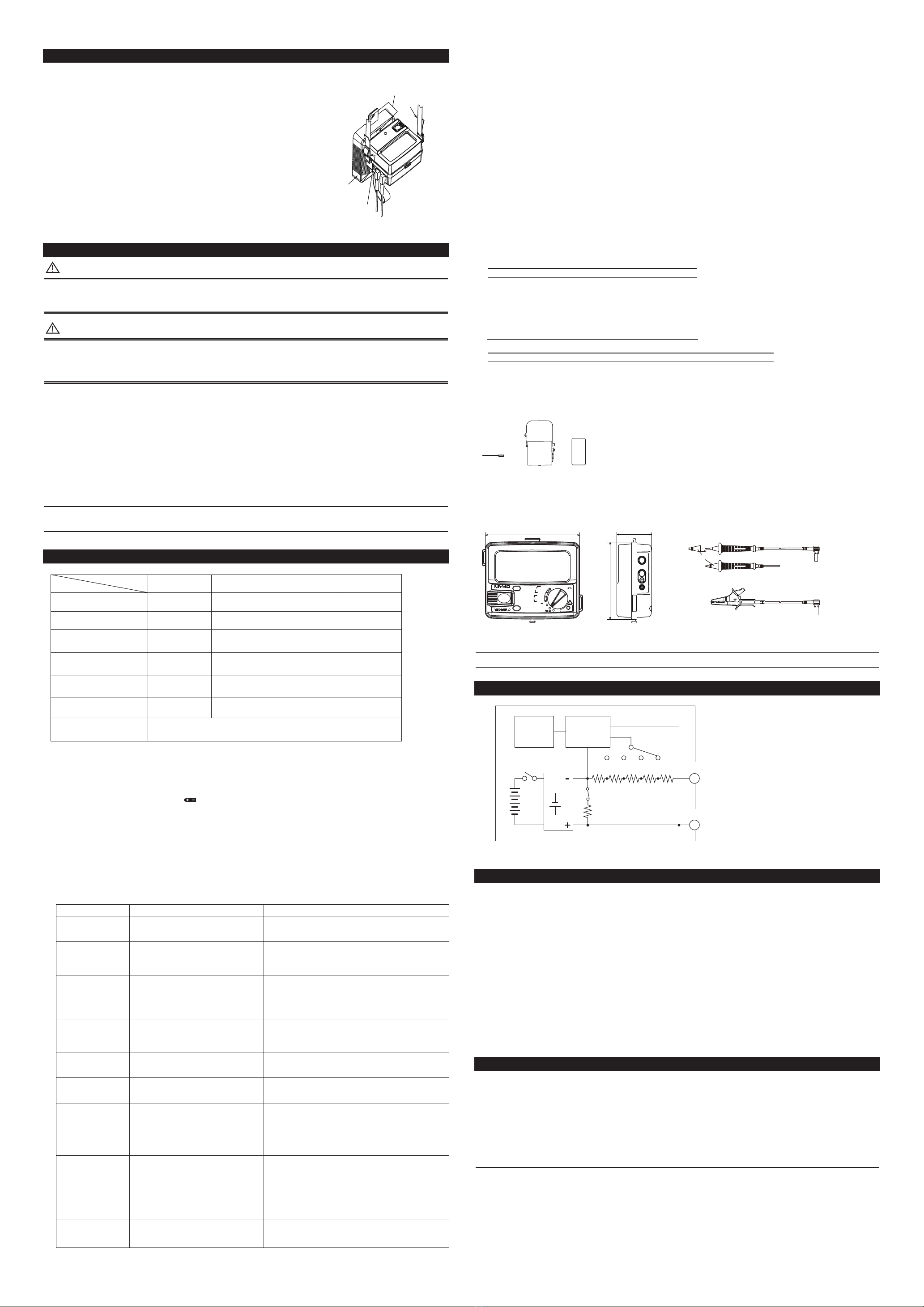
External Dimensions
125 (4.92)
103 (4.06)
52.5 (2.07)
Clr
Enter
Select
250V
1000V
500V
2000M
200M
OFF
600V MAX
V
125V
MEM
LIGHT
COMP
ALARM
INSULATION TESTER
1000V RELEASE
MEAS
PULL LOCK
Unit: mm
(approx. inch)
Earth probe (98002)
Line probe (98001)
Main unit
Cap
Cable length: approx. 1200 mm (approx. 47.24 inch)
NOTE
If the breaker pin (99011) is attached on the Line probe, detach the cap from Line probe.
7. Ontline of Measurement Principle
LINE
EARTH
LCD
MEAS
key
Four AA-size
batteries
High voltage
generator
circuit
A/D converter
and insulation
resistance
calculation
circuit Function (range)
selector switch
Discharge feature
Block Diagram of Insulation Resistance Measurement Circuit
8. Maintenance
8.1 Storage Conditions
• Temperature and humidity:-10°C to 60°C at 70% RH or less
• Remove the batteries before storing the tester.
• Avoid storing the tester in a location where there is:
moisture; exposure to direct sunlight;
a high-temperature heat source nearby;
exposure to severe mechanical vibrations;
a large amount of dust and/or salt, or a corrosive gas.
8.2 Removal of Dirt
Do not use solvents (such as paint thinners or benzine) or chemicals as they are likely to cause discoloration.
Wipe off dirt with a cloth dampened water or alcohol.
8.3 Calibration Cycle
It is recommended that the tester be calibrated once every year for correct operation;
ask Yokogawa to do the periodic calibration for you.
Authorized Representative in the EEA
Yokogawa Europe B.V. is the authorized representative of Yokogawa Meters & Instruments Corporation for
this product in the EEA. (EEA: European Economic Area)
To contact Yokogawa Europe B.V., see the separate list of worldwide contacts, PIM 113-01Z2.
4. Using Protection Cover and Shoulder Strap
The tester comes with a protection cover and shoulder strap as standard accessories.
• The protection cover can be used as a front cover
(for the display window) or as a bottom cover.
(It is set as the front cover when delivered from the factory.)
• Using the shoulder strap allows you to position the tester in front of
your chest for ease of reading.
Pass the strap through the shoulder strap guide and adjust the length of
the strap to allow you a good view of the tester.
• Remove the cover from the front, and attach it to the bottom using
the xing hole (B) on the surface of the cover.
This is useful when the diaplay is too close to your body to see clearly
(See the gure on the right).
• A belt on the cover which is tted with pieces of Velcro,
can be used to store the probes (Remove the probes from the tester
terminals when storing them).
Protection cover
fixing holes
Shoulder strap
Shoulder
strap guide
Protection
cover
A
B
5. Battery Replacement
WARNING
• Remove the probes from the tester and then turn off the MEAS key before opening the casing to
replace the batteries.
• Do not touch the MEAS key during replacement. Otherwise, a high voltage may be produced.
CAUTION
• Do not mix batteries of different types or new batteries with used ones.
• Always remove the batteries if the tester will not be used for a prolonged period of time.
If you store the tester with the batteries left installed, uid is likely to leak from them,
resulting in a malfunctioning of the instrument.
<Procedure>
1. Loosen the battery cover setscrew, and then slide the cover off of the main unit.
2. Replace all of the 4 batteries at the same time and make sure the polarities of
the new batteries are exactly as shown on the battery holder.
3. After replacing the batteries, attach the battery cover and tighten the setscrew.
■ Battery Life (Reference only)
For MY40 at rated 500 V/2000 MΩ:
Approximately 15 hours when in continuous operation with center value indicated
(approx. 50 MΩ; with standard supplied batteries).
NOTE
The data above is typical. Nevertheless, the battery life varies depending on the operating conditions.
Check the batteries before measurement.
6. Specications
125 V/200 MΩ 125 V/200 MΩ 500 V/2000 MΩ 1000 V/2000 MΩ
Center Value Indicated
(MΩ) 5
1st Effective Measuring Range
(MΩ) .0200 to 10.00
10.01 to 200
0 to .0199
2nd Effective Measuring Range
Upper Limit (MΩ)
2nd Effective Measuring Range
Lower Limit (MΩ)
Lower Measuring Limit of
Resistance (MΩ) 0.125
Rated Current (mA) 1 to 1.2
5
.0500 to 20.00
20.01 to 200
0 to .0499
0.25
1 to 1.2
50
1.000 to 500
501 to 2000
0 to .999
0.5
1 to 1.2
50
2.000 to 1000
1001 to 2000
0 to 1.999
2
0.5 to 0.6
AC Voltage Measuring Range
(V)  0 to 600
Rating
Item
Standard test conditions
Ambient temperature and humidity: 23 ±5°C at 45 to 75% RH
Position : Horizontal (within 5 degrees)
Inuence of external magnetic eld: Earth magnetism
Battery voltage : Within effective range of the battery
(the mark must not beindicated.)
Tolerances under the above conditions
Insulation resistance measurement: ±(2% of rdg + 6 dgt) within the 1st effective measuring range
± (5% of rdg + 6 dgt) within the 2nd effective measuring range (Lower limit)
±(5% of rdg) within the 2nd effective measuring range (Upper limit)
Zero value indicated: 6 dgt max.
AC voltage: ± (2% of rdg+6 dgt)
Conductor resistance measurement: ± (2% of rdg+8 dgt)
No-load voltage: within 130% of the rated voltage
Short-circuit current: 2 mA or less
Item Limit Test condition
Response time Digital indication: 3 seconds or less
Bar graph indication (static) value:
approx. 2 seconds
From the instant the resistors whose values correspond to
central indication and zero indications are abruptly connected,
to when the pointer reaches a level within tolerance
Effect of temperature ± (2% or rdg 6 dgt) 1st effective measuring range: maximum, center, and
minimumindicated values
Deviation from those values when ambient temperature is varied
from 20°C by ± 20°C.
Effect of humidity Within tolerance When the tester is left for 1 hour with the humidity at 90% RH
Effect of external
magnetic eld
1.2% or less of indication A change when the maximum, center, and minimum values of
the rst effective measuring range are indicated and
an external eld of 400 A/m
DC is applied in the most affected direction.
Effect of
AC component
10% or less of indication A change when a capacitor of 5 mF ±10% is connected in
parallel with a resistor the value of which is determined from
the rated measuring voltage and current,
and which is itself connected to the measuring terminals
Withstand voltage There must not be an abnormality
(between electric circuits and outer case). When a sine wave, or the like, is applied between
the electric circuits and the outer case at 5550 V AC and
50/60 Hz for 1 minute
Effect of vibration There is no structural damage and
the difference in errors must be
100% or less of the tester’s intrinsic errors
When a vibration frequency of 25 Hz and a peak-to-peak
amplitude of 1 mm is applied for 20 minutes in each of
three directions that are perpendicular to each other.
Effect of shock There is no structural damage and
the difference in errors must be
100% or less of the tester’s intrinsic errors
When a half-sine pulse shock of 1000 m/s2is applied in both
forward and reverse for 6 ms, three times in each of
three directions that are perpendicular to each other.
Effect of external
voltage
There must not be an abnormality. When an AC voltage 1.2-fold the rated measuring voltage at
50 Hz or 60 Hz is applied to the measuring terminals for
10 seconds with the MEAS key being on and then off.
Possible number of
measurements
Model MY40-01
Range Number of measurements
125 V/200 MΩ Approx. 1,600
250 V/200 MΩ Approx. 1,400
500 V/2000 MΩ Approx. 1,000
1000 V/2000 MΩ Approx. 700
Test point: The minimum measurable resistance that can
maintain the rated measuring voltage.
Measuring time: Five seconds each with approx. 25 seconds
between measurements
Backlight: Off
Battery used: Manganese battery
Ambient temperature: 20 ±2 °C; Relative humidity: 65 ±20%
(Battery testing conditions in compliance with JIS C8501)
Protection against
water, solid matters,
and dust penetration
Class IP 40:
Foreign substances of 1.0 mm or more in
diameter must not enter at all.
JIS C0920 compliance, with measuring probes attached to
the tester.
(IEC 60529: Degrees of protection provided by enclosures)
■ About This Manual
• The information contained in this manual is subject to change without notice.
• Copying or reproduction of any or all of the content of this manual without
Yokogawa's permission is strictly prohibited.
• Every effort has been made to ensure the information contained herein is accurate.
However, should any concerns, errors, or emissions come to your attention,
or if you have any comments, please contact us.

Other YOKOGAWA Test Equipment manuals

YOKOGAWA US300FM User manual

YOKOGAWA

YOKOGAWA US300FM User manual

YOKOGAWA DL 1540 User manual

YOKOGAWA

YOKOGAWA DL 1540 User manual

YOKOGAWA DL850E User manual

YOKOGAWA

YOKOGAWA DL850E User manual

YOKOGAWA 720930 User manual

YOKOGAWA

YOKOGAWA 720930 User manual

YOKOGAWA 30032A User manual

YOKOGAWA

YOKOGAWA 30032A User manual

YOKOGAWA PBL100 User manual

YOKOGAWA

YOKOGAWA PBL100 User manual

YOKOGAWA 30032A User manual

YOKOGAWA

YOKOGAWA 30032A User manual

YOKOGAWA AQ1210A User manual

YOKOGAWA

YOKOGAWA AQ1210A User manual

YOKOGAWA FC800D User manual

YOKOGAWA

YOKOGAWA FC800D User manual

YOKOGAWA SS380G User manual

YOKOGAWA

YOKOGAWA SS380G User manual

YOKOGAWA ScopeCorder DL950 User manual

YOKOGAWA

YOKOGAWA ScopeCorder DL950 User manual

YOKOGAWA 701928 User manual

YOKOGAWA

YOKOGAWA 701928 User manual

YOKOGAWA DLM5034 User manual

YOKOGAWA

YOKOGAWA DLM5034 User manual

YOKOGAWA AQ1210 Series User manual

YOKOGAWA

YOKOGAWA AQ1210 Series User manual

YOKOGAWA DL1640 User manual

YOKOGAWA

YOKOGAWA DL1640 User manual

YOKOGAWA ScopeCorder DL750P User manual

YOKOGAWA

YOKOGAWA ScopeCorder DL750P User manual

YOKOGAWA 2553A User manual

YOKOGAWA

YOKOGAWA 2553A User manual

YOKOGAWA DLM3022 User manual

YOKOGAWA

YOKOGAWA DLM3022 User manual

YOKOGAWA DL1720E User manual

YOKOGAWA

YOKOGAWA DL1720E User manual

YOKOGAWA DL6000 Series User manual

YOKOGAWA

YOKOGAWA DL6000 Series User manual

YOKOGAWA MY10-01 User manual

YOKOGAWA

YOKOGAWA MY10-01 User manual

YOKOGAWA DL1720E User manual

YOKOGAWA

YOKOGAWA DL1720E User manual

YOKOGAWA CA11E User manual

YOKOGAWA

YOKOGAWA CA11E User manual

YOKOGAWA DL2700 Series User manual

YOKOGAWA

YOKOGAWA DL2700 Series User manual

Popular Test Equipment manuals by other brands

Appion AV760 Quick Tips & Care Guide

Appion

Appion AV760 Quick Tips & Care Guide

FORM+TEST B17134 instruction manual

FORM+TEST

FORM+TEST B17134 instruction manual

Tektronix A621 instructions

Tektronix

Tektronix A621 instructions

Viavi ATC-5000NG Operation manual

Viavi

Viavi ATC-5000NG Operation manual

Ponovo T500 Series Hardware operation manual

Ponovo

Ponovo T500 Series Hardware operation manual

Fluke 71X Series Calibration manual

Fluke

Fluke 71X Series Calibration manual

Mountz TCA Operation & Calibration Instructions

Mountz

Mountz TCA Operation & Calibration Instructions

Cleerline SSF-TKITP-500 quick start guide

Cleerline

Cleerline SSF-TKITP-500 quick start guide

Hioki ST5680 Startup guide

Hioki

Hioki ST5680 Startup guide

MAHLE ROU250 Operation manual

MAHLE

MAHLE ROU250 Operation manual

Owon SDS6062 user manual

Owon

Owon SDS6062 user manual

Laser 6803 instructions

Laser

Laser 6803 instructions

Pharma Test PTB 311E manual

Pharma Test

Pharma Test PTB 311E manual

Boston D402 user manual

Boston

Boston D402 user manual

TechMate EMMIT quick start guide

TechMate

TechMate EMMIT quick start guide

TESTO 327 instruction manual

TESTO

TESTO 327 instruction manual

GW Instek C-1200 user manual

GW Instek

GW Instek C-1200 user manual

Klein Tools ET260 instruction manual

Klein Tools

Klein Tools ET260 instruction manual

manuals.online logo
manuals.online logoBrands
  • About & Mission
  • Contact us
  • Privacy Policy
  • Terms and Conditions

Copyright 2025 Manuals.Online. All Rights Reserved.