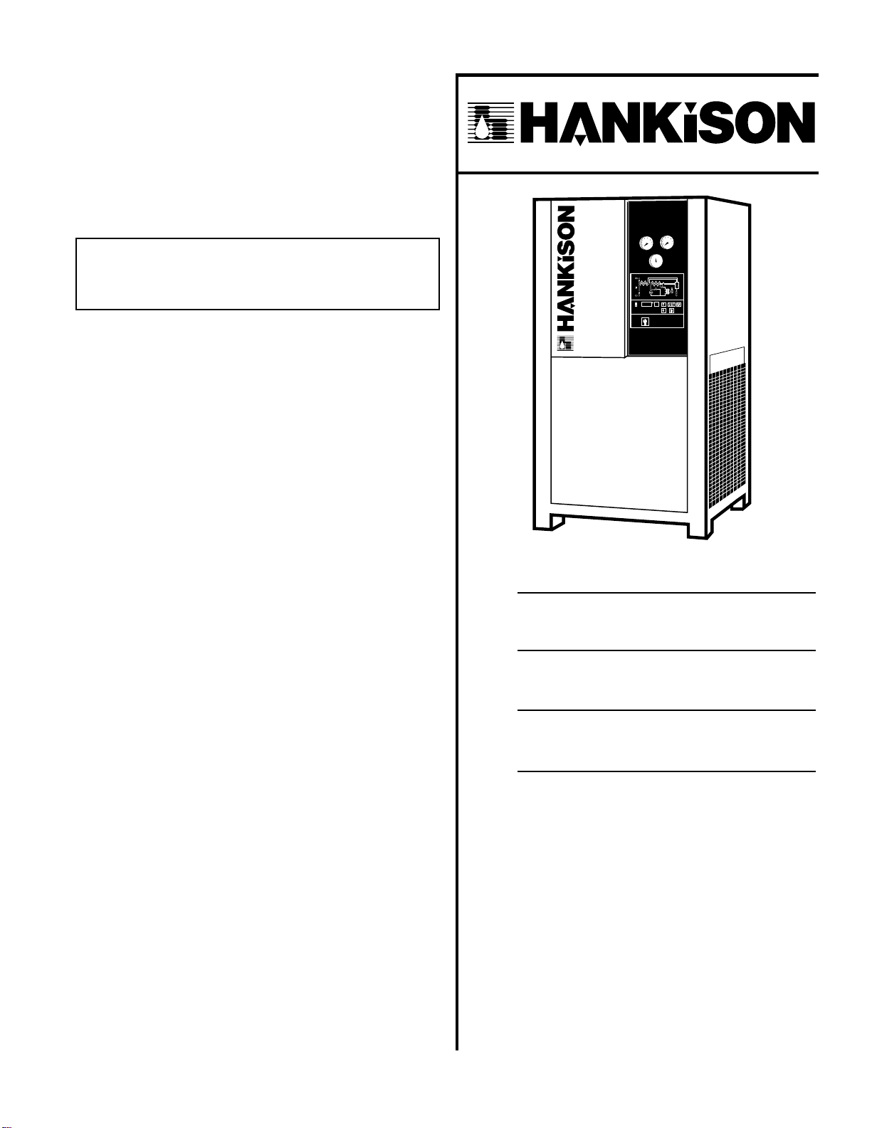
HANKISON PR500 User manual
1
7610.483.4B 8/01
INSTRUCTION MANUAL
Contents
GENERAL SAFETY INFORMATION ................................. 2
RECEIVING, MOVING, UNPACKING ............................... 2
1.0 INSTALLATION ........................................................ 3
2.0 OPERATION ........................................................... 6
3.0 MAINTENANCE ...................................................... 8
SIZING ........................................................................... 9
ENGINEERING DATA ..............................................10, 11
ELECTRICAL SCHEMATICS ......................................12, 13
CONTROL TRANSFORMER CONNECTIONS.................. 14
DIMENSIONS / WEIGHTS ............................................. 15
TROUBLESHOOTING .................................................... 16
PARTS LIST .............................................................17, 18
WARRANTY................................................................. 20
Models: PR500, PR600, PR700, PR800,
PR1000, PR1200, PR1600,
PR2000, and PR2300
SERVICE DEPARTMENT: (724) 746-1100
REFRIGERATED
TYPE
COMPRESSED
AIR DRYERS
®
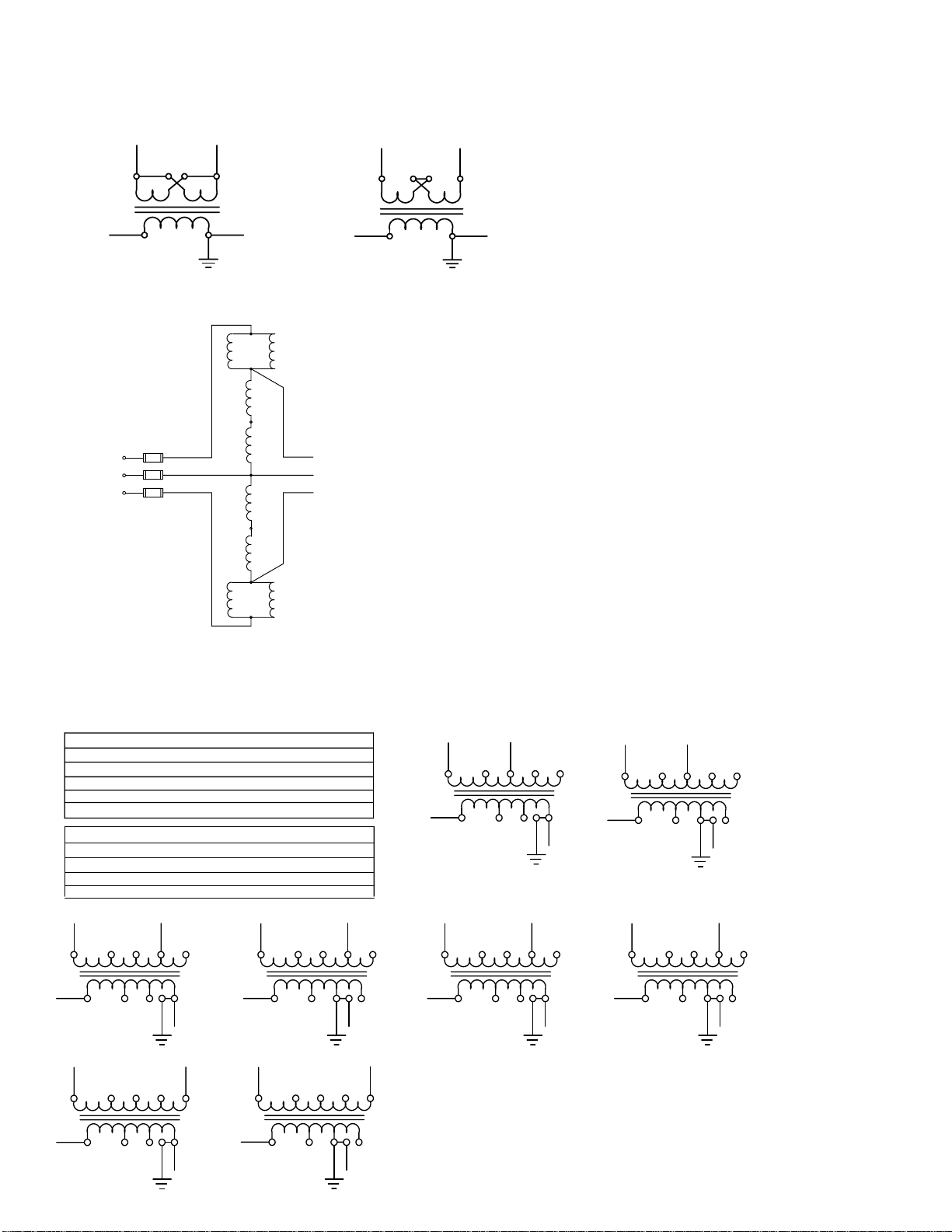
IMPORTANT - 380-420V/3ph/50Hz models - control
transformer is wired to operate on a voltage range of 391
to 418. For voltages outside this range rewire transformer
as shown on page 12.
M
M
2
RECEIVING, MOVING, AND UNP ACKING
A. RECEIVING
This shipment has been thoroughly checked, packed
and inspected before leaving our plant. It was received
in good condition by the carrier and was so acknowl-
edged.
Check for Visible Loss or Damage.If this shipment
shows evidence of loss or damage at time of delivery
to you, insist that a notation of this loss or damage be
made on the delivery receipt by the carrier’s agent.
B. UNPACKING
Check for Concealed Loss or Damage. When a ship-
ment has been delivered to you in apparent good
order, but concealed damage is found upon unpack-
ing, notify the carrier immediately and insist on his
agent inspecting the shipment. Concealed damage
claims are not our responsibility as our terms are F.O.B.
point of shipment.
C. MOVING
In moving or transporting dryer, do not tip dryer
onto its side.
All dryers are shipped to accomodate a fork lift truck.
When installing this unit, move it by means of a fork
lift or other suitable means. Never lift unit by hooking
on to the air inlet and outlet connections. Serious
damage may result.
D. STORAGE/SHUT-DOWN
IMPORTANT - WATER-COOLED UNITS - if unit is shut down in
below freezing temperatures, the water-cooled condenser
may freeze and cause permanent damage.
Condenser must be drained using drain cocks located on
the condenser when unit is shut down.
IMPORTANT - Do not store dryer in temperatures above
130°F, 54.4°C.
GENERAL SAFETY INFORMA TION
1. PRESSURIZED DEVICES:
This equipment is a pressure containing
device.
• Do not exceed maximum operating
pressure as shown on equipment serial number tag.
• Make sure equipment is depressurized before
working on or disassembling it for service.
2. ELECTRICAL:
This equipment requires electricity to
operate.
• Install equipment in compliance
with all applicable electrical codes.
• Standard equipment is supplied with electrical
enclosures not intended for installation in hazard-
ous environments.
• Disconnect power supply to equipment when
performing any electrical service work.
3. BREATHING AIR:
• Air treated by this equipment may
not be suitable for breathing
without further purification. Refer
to applicable standards and
specifications for the requirements
for breathing quality air.

3
NOTE: Outdoor installation: Standard dryers are designed
for indoor installation. Contact manufacturer if installing
outdoors.
1.0 INST ALLATION
1.1 Location
A. For typical placement in a compressed air system, see
drawing at right.
B. Air compressor intake - Locate air compressor so that
contaminants potentially harmful to the dryer (e.g.
ammonia) are not drawn into the air system.
C. Air-cooled units - Free air flow - Ambient air should be
free to flow across the refrigeration condenser. Do not
block either side of the cabinet. Leave at least 36 inches
(915 mm) clearance for free air flow.
COMPRESSOR AFTERCOOLER
SEPARATOR RECEIVER
TANK
DRYER
OIL
REMOVAL
FILTER
AUTOMATIC
DRAINS
1.2 Mounting
A. Mount dryer on firm level surface.
B. Dryers are furnished with removable shipping pads.
Remove prior to installation if desired. Dryers may be
bolted to the floor if desired.
IMPORTANT - Read prior to starting this equiptment.
LEFT SIDE VIEW FRONTVIEW RIGHT SIDEVIEW
AIR OUT AIR IN
DRAIN
ASSY.
(2)
MANUAL
DRAIN
AUTOMATIC
DRAIN ELECTRICAL
ENCLOSURE
ELECTRICAL
ENTRY
MANUAL
DRAIN
AUTOMATIC
DRAIN
CONTROL PANEL
SERIAL TAG
INSTRUCTION TAG
CONDENSER
BLOW OFF GUN
FOR CONDENSER CLEANING
4
1.3 Piping connections
If welding above unit make certain that
sparks are kept from contacting insulation around inlet
and outlet piping.
A. Air Inlet - Connect compressed air line from
air source to air inlet.
IMPORTANT: Refer to Serial Number Tag for maximum
working pressure. Do not exceed dryer’s Maximum
Working Pressure
NOTE: Install dryer in air system at highest pressure possible
(e.g. before pressure reducing valves)
NOTE: Install dryer at coolest compressed air temperature
possible. Maximum inlet compressed air temperature: 120°F
(49°C). If inlet air exceeds this temperature, precool the air
with an aftercooler.
B. Air Outlet - Connect air outlet to down-
stream air lines.
C. By-pass piping - If servicing the dryer
without interrupting the air supply is desired,
piping should include inlet and outletvalves and
an air by-pass valve.
D. Condensate Drain
1. Manual Drains - Petcocks (2) for manual
draining are attached to the manual drain
lines in the cabinet. Remove petcocks and
install into manual drain couplings. Make
sure petcocks are closed.
2. Automatic Drains - Drain lines can be run
from Automatic Drain outlets (2) to the plant
drainage system.
NOTE: Condensate may contain oil. Comply with
applicable laws concerning proper disposal.
NOTE: Discharge is at system pressure. Anchor drain line.
E. Water cooled models - cooling water inlet and outlet
1. Connect cooling water supply to cooling water inlet
coupling.
2. Connect cooling water return line to cooling water
outlet coupling.
NOTE: Strainer and water regulating valve are supplied on
water cooled models.
1.4 Electrical connections
IMPORTANT - Use copper supply wires only.
A. Unit is designed to operate on the voltage,
phase, and frequency listed on serial number tag.
B. Electrical entry is through hole in cabinet and
into electrical enclosure. Connect power source to
terminal strip in electrical enclosure as shown on
Electrical Schematic attached to dryer.
NOTE: Refrigeration condensing unit is designed to run
continuously and should NOT be wired to cycle on/off with
the air compressor.
PETCOCK
INSTALLED

5
1
22
45
MIN.
1
7
15
SEC..
manual
overide
POWER
ON
ELECTRIC DRAIN
(Optional with Three Light Control Panel)
ISOLATION VALVE
RESERVOIR WITH
INTERNAL
STRAINER
TIMER
MANUAL DRAIN
TUBE
SET TIME VALVE OPENS
SET TIME BETWEEN
OPERATIONS
(VALVE CLOSED)
VALVE
ENERGIZED
LIGHT
TIMER ENERGIZED
LIGHT
DRAIN TEST BUTTON
1.5 Automatic condensate drains
A. Models with electric drains
1. Verify that isolation valves are open.
2. Verify time settings.
After dryer is operating, verify that valve remains open
long for all condensate to be ejected from the system.
If all condensate is not ejected during valve open time,
shorten time between operations.
a. MODELS WITH STANDARD CONTROL PANEL AND
ELECTRIC DRAIN - Drain timers (2) are factory set
for 5 minutes between operations (valve closed)
and 5 seconds valve open time
b. MODELS WITH DIGITAL CONTROL PANEL - TIME
BETWEEN OPERATIONS (valve closed) is factory set
for 2.5 minutes, valve open time is not adjustable.
See instructions under 2.3 to adjust time.
B. Models with mechanical drains
1. Verify that isolation valves are open.
MECHANICAL DRAIN
ISOLATION
VALVE
MANUAL DRAIN
AUTOMATIC
DISCHARGE
MANUAL DRAIN
AUTOMATIC DRAIN
ISOLATION VALVE
SOLENOID VALVE
RESERVOIR WITH
INTERNAL STRAINER
ELECTRIC DRAIN
(Supplied with digital control panel)

6
2.3 Operating check points – Check the following on
a periodic basis:
A. Power-on light glows indicating power to the dryer.
B. Compressor-on light (green) glows indicating the
refrigerator compressor is operating.
C. Standard Panels
1. High air temperature warning light is out. The high air
temperature warning light will illuminate when unit is
energized. Light should go out approximately 15
minutes after start-up. If light remains lit after 30
minutes or lights again after going out, refer to
Troubleshooting Guide.
2. Refrigerant pressure cut out light is out.
D. Digital panels - Check for alarms - compressor on light -
red indicating compressor off because of refrigerant
pressure cut out. High temperature alarm. High level
alarm (optional).
E. Suction pressure gauge indicates proper low side
refrigerant pressure. (Refer to engineering data)
F. Outlet pressure gauge - Compare with pressure at inlet
to dryer to determine if a higher than normal pressure
drop exists.
G. Inlet temperature gauge (supplied on models with
Standard Control Board) - inlet temperature should read
below 120°F (49°C).
H. Condensate is discharging from drain
2.0 OPERA TION
2.1 Minimum/maximum operating conditions
A. Maximum inlet air pressure: refer to unit serial
number tag
B. Minimum inlet air pressure: 20 psig (1.4 kgf/cm2)
C. Maximum inlet air temperature: 120°F (49°C)
D. Maximum ambient temperature:
Air-cooled models: 110°F (43°C)
Water-cooled models: 130°F (54°C)
E. Minimum ambient temperature: 35°F (2°C)
2.2 Start-up
NOTE: Start unit before introducing air flow. High
pressure switch has a manual reset. If refrigerant pressure
cut-out (compressor off light) illuminates during start-up,
reset switch.
A. Control Panel
1. After making sure that on/off switch is off (“O” ),
energize dryer. Green power-on light will glow.
2. On water-cooled units - after 24 hours start flow
of water through condenser.
3. After 24 hours, energize compressor by positioning
the on/off switch in the on ("I") position. Green
compressor-on light will glow.
NOTE: COMPRESSOR ROTATION - Model 800 thru 2300
only - ensuring proper compressor rotation - Dryer contains
a scroll compressor which must rotate in the proper
direction. If after starting dryer an unusual noise is heard
and the suction pressure fails to drop into the normal range,
stop dryer, reverse two power leads, restart, and verify that
suction pressure is reading as stated on serial no. tag.
B. Alarms
1. High temperature alarm - If the Lowest Air Tempera-
ture exceeds the alarm set point, the red high
temperature warning light will glow.
2. Refrigerant pressure cut out alarm - If the high or low
refrigerant pressure set points have been exceeded,
the dryer will shut down. The green compressor-on
light will turn off and the red refrigerant pressure cut
out light will glow.
NOTE: High refrigerant pressure switch has a manual
reset. After correcting fault, manually reset switch to
resume operation.
C. Drain Test Button (models with electric drains)
Standard Control Panel: Push test button on drain valve
to manually activate. Drain energized light will glow.
Digital Control Panel: Push test button on digital board.
2.4 Using the Digital Panel
A. Function Lights
1. Power-on light - indicates power to dryer
2. Compressor-on light - indicates power to
control circuit, refrigeration compressor should
be running
3. Drain energized light - indicates power to solenoid
valve, drain should be open
B. Numeric Display - When the on/off switch is placed in
the ON position, the Numeric Display indicates Lowest Air
Temperature. Additional temperatures, alarm setpoints,
and electric drain adjustment are available by pressing
the mode selector button in the following sequence:
1. Display indicates Outlet Air Temperature. Outlet
temperature light glows.
2. Display indicates Ambient Temperature. Ambient
temperature light glows.
3. Display indicates Inlet Temperature Alarm set point.
Green light glows in Temperature Alarm box. Set point
may be changed by pushing up and down arrows.
4. Display indicates Lowest Air Temperature Alarm set
point. Green light glows in Temperature Alarm box. Set
point may be changed by pushing up and down arrows.
5. Used on models with Electric Drains (if dryer is not
equipped with electric drain sequence through this
step) Display indicates Electric Drain Closed time in
minutes and tenths of a minute. Green light in drain
time box glows. Time between valve openings may be
changed by pushing up and down arrows.
6. Display indicates inlet air temperature. Inlet
temperature light glows.
-
IMPORTANT: Energize dryer disconnect switch 24 hours
before refrigeration compressor is started! Never use
the disconnect switch to shut-down the dryer for a
extended period of time (except for repair). Failure to
follow these instructions may result in a non-warrant-
able compressor failure.
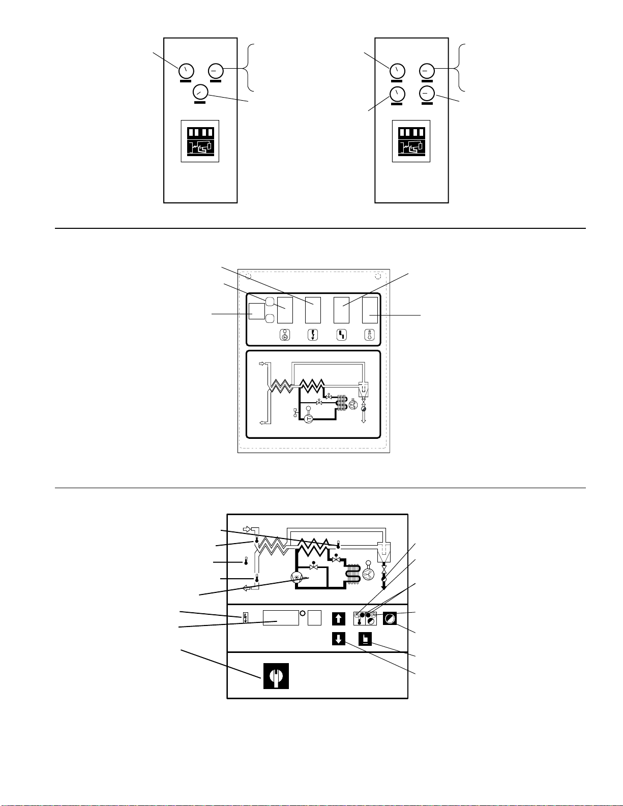
7
PRESSURE
OUT GAUGE
DIGITAL PANEL-
Pressure In Gauge
or
STANDARD PANEL-
Temperature In Gauge
REFRIGERANT SUCTION
PRESSURE GAUGE
PRESSURE
OUT GAUGE
HEAD
PRESSURE
GAUGE
DIGITAL PANEL-
Pressure In Gauge
or
STANDARD PANEL-
Temperature In Gauge
REFRIGERANT SUCTION
PRESSURE GAUGE
CONTROL PANEL FOR MODELS 1600, 2000, 2300CONTROL PANEL FOR MODELS 500 TO 1200
* Green - compressor on
Red - compressor off because of
refrigerant pressure cut out
COMPRESSOR ON LIGHT (GREEN)
POWER ON LIGHT (GREEN)
STANDARD CONTROL PANEL
ON/OFF SWITCH
M
I
O
M
PI
M
REFRIGERANT PRESSURE CUT
OUT LIGHT (RED)
HIGH TEMPERATURE
WARNING LIGHT (RED)
M
M
DRAIN ENERGIZED LIGHT
HIGH TEMPERATURE
ALARM LIGHT (RED)
MODE INDICATOR (GREEN)
OPTIONAL HIGH
WATER LEVEL ALARM
ELECTRIC DRAIN TEST BUTTON
MODE SELECTOR
ALARM/SET TEST BUTTONS
DIGITAL CONTROL PANEL
LOWEST AIR TEMPERATURE LIGHT
AIR INLET TEMPERATURE LIGHT
AMBIENT TEMPERATURE LIGHT
AIR OUTLET TEMPERATURE LIGHT
COMPRESSOR ON LIGHT*
POWER ON LIGHT
DIGITAL DISPLAY
ON/OFF SWITCH

8
2.5 Shutdown and Restart
A. Shutdown
1. Turn on/off switch to off "O". Leave dryer energized
unless servicing.
B. Restart
NOTE: Dryer should be energized 24 hours prior to start-up.
1. Make certain air inlet and outlet isolation valves
are closed.
2. Turn on/off switch to on "I"
3. After 15 minutes, slowly open isolation valves and close
by-pass valve.
3.0 MAINTENANCE
3.1 Air-cooled models
A. Condenser coil - Clean off accumulated dust and dirt
monthly.
NOTE: A blow-gun is supplied with dryer for this purpose.
Remove condenser screen to access blow gun.
3.2 Water-cooled models
A. Strainer - Clean strainer periodically to prevent
restriction of water flow
3.3 Automatic condensate drains
A. Check daily to be sure automatic drain is discharging.
B. Manually drain separator weekly by opening
manual drain.
C. Electric drains - periodically clean strainer in
drain reservoirs.
D. Mechanical drains - Rebuild drain mechanisms annually.
Use repair parts kit - 05.7501-03.

9
OPERATING PRESSURE psig / kg/cm2
AIR FLOW 60 / 4.2 100 / 7 180 / 12.6 200 / 14.0
2.0 x rated flow 5.4 3.5 2.1 1.9
1.5 x rated flow 3.2 2.1 1.2 1.1
1.2 x rated flow 2.1 1.4 0.8 0.7
OUTLET DEWPOINT
DEW POINT
TEMPERATURE MULTIPLIER
°F°C
38 3 1.0
40 4 1.1
45 7 1.2
50 10 1.3
COOLING MEDIUM*
AMBIENT
TEMPERATURE MULTIPLIER
°F°C
80 27 1.12
90 32 1.06
100 38 1.00
110 43 0.94
INLET COMPRESSED AIR CONDITIONS
INLET INLET TEMPERATURES
PRESSURES 80°F90°F 100°F 110°F 120°F
psig kg/cm227°C32°C38°C 43°C49°C
50 3.5 1.35 1.05 0.84 0.69 0.56
80 5.6 1.50 1.17 0.95 0.79 0.66
100 7.0 1.55 1.23 1.00 0.82 0.70
125 8.8 1.63 1.31 1.07 0.91 0.74
150 10.5 1.70 1.37 1.13 0.95 0.80
175 12.3 1.75 1.42 1.18 0.99 0.84
200 14.0 1.80 1.47 1.22 1.03 0.89
scfm x 0.0286 = m3/min
TABLE 2
Air capacity correction factors (multipliers) TABLE 3
Pressure drop correction factors (multipliers)
* Air-cooled models; water-cooled models use 1.15 multiplier if cooling
water is below 95°F, 35°C
TABLE 1
Rated capacity and Pressure @ 100 psig inlet pressure,
100°F inlet temperature, and 100°F ambient temperature
MODEL 500 600 700 800 1000 1200 1600 2000 2300
scfm scfm scfm scfm scfm scfm scfm scfm scfm
Rated Capacity of 60 Hz 500 600 700 800 1000 1200 1600 2000 2300
Air-Cooled Models (scfm) 50 Hz 500 560 580 745 830 1000 1330 1660 1910
Pressure Drop (psi) 60 Hz 3.2 3.6 4.0 3.6 4.2 4.1 3.9 4.7 5.0
50 Hz 3.2 3.2 2.9 3.2 3.0 2.9 2.8 3.4 3.6
n
SIZING
Determining dryer capacity at actual operating conditions
To determine the maximum inlet flow capacity of a dryer at various operating conditions, multiply the rated capacity from
Table 1 by the multipliers shown in Table 2.
EXAMPLE: How many scfm can a model 1000 handle when the compressed air to be dried is at 80 psig and 90°F; ambient air
temperature is 80°F; and a 38°F dew point temperature is desired?
ANSWER: 1000 x 1.17 x 1.12 x 1.0 = 1310 scfm.
Pressure Drop
To determine pressure drop at increased flows, multiply the pressure drop at rated conditions from Table 1 by the multiplier
shown in Table 3 for the appropriate air flow rate and operating pressure.
EXAMPLE: What is the pressure drop across a model 1000 when flowing 1500 scfm at 200 psig ?
ANSWER: 1500/1000 = 1.5; multiplier below at 1.5 and 200 psi = 1.1; 1.1 x 4.2 psi = 4.6 psi.

10
ENGINEERING DA TA
MODELS 500 600 700 800 1000
MINIMUM- MAXIMUM OPERATINGCONDITIONS
Max. Inlet Air Pressure ( compressed air @ inlet dryer Std. 200 psig (14 bar)
Optional 300 psig (21 bar)
Max. Inlet Air Temperature (compressed air @ inlet dryer) 120°F (49°C)
Min.- Max. Ambient Temperature (Air Cooled) 35°F (1.7°C) -110°F (43°C)
Min.- Max. Ambient Temperature (Water Cooled) 35°F (1.7°C) -130°F (54°C)
REFRIGERATIONSYSTEM DATA
Condensing Unit Mfg. Copeland
Compressor Type Hermetic - Non-Cycling Hermetic Scroll / Non-cycling
Refrigeration Compressor Horsepower 3 3 3 4 4
BTU/HR - Refrigeration Only @ 35°F (1.7°C) Evaporator
& 100°F (38°C) Ambient 60/50 Hz 28592 / 23827 28592 / 23827 28592 / 23827 42140 / 35117 42140 / 35117
Outlet Air Temperature (nominal at rated conditions) 85°F (29°C)
Refrigerant Type R-134A R-134A R-134A R-404A R-404A
Refrigerant Charge See dryer serial number tag
Suction Pressure Setting psig (bar) 30.5 (2.1) 30.5 (2.1) 30.5 (2.1) 78 (5.4) 78 (5.4)
Compressor Control Ranges (out/in) (psig) A/C High 281 - 190 281 - 190 281 - 190 450 - 350 450 - 350
A/C Low 24 - 34 24 - 34 24 - 34 67 - 84 67 - 84
Compressor Control Ranges (out/in) (psig) W/C High 200 - 160 200 - 160 200 - 160 320 - 280 320 - 280
W/C Low 22 - 34 22 - 34 22 - 34 67 - 84 67 - 84
Condenser Fan Switch Setting (in/ out) (psig) Fan 1 113 - 78 113 - 78 113 - 78 300 - 230 300 - 230
(air-cooled models only) Fan 2 183 - 124 183 - 124 183 - 124 - -
Air Flow Across Condenser (cfm) 60/50 Hz 2650 / 2208 2650 / 2208 2650 / 2208 3400 / 2833 3400 / 2833
CONDENSERCOOLING WATERREQUIREMENTS
(water cooled models)
Recommended Water Pressure psig (bar) * -40 (2.8) Min. - 120 (8.4) Max.
gpm of water @ 85°F cooling water 60/50 Hz 6 / 5 7 / 6 8 / 7 9 / 8 12 / 10
ELECTRICALDATA
Nominal Voltage 208-230/3/60 208-230/3/60 208-230/3/60 208-230/3/60 208-230/3/60
Max. - Min. Voltage 253 - 187 253 - 187 253 - 187 253 - 187 253 - 187
Amperage Draw Total Full Load ** 22.9 22.9 22.9 19.1 19.1
Compressor Rated Load (amps) 20.7 20.7 20.7 15 15
Compressor Locked Rotor (amps) 90 90 90 99 99
Unit Protection Fuse Size (amps) ** 25 25 25 20 20
Branch Circuit Fuse Size (amps) Max. *** 45 45 45 35 35
Watts @ 35°F (1.7°C) Evaporator & 100°F (38°C) Ambient 3600 3600 3600 5020 5020
Resistance (ohms) Three phase (total) 0.853 0.853 0.853 - -
Nominal Voltage 460/3-60 460/3-60 460/3-60 460/3-60 460/3-60
Max. - Min. Voltage 506 - 414 506 - 414 506 - 414 506 - 414 506 - 414
Amperage Draw Total Full Load ** 11 11 11 10.3 10.3
Compressor Rated Load (amps) 9.9 9.9 9.9 8.2 8.2
Compressor Locked Rotor (amps) 45 45 45 49.5 49.5
Unit Protection Fuse Size (amps) ** 12-1/2 12-1/2 12-1/2 12-1/2 12-1/2
Branch Circuit Fuse Size (amps) Max. *** 20 20 20 20 20
Watts @ 35°F (1.7°C) Evaporator & 100°F (38°C) Ambient 3600 3600 3600 5020 5020
Resistance (ohms) Three phase (total) .0.853 0.853 0.853 - -
Nominal Voltage 200-220/3/50 200-220/3/50 200-220/3/50 200-220/3/50 200-220/3/50
Max. - Min. Voltage 242 - 180 242 - 180 242 - 180 242 - 180 242 - 180
Amperage Draw Total Full Load ** 22.9 22.9 22.9 19.1 19.1
Compressor Rated Load (amps) 20.7 20.7 20.7 15 15
Compressor Locked Rotor (amps) 90 90 90 99 99
Unit Protection Fuse Size (amps) ** 25 25 25 20 20
Branch Circuit Fuse Size (amps) Max. *** 45 45 45 35 35
Watts @ 35°F (1.7°C) Evaporator & 100°F (38°C) Ambient 2929 2929 2929 4183 4183
Resistance (ohms) Three phase (total) 0.853 0.853 0.853 - -
Nominal Voltage 400/3/50 400/3/50 400/3/50 400/3/50 400/3/50
Max. - Min. Voltage 462 - 342 462 - 342 462 - 342 462 - 342 462 - 342
Amperage Draw Total Full Load ** 11 11 11 10.3 10.3
Compressor Rated Load (amps) 9.9 9.9 9.9 8.2 8.2
Compressor Locked Rotor (amps) 45 45 45 49.5 49.5
Unit Protection Fuse Size (amps) ** 12-1/2 12-1/2 12-1/2 12-1/2 12-1/2
Branch Circuit Fuse Size (amps) Max. *** 20 20 20 20 20
Watts @ 35°F (1.7°C) Evaporator & 100°F (38°C) Ambient 2929 2929 2929 4183 4183
Resistance (ohms) Three phase (total) 0.853 0.853 0.853 - -
Nominal Voltage 575/3/60 575/3/60 575/3/60 575/3/60 575/3/60
Max. - Min. Voltage 632 - 518 632 - 518 632 - 518 632 - 518 632 - 518
Amperage Draw Total Full Load ** 11 11 11 9.8 9.8
Compressor Rated Load (amps) 9.9 9.9 9.9 8.2 8.2
Compressor Locked Rotor (amps) 45 45 45 40 40
Unit Protection Fuse Size (amps) ** 12-1/2 12-1/2 12-1/2 12-1/2 12-1/2
Branch Circuit Fuse Size (amps) Max. *** 20 20 20 20 20
Watts @ 35°F (1.7°C) Evaporator & 100°F (38°C) Ambient 3600 3600 3600 5020 5020
Resistance (ohms) Three phase (total) 0.853 0.853 0.853 --
* Allows continued operation with some restriction in the water strainer, * * Air cooled models only, * * * HACR type per NEC

11
MODELS 1200 1600 2000 2300
MINIMUM- MAXIMUM OPERATINGCONDITIONS
Max. Inlet Air Pressure ( compressed air @ inlet dryer ) Std. 200 psig (14 bar)
Optional 300 psig (21 bar)
Max. Inlet Air Temperature (compressed air @ inlet dryer) 120°F (49°C)
Min.- Max. Ambient Temperature (Air Cooled) 35°F (1.7°C) -110°F (43°C)
Min.- Max. Ambient Temperature (Water Cooled) 35°F (1.7°C) -130°F (54°C)
REFRIGERATIONSYSTEM DATA
Condensing Unit Mfg. Copeland
Compressor Type Hermetic Scroll / Non-cycling
Refrigeration Compressor Horsepower 6 7-1/2 10 12
BTU/HR - Refrigeration Only @ 35°F (1.7°C) Evaporator
& 100°F (38°C) Ambient 60/50 Hz 57310 / 47758 69370 / 57808 92550 / 77125 106090 / 88408
Outlet Air Temperature (nominal at rated conditions) 85°F (29°C)
Refrigerant Type R-404A R-404A R-404A R-404A
Refrigerant Charge See dryer serial number tag
Suction Pressure Setting psig (bar) 78 (5.4) 78 (5.4) 78 (5.4) 78 (5.4)
Compressor Control Ranges (out/in) (psig) A/C High 450 - 350 450 - 350 450 - 350 450 - 350
A/C Low 67 - 84 67 - 84 67 - 84 67 - 84
Compressor Control Ranges (out/in) (psig ) W/C High 320 - 280 320 - 280 320 - 280 320 - 280
W/C Low 67 - 84 67 - 84 67 - 84 67 - 84
Condenser Fan Switch Setting (in/out) (psig) Fan 1 300 - 230 300 - 230 300 - 230 300 - 230
(air-cooled models only) Fan 2 325 - 255 325 - 255 325 - 255 325 - 255
Air Flow Across Condenser (cfm) 60/50 Hz 4230 / 3525 5300 / 4417 4900 / 4083 4900 / 4083
CONDENSER COOLING WATER REQUIREMENTS (watercooledmodels)
Recommended Water Pressure (psig) * 40 Min. - 120 Max.
gpm of water @ 85°F cooling water 60/50 Hz 14 / 12 21 / 18 27 / 23 35 / 30
ELECTRICALDATA
Nominal Voltage 208-230/3/60 208-230/3/60 208-230/3/60 208-230/3/60
Max. - Min. Voltage 253 - 187 253 - 187 253 - 187 253 - 187
Amperage Draw Total Full Load ** 26.9 39.3 53.1 62.8
Compressor Rated Load (amps) 23.9 30.9 44.9 54.4
Compressor Locked Rotor (amps) 156 189 278 350
Unit Protection Fuse Size (amps) ** 30 45 60 70
Branch Circuit Fuse Size (amps) Max. *** 50 70 100 125
Watts @ 35°F (1.7°C) Evaporator & 100°F (38°C) Ambient 7540 9630 14370 17490
Resistance (ohms) Three phase (total) - - - -
Nominal Voltage 460/3-60 460/3-60 460/3-60 460/3-60
Max. - Min. Voltage 506 - 414 506 - 414 506 - 414 506 - 414
Amperage Draw Total Full Load ** 11.1 20 25.5 29.6
Compressor Full Load (amps) 9.3 16.2 21.7 25.8
Compressor Locked Rotor (amps) 70 94 127 158
Unit Protection Fuse Size (amps) ** 15 25 30 35
Branch Circuit Fuse Size (amps) Max. *** 20 40 50 60
Watts @ 35°F (1.7°C) Evaporator & 100°F (38°C) Ambient 7540 9630 14370 17490
Resistance (ohms) Three phase (total) - - - -
Nominal Voltage 200-220/3/50 200-220/3/50 200-220/3/50 200-220/3/50
Max. - Min. Voltage 242 - 180 242 - 180 242 - 180 242 - 180
Amperage Draw Total Full Load ** 26.9 39.3 53.1 62.8
Compressor Rated Load (amps) 23.9 30.9 44.9 54.4
Compressor Locked Rotor (amps) 156 189 278 350
Unit Protection Fuse Size (amps) ** 30 45 60 70
Branch Circuit Fuse Size (amps) Max. *** 50 70 100 125
Watts @ 35°F (1.7°C) Evaporator & 100°F (38°C) Ambient 6283 8025 11975 14575
Resistance (ohms) Three phase (total) - - - -
Nominal Voltage 400/3/50 400/3/50 400/3/50 400/3/50
Max. - Min. Voltage 462 - 342 462 - 342 462 - 342 462 - 342
Amperage Draw Total Full Load ** 11.1 20 25.5 29.6
Compressor Rated Load (amps) 9.3 16.2 21.7 25.8
Compressor Locked Rotor (amps) 74 99 127 167
Unit Protection Fuse Size (amps) ** 15 25 30 35
Branch Circuit Fuse Size (amps) Max. *** 20 40 50 60
Watts @ 35°F (1.7°C) Evaporator & 100°F (38°C) Ambient 6283 8025 11975 14575
Resistance (ohms) Three phase (total) - - - -
Nominal Voltage 575/3/60 575/3/60 575/3/60 575/3/60
Max. - Min. Voltage 632 - 518 632 - 518 632 - 518 632 - 518
Amperage Draw Total Full Load ** 9.3 15.2 20 24
Compressor Rated Load (amps) 7.9 11.8 16.6 20.6
Compressor Locked Rotor (amps) 54 74 100 125
Unit Protection Fuse Size (amps) ** 12-1/2 17-1/2 25 30
Branch Circuit Fuse Size (amps) Max. *** 15 25 40 50
Watts @ 35°F (1.7°C) Evaporator & 100°F (38°C) Ambient 7540 9630 14370 17490
Resistance (ohms) Three phase (total) - - - -
* Allows continued operation with some restriction in the water strainer, * * Air cooled models only, * * * HACR type per NEC
ENGINEERING DA TA

12
L1
4HP THRU 12HP 575 VOLT UNITS
3HP THRU 12HP 230/460 VOLT AND
(1) CUSTOMER ELECTRICAL CONNECTIONS (TERMINAL STRIP)
(1)
(1)
(1)
L3 L3
L2
L3 L3 L2 L1
(1)
L1
L1
8FU
(1) CUSTOMER ELECTRICAL CONNECTION (ENTRY ENCLOSURE)
3HP 575 VOLT UNITS ONLY
(1)
(1)
(1) 9FU
(1) 7FU
6FU - FUSE, LITTELFUSE, KLDR 1/2, 600V
CON 4LT
3LT
4. DISCHARGE TEMPERATURE SWITCH IS ONLY USED ON
3. SOLID STATE MOTOR PROTECTOR IS ONLY USED ON
1. REMOVE FAN MOTORS AND FAN SWITCHES FOR WATER
2. 4HP UNITS HAVE ONLY ONE (1) FAN MOTOR.
4HP AND 6HP UNITS.
7-1/2HP THRU 12HP UNITS.
COOLED UNITS.
NOTES
LOW AMBIENT
(OPTIONAL)
2SOL
1SOL
TDR
PBS
CR
DTS
SSMP HPS
TDR
LPS
CON
HTS
R
R
CR-1
CR-5
LOW AMBIENT
TIME DELAY
(OPTIONAL)
CR-9
ALARM CONTACT RATINGS
7A @ 240VAC
7.5A @ 30VDC
7.5A @ 120VAC
CR
CR
ALARM CONTACTS (OPTIONAL)
TAS - THERMOSTAT
TDR - TIME DELAY RELAY
2T - LOW AMBIENTTRANSFORMER
2HTR - LOW AMBIENT HEAT TAPE
3HTR - LOW AMBIENT HEAT TAPE
CONTACTS
SEE NOTES 3
SEE NOTES 4
(OPTIONAL)
ALARM
2LT
1LT
230/400/460/575 VOLT
L2
5FU
2T
TAS 3HTR
TAS 2HTR
6FU
1
XX
GND
2
115V
CONNECTIONS
575 VOLT SEE TRANSFORMER
FOR 3HP UNITS
4FU
L3
1T
CON
1FU
1X
GND
2
115V
X
G
SSMP
G
3FU
2FU
SEE TRANSFORMER
DETAILS FOR
CONNECTIONS
1FPS
2FPS
USE COPPER
SUPPLY WIRE ONLY
L1 CON
CON 1HTR
MTR
5FU - FUSE, LITTELFUSE, KLDR 1/2, 600V
4FU - FUSE, LITTELFUSE, FLM 1-1/4, 250V
CR - CONTROL RELAY
OPTIONAL FEATURES BELOW
4LT - REFRIGERANT FAULT LIGHT
2SOL - ELECTRIC DRAIN VALVE
1SOL - ELECTRIC DRAIN VALVE
SSMP - SOLID STATE MOTOR PROTECTOR
DTS - DISCHARGE TEMPERATURE SWITCH
SEE NOTE 3
FM - FAN MOTOR
CON - CONTACTOR
MTR - COMPRESSOR
1LT - POWER ON LIGHT
1T - CONTROL TRANSFORMER
3LT - HIGH TEMPERATURE LIGHT
2LT - COMPRESSOR ON LIGHT
HTS - HIGH TEMPERATURE SWITCH
FPS - FAN PRESSURE SWITCH
LPS - LOW PRESSURE SWITCH
1FM SEE NOTE 1
SEE NOTE 2
2FM
3FU - FUSE, LITTELFUSE, KLDR 1/2, 600V
2FU - FUSE, LITTELFUSE, KLDR 1/2, 600V
1FU - FUSE, LITTELFUSE, FLM 6/10, 250V
1HTR - CRANKCASE HEATER
HPS - HIGH PRESSURE SWITCH
PBS - DRYER-ON/OFF SWITCH
LEGEND
(OPTIONAL)
(OPTIONAL)
ELECTRICAL CONNECTIONS
WIRING DIAGRAM (ST ANDARD CONTROL P ANEL)

13
SUPPLY WIRE ONLY
USE COPPER
FOR 3HP UNITS
575 VOLT SEE TRANSFORMER
CONNECTIONS
230/400/460/575 VOLT
COOLED UNITS.
7-1/2HP THRU 12HP UNITS.
4HP AND 6HP UNITS.
2. 4HP UNITS HAVE ONLY ONE (1) FAN MOTOR.
1. REMOVE FAN MOTORS AND FAN SWITCHES FOR WATER
3. SOLID STATE MOTOR PROTECTOR IS ONLY USED ON
4. DISCHARGE TEMPERATURE SWITCH IS ONLY USED ON
OPTIONAL HIGH WATER LEVEL FLOAT SWITCHES 1FS & 2FS.
5. ALARM CONTACTS ARE CONTROLED BY T1 & T2 AND
TAS - THERMOSTAT
(OPTIONAL)
1SOL - ELECTRIC DRAIN VALVE
2SOL - ELECTRIC DRAIN VALVE
ALARM CONTACTS
7.5A @ 120VAC
7.5A @ 30VDC
7A @ 240VAC
ALARM CONTACT RATINGS
CON
T1
NOTES
14
10
F1
S1
89 16
15 4
CR
(OPTIONAL)
(OPTIONAL)
2S0L
T3T2
1S0L
T4
SEE NOTE 5
PCB
1817 2019
65 7
3
2221 23
11 12 13
2FS
1FS
CONTACTS
ALARM
TB-12
CR
1FS - FLOAT SWITCH
2FS - FLOAT SWITCH
TDR - TIME DELAY RELAY
TB-11
TB-13
T2 - EVAPORATOR TEMPERATURE SENSOR
T3 - AMBIENT TEMPERATURE SENSOR
T4 - OUTLET TEMPERATURE SENSOR
F1 - FUSE,WICKMANN TYPE TR5 250mA, 250V
T1 - INLET TEMPERATURE SENSOR
PBS - DRYER-ON/OFF SWITCH
HPS - HIGH PRESSURE SWITCH
1FU - FUSE, LITTELFUSE, FLM 6/10, 250V
2FU - FUSE, LITTELFUSE, KLDR 1/2, 600V
3FU - FUSE, LITTELFUSE, KLDR 1/2, 600V
LPS - LOW PRESSURE SWITCH
FPS - FAN PRESSURE SWITCH
HTS - HIGH TEMPERATURE SWITCH
1T - CONTROL TRANSFORMER
DTS - DISCHARGE TEMPERATURE SWITCH
SSMP - SOLID STATE MOTOR PROTECTOR
OPTIONAL FEATURES BELOW
4FU - FUSE, LITTELFUSE, FLM 1-1/4, 250V
5FU - FUSE, LITTELFUSE, KLDR 1/2, 600V
3HTR - LOW AMBIENT HEAT TAPE
2HTR - LOW AMBIENT HEAT TAPE
2T - LOW AMBIENT TRANSFORMER
6FU - FUSE, LITTELFUSE, KLDR 1/2, 600V
MTR
L2
X
LOW AMBIENT
TAS 3HTR
TAS 2HTR
6FU
X1
GND
115V 2
1FU
X
PBS DTS
SSMP
GND
115V
12
X
L3
4FU
CONNECTIONS
2T
DETAILS FOR
SEE TRANSFORMER
1T
5FU 2FU 3FU
(OPTIONAL)
TIME DELAY
LOW AMBIENT
SEE NOTE 4
SEE NOTE 3
SEE NOTE 3
CON
TDR
HPS LPS SSMP
SEE NOTE 2
SEE NOTE 1
2FPS 2FM
1FPS 1FM
MTR - COMPRESSOR
CON - CONTACTOR
FM - FAN MOTOR
L1 CON
CON 1HTR
1HTR - CRANKCASE HEATER
LEGEND
WIRING DIAGRAM (DIGIT AL CONTROL P ANEL)
14
XX XXXXXXXXXX XXXX
X
H1
115V
115V 115V
575V/60Hz
2
X
12
X3X
H2H3H4
T
41
X
5
HH1H
493-506V/60Hz
110V
12
34 1
T
2
X3
X4
X
3
H4
H5
H
110V
23 4 1 324 115V
1234
391-418V/50Hz
LINE VOLTAGE RANGE PRIMARY TAPS SECONDARY TAPS
LINE VOLTAGE RANGE PRIMARY TAPS SECONDARY TAPS
1
H
342-360V/50Hz
414-440V/60Hz
110V
H
X
419-420V/50Hz
3
H
2
H4
H
T
H5HH1
493 - 506V
414 - 440V
441 - 492V H1/H5
H1/H4
H1/H4
T
3
H
245
HH H1H2
X1/X4
X1/X3
X1/X4
H1/H3
SELECTION TABLE
419 - 420V
361 - 390V
391 - 418V H1/H4
H1/H3
H1/H4
SELECTION TABLE
342 - 360V X1/X4
X1/X3
60 Hz
X1/X3
X1/X4
1
X
50 Hz
1
H2
H
441-492V/60Hz
T
4
H
3 5
H1
H2H3
H
T
H4H5
361-390V/50Hz
3
231
23
X4
X
T
1
X2
110V
X X
H
3
HH
45 HHH 54
4
X
T
HH
X
GND
X1115V 2
13H HH2
230V
4
T
H
GND
1
X115V 2
X
H2
H
H3
1
460V
H
2T
4
FOUR LEAD TRANSFORMER
230 & 460 V/ 3ph/60Hz
FIVE LEAD TRANSFORMER
380 - 420V/ 3hp/50Hz
460 & 575v/3hp/60Hz
CONTROL TRANSFORMER CONNECTIONS
7FU - FUSE, LITTELFUSE, CCMR15, 600V (SEE NOTE 2)
8FU - FUSE, LITTELFUSE, CCMR15, 600V (SEE NOTE 2)
9FU - FUSE, LITTELFUSE, CCMR15, 600V (SEE NOTE 2)
CUSTOMER CONNECTION
H2
3HP UNITS ONLY
X2
X4
X3 X1
4T
H1
SUPPLY WIRE ONLY
9FU
USE COPPER
L3
L2 8FU
L1 7FU
H4
H3
575V
H4
460V
3T H2
H3
X4 X2
H1
X3 X1
575 VOL T POWER TRANSFORMER CONNECTION FOR 3 HP UNITS
15
DIMENSIONS
inches [
mm
]
MODEL 500-600-700 800-1000 1200 1600 2000/2300
A 65-1/4 75-3/4 70-3/4 85 85
[
1657
][
1924
][
1797
][
2159
][
2159
]
B3838484848
[
965
][
965
][
1219
][
1219
][
1219
]
C4444505050
[
1118
][
1118
][
1270
][
1270
][
1270
]
D 68-1/2 79 74-1/4 87-3/4 87-3/4
[
1740
][
2007
][
1886
][
2229
][
2229
]
E 12-1/2 12-1/2 13-1/4 13-1/4 13-1/4
[
318
][
318
][
337
][
337
][
337
]
F 5-1/4 5-1/4 5-1/4 6-1/4 6-1/4
[
133
][
133
][
133
][
159
][
159
]
G 3" NPT or 3" NPT or 4" ANSI or 6" ANSI or 6" ANSI or
DN80 Flange DN80 Flange DN100 Flange DN150 Flange DN150 Flange
H 12-3/4 12-3/4 17-3/8 17-3/8 17-3/8
[
324
][
324
][
441
][
441
][
441
]
J 35-3/8 35-3/8 44-3/4 45-3/8 45-3/8
[
899
][
899
][
1137
][
1150
][
1150
]
K 41-3/8 41-3/8 45-3/4 47-3/8 47-3/8
[
1051
][
1051
][
1162
][
1203
][
1203
]
L 5/8 5/8 5/8 5/8 5/8
[
16
][
16
][
16
][
16
][
16
]
M2 222 2
[
51
][
51
][
51
][
51
][
51
]
N 10-3/4 10-3/4 9-1/2 10-1/4 10-1/4
[
273
][
273
][
241
][
260
][
260
]
P 16-3/4 16-3/4 15-1/2 16-3/4 16-3/4
[
426
][
426
][
394
][
425
][
425
]
Q2 222 2
[
51
][
51
][
51
][
51
][
51
]
R 7 7 5-3/4 5-3/4 5-3/4
[
178
][
178
][
146
][
146
][
146
]
S 9 9 7-3/4 7-3/4 7-3/4
[
229
][
229
][
197
][
197
][
197
]
T 1/2" 3/4" 3/4" 3/4" 3/4"
U 13-1/2 19 12-1/4 12-1/4 12-1/4
[
343
][
483
][
311
][
311
][
311
]
WEIGHTS 912 lbs [
414 kg
] 1288 lbs [
584 kg
] 1486 lbs 2173 lbs 2396 lbs. [
1087 kg
]
A/C 1024lbs [
465 kg
] 1365 lbs [
619 kg
][
675 kg
][
986 kg
] 2715 lbs [
1232 kg
]
1066 lbs [
484 kg
]
892 lbs [
404 kg
] 1230 lbs [
558 kg
] 1466 lbs 2153 lbs 2376 lbs [
1078 kg
]
W/C 1004 lbs [
455 kg
] 1305 lbs [
592 kg
][
666 kg
][
977 kg
]
1046 lbs [
474 kg
]
DIMENSIONS AND WEIGHTS
LEFT SIDE VIEW FRONT VIEW
TOP VIEW
NOTE: Dimensions and Weights are for reference only. Request certified
drawings for construction purposes.
M
M
M
3 mm
(1/8")
EH
F
Q
WATER
CONNECTIONS
B
C
AIR COOLED MODELS ONLY
914mm (36")
Minimum clearance for
free air flow both sides
All models 914mm (36")
minimum clearance should be
provided on
front and left side for maintenance
M
MANUAL DRAIN VALVE
1/4" NPT (F)
AUTOMATIC DRAIN
1/4" NPT (F)
G AIR CONNECTION
Flange standard on models 1200 and larger
K
MOUNTING CENTERS MOUNTING CENTERS
SCREEN
M
L
DIA. MTG. HOLES
(4 REQ'D)
29mm Dia.
(1-1/8")
ELECTRICAL
CONN. ENTRY
U
SEE DETAIL "A"
DETAIL "A"
Drain Location
M
M
T WATER INLET
T WATER OUTLET
N
P
AIR INLETAIR OUTLET
A
D
J
RS
FAN AIR FLOW
FAN AIR FLOW

16
TROUBLESHOOTING GUIDE
POSSIBLECAUSES
B) High pressure drop across
dryer
C) High Temperature Alarm
D) Refrigeration system not
functioning properly
1. Power on light off
2. Refrigerant Suction Pressure
Gauge in red area
3. Refrigerant Suction Pressure
Gauge in blue area
4. Refrigerant pressure cut out light
on (with on/off switch in on
position)
CORRECTIVE ACTION
Blow out system with dry air
Check valve positions
Check for correct connection
Insulate or heat trace air lines exposed
to low ambients or dry air to lower dew
point
Install separator ahead of dryer
Rebuild drain mechanism if inoperative
Open drain line
Electric drains - reset time so that all
liquid is discharged
Check inlet air temperature and pressure,
flow rate (compressor capacity) and
ambient air or water temperature.
See D below
Check flow rate
See D below
See A 7
See D below
Contact qualified refrigeration repair-
man or manufacturer’s service depart-
ment
Check power to unit
Close disconnect switch
Check for continuity
Have electrician check electrical
connections
Contact qualified refrigeration repairman
or manufacturer’s service department.
Check temperature
Check temperature
See special instructions Section 2.2.
Contact qualified refrigeration repairman
or manufacturer’s service department.
Check ambient temperature range
Clean condenser and check for free air
flow, if problem persists contact
qualified refrigeration repairman or
manufacturer’s service department.
Clean strainer, check water flow and
temperature, if problem persists contact
qualified refrigeration repairman or
manufacturer’s service department.
Manually reset and restart without load.
1. Residual free moisture remaining in
downstream pipelines
2. Air by-pass system is open
3. Inlet and Outlet connections are reversed
4. Temperatures surrounding air lines
downstream of dryer have dropped below
dryers dew point rating
5. Excessive free moisture (bulk liquid) at
dryer inlet
6. Condensate not being automatically
drained
Drain mechanism is clogged or inoperative.
Drain line is restricted or frozen.
Electric drains - timer not set to allow for
sufficient condensate removal
7. Dryer overloaded resulting in elevated
dew point.
8. Refrigeration system not functioning
properly resulting in elevated dew point.
1. Excessive air flow
2. Freezing of moisture in evaporator
because of refrigeration system
improperly functioning.
1. Dryer overloaded resulting in high air
outlet temperature.
2. Refrigeration system not functioning
properly resulting in high air outlet
temperature.
3. Unit functioning normally but thermostatic
switch is malfunctioning or not securely
mounted.
a. Power failure
b. Line disconnect switch open
c. Blown fuses, open breaker
d. Faulty wiring, loose terminals
a. Refrigeration compressor not running
b. High inlet air temperature
c. High ambient air temperature
d. 800-2300 models - compressor
rotation incorrect
a. Hot gas by-pass valve improperly set
b. Low on refrigerant
a. High or low ambient temperature
b. Air-cooled models - Dirty, clogged
condenser fins, obstructed air flow across
condenser, or non functioning fan motor
or fan control switch.
c. Water-cooled models - Cooling water
temperature too high, or flow too low,
faulty water regulating valve, clogged
water strainer.
d. Start-up - high pressure switch may
have tripped.
SYMPTOM
A) Water downstream of dryer

17
PAR TS LIST
Parts Description 500/600/700 800/1000 1200
Voltage 208 400/3/50 575/3/60 208 400/3/50* 575/3/60 208 400/3/50* 575/3/60
230/3/60 460/3/60 230/3/60 460/3/60 230/3/60 460/3/60
Condensing unit (Air-cooled) 4130.129.1 4130.129.2 4130.129.2 4130.129.3 4130.129.4 4130.129.5 4130.129.6 4130.129.7 4130.129.8
Compressor 4130.108.64 4130.108.65 4130.108.65 4130.106.57 4130.106.48 4130.106.58 4130.106.59 4130.106.49 4130.106.60
Crankcase Heater 5920.327.12 5920.327.13 5920.327.13 5920.330.18 5920.330.16 5920.330.19 5920.330.18 5920.330.16 5920.330.19
Contactor 5910.135.6 5910.135.4 5910.135.4 5910.135.19 5910.135.4 5910.135.4 5910.135.10 5910.135.4 5910.135.4
Aux Contactor NO 6110.101.13 6110.101.13 6110.101.13 6110.101.13 6110.101.13 6110.101.13 6110.101.13 6110.101.13 6110.101.13
Aux Contactor NC 6110.101.14 6110.101.14 6110.101.14 6110.101.14 6110.101.14 6110.101.14 6110.101.14 6110.101.14 6110.101.14
Aux Contactor NC\NO —-—-—-—-—-—-—-—-—-
Control Circuit Transformer 6120.092.11 6120.092.11 6120.092.11 6120.092.1 6120.092.1 6120.093.6 6120.092.1 6120.092.1 6120.093.6
Fuse, Control Circuit 5920.274.20 5920.274.20 5920.274.20 5920.274.20 5920.274.20 5920.274.20 5920.274.20 5920.274.20 5920.274.20
Fuse, Primany, Transformer 5920.274.19 5920.274.19 5920.274.19 5920.274.19 5920.274.19 5920.274.19 5920.274.19 5920.274.19 5920.274.19
Power Transformer —-—- 6120.277.1 —-—-—-—-—-—-
Fuse, Power Transformer —-—- 5920.274.34 —-—-—-—-—-—-
High Refrigerant Pressure Switch
(Air-cooled) 4130.138.25 4130.138.25 4130.138.25 4130.138.28 4130.138.28 4130.138.28 4130.138.28 4130.138.28 4130.138.28
High Refrigerant Pressure Switch
(Water-cooled) 4130.139.2 4130.139.2 4130.139.2 4130.139.2 4130.139.2 4130.139.2 4130.139.2 4130.139.2 4130.139.2
Low Refrigerant Pressure Switch 4130.138.22 4130.138.22 4130.138.22 4130.138.29 4130.138.29 4130.138.29 4130.138.29 4130.138.29 4130.138.29
Discharge Temperature Switch —-—-—- 5930.190.8 5930.190.8 5930.190.8 5930.190.8 5930.190.8 5930.190.8
Solid State Motor Protector —-—-—-—-—-—-—-—-—-
On/Off Switch 6110.706.9 6110.706.9 6110.706.9 6110.706.6 6110.706.6 6110.706.6 6110.706.6 6110.706.6 6110.706.6
Light - Red 6350.457.12 6350.457.12 6350.457.12 6350.457.12 6350.457.12 6350.457.12 6350.457.12 6350.457.12 6350.457.12
Light - Green 6350.457.11 6350.457.11 6350.457.11 6350.457.11 6350.457.11 6350.457.11 6350.457.11 6350.457.11 6350.457.11
Hight Temperature Light Sensor 5930.189.1 5930.189.1 5930.189.1 5930.189.1 5930.189.1 5930.189.1 5930.189.1 5930.189.1 5930.189.1
Hot Gas By-pass Valve 4130.690.5 4130.690.5 4130.690.5 4130.690.18 4130.690.18 4130.690.18 4130.690.18 4130.690.18 4130.690.18
Thermal Expansion Valve 4130.829.14 4130.829.14 4130.829.14 4130.829.15 4130.829.15 4130.829.15 4130.829.16 4130.829.16 4130.829.16
Filter Dryer (liquid line) 4130.166.2 4130.166.2 4130.166.2 4130.166.4 4130.166.4 4130.166.4 4130.166.4 4130.166.4 4130.166.4
Sight Glass 4130.725.3 4130.725.3 4130.725.3 4130.725.3 4130.725.3 4130.725.3 4130.725.4 4130.725.4 4130.725.4
De-Superheating Valve —-—-—-—-—-—-—-—-—-
Suction Filter —-—-—-—-—-—-—-—-—-
Condenser (Air-cooled) 4130.111.28 4130.111.28 4130.111.28 4130.113.11 4130.113.11 4130.113.11 4130.112.12 4130.112.12 4130.112.12
Condenser (Water-cooled) 4130.115.16 4130.115.16 4130.115.16 4130.115.11 4130.115.11 4130.115.11 4130.115.11 4130.115.11 4130.115.11
Cooling Water Regulating Valve 4130.145.23 4130.145.23 4130.145.23 4130.145.3 4130.145.3 4130.145.3 4130.145.3 4130.145.3 4130.145.3
Cooling Water Strainer 4731.735.1 4731.735.1 4731.735.1 4731.735.2 4731.735.2 4731.735.2 4731.735.2 4731.735.2 4731.735.2
Cooling Water Strainer Screen 4731.735.5 4731.735.5 4731.735.5 4731.735.7 4731.735.7 4731.735.7 4731.735.7 4731.735.7 4731.735.7
Fan Motor 6105.238.39 6105.238.40 6105.238.40 6105.238.46 6105.238.23 6105.238.47 6105.238.48 6105.237.14 6105.238.49
Fan Blade 4140.227.24 4140.227.24 4140.227.24 4140.227.14 4140.227.14 4140.227.14 4140.228.10 4140.228.10 4140.228.10
Fan Cut-out Switch (Fan 1) 4130.138.23 4130.138.23 4130.138.23 4130.138.26 4130.138.26 4130.138.26 4130.138.26 4130.138.26 4130.138.26
Fan Cut-out Switch (Fan 2) 4130.138.24 4130.138.24 4130.138.24 —-—-—- 4130.138.27 4130.138.27 4130.138.27
Air Pressure Gauge 6685.279.1 6685.279.1 6685.279.1 6685.279.1 6685.279.1 6685.279.1 6685.279.1 6685.279.1 6685.279.1
Air Temperature Gauge 6685.281.6 6685.281.6 6685.281.6 6685.281.6 6685.281.6 6685.281.6 6685.281.6 6685.281.6 6685.281.6
Suction Pressure Gauge 6685.287.14 6685.287.14 6685.287.14 6685.287.3 6685.287.3 6685.287.3 6685.287.3 6685.287.3 6685.287.3
Head Pressure Gauge —-—-—-—-—-—-—-—-—-
Digital Panel 03.5817-01 03.5817-01 03.5817-01 03.5817-01 03.5817-01 03.5817-01 03.5817-01 03.5817-01 03.5817-01
Sensor (set of 4) 6625.471.3 6625.471.3 6625.471.3 6625.471.3 6625.471.3 6625.471.3 6625.471.3 6625.471.3 6625.471.3
MECHANICAL DRAIN
Repair Rarts Kit 05.7501-03 05.7501-03 05.7501-03 05.7501-03 05.7501-03 05.7501-03 05.7501-03 05.7501-03 05.7501-03
ELECTRIC DRAIN
Timer 5945.693.4 5945.693.4 5945.693.4 5945.693.4 5945.693.4 5945.693.4 5945.693.4 5945.693.4 5945.693.4
Coil and Valve 4810.741.38 4810.741.38 4810.741.38 4810.741.38 4810.741.38 4810.741.38 4810.741.38 4810.741.38 4810.741.38
(*) For 400/3/50 use control transformer 6120.093.6
18
Parts Description 1600 2000 2300
Voltage 208 400/3/50 575/3/60 208 400/3/50* 575/3/60 208 400/3/50* 575/3/60
230/3/60 460/3/60 230/3/60 460/3/60 230/3/60 460/3/60
Condensing unit (Air-cooled) 4130.129.9 4130.129.10 4130.129.11 4130.129.12 4130.129.13 4130.129.14 4130.129.15 4130.129.16 4130.129.17
Compressor 4130.106.61 4130.106.50 4130.106.62 4130.106.63 4130.106.51 4130.106.64 4130.106.65 4130.106.52 4130.106.66
Crankcase Heater 5920.330.20 5920.330.17 5920.330.21 5920.330.20 5920.330.17 5920.330.21 5920.330.20 5920.330.17 5920.330.21
Contactor 5910.135.12 5910.135.19 5910.135.19 5910.135.16 5910.135.19 5910.135.19 5910.135.16 5910.135.19 5910.135.19
Aux Contactor NO —-—-—-—-—-—-—-—-—-
Aux Contactor NC —-—-—-—-—-—-—-—-—-
Aux Contactor NC\NO 6110.101.20 6110.101.20 6110.101.20 6110.101.20 6110.101.20 6110.101.20 6110.101.20 6110.101.20 6110.101.20
Control Circuit Transformer 6120.092.1 6120.092.1 6120.093.6 6120.092.1 6120.092.1 6120.093.6 6120.092.1 6120.092.1 6120.093.6
Fuse, Control Circuit 5920.274.20 5920.274.20 5920.274.20 5920.274.20 5920.274.20 5920.274.20 5920.274.20 5920.274.20 5920.274.20
Fuse, Primany Transformer 5920.274.19 5920.274.19 5920.274.19 5920.274.19 5920.274.19 5920.274.19 5920.274.19 5920.274.19 5920.274.19
Power Transformer —-—-—-—-—-—-—-—-—-
Fuse, Power Transformer —-—-—-—-—-—-—-—-—-
High Refrigerant Pressure Switch
(Air-cooled) 4130.138.28 4130.138.28 4130.138.28 4130.138.28 4130.138.28 4130.138.28 4130.138.28 4130.138.28 4130.138.28
High Refrigerant Pressure Switch
(Water-cooled) 4130.139.2 4130.139.2 4130.139.2 4130.139.2 4130.139.2 4130.139.2 4130.139.2 4130.139.2 4130.139.2
Low Refrigerant Pressure Switch 4130.138.29 4130.138.29 4130.138.29 4130.138.29 4130.138.29 4130.138.29 4130.138.29 4130.138.29 4130.138.29
Discharge Temperature Switch —-—-—-—-—-—-—-—-—-
Solid State Motor Protector 5925.580.7 5925.580.7 5925.580.7 5925.580.7 5925.580.7 5925.580.7 5925.580.7 5925.580.7 5925.580.7
On/Off Switch 6110.706.6 6110.706.6 6110.706.6 6110.706.6 6110.706.6 6110.706.6 6110.706.6 6110.706.6 6110.706.6
Light - Red 6350.457.12 6350.457.12 6350.457.12 6350.457.12 6350.457.12 6350.457.12 6350.457.12 6350.457.12 6350.457.12
Light - Green 6350.457.11 6350.457.11 6350.457.11 6350.457.11 6350.457.11 6350.457.11 6350.457.11 6350.457.11 6350.457.11
Hight Temperature Light Sensor 5930.189.1 5930.189.1 5930.189.1 5930.189.1 5930.189.1 5930.189.1 5930.189.1 5930.189.1 5930.189.1
Hot Gas By-pass Valve 4130.690.19 4130.690.19 4130.690.19 4130.690.19 4130.690.19 4130.690.19 4130.690.19 4130.690.19 4130.690.19
Thermal Expansion Valve 4130.829.16 4130.829.16 4130.829.16 4130.829.17 4130.829.17 4130.829.17 4130.829.18 4130.829.18 4130.829.18
Filter Dryer (liquid line) 4130.166.4 4130.166.4 4130.166.4 4130.166.4 4130.166.4 4130.166.4 4130.166.4 4130.166.4 4130.166.4
Sight Glass 4130.725.4 4130.725.4 4130.725.4 4130.725.4 4130.725.4 4130.725.4 4130.725.4 4130.725.4 4130.725.4
De-Superheating Valve 4130.829.19 4130.829.19 4130.829.19 4130.829.20 4130.829.20 4130.829.20 4130.829.20 4130.829.20 4130.829.20
Suction Filter 4130.246.1 4130.246.1 4130.246.1 4130.246.1 4130.246.1 4130.246.1 4130.246.1 4130.246.1 4130.246.1
Condenser (Air-cooled) 4130.111.16 4130.111.16 4130.111.16 4130.111.16 4130.111.16 4130.111.16 4130.111.16 4130.111.16 4130.111.16
Condenser (Water-cooled) 4130.115.12 4130.115.12 4130.115.12 4130.115.12 4130.115.12 4130.115.12 4130.115.12 4130.115.12 4130.115.12
Cooling Water Regulating Valve 4130.145.3 4130.145.3 4130.145.3 4130.145.5 4130.145.5 4130.145.5 4130.145.6 4130.145.6 4130.145.6
Cooling Water Strainer 4731.735.2 4731.735.2 4731.735.2 4731.735.3 4731.735.3 4731.735.3 4731.735.4 4731.735.4 4731.735.4
Cooling Water Strainer Screen 4731.735.7 4731.735.7 4731.735.7 4731.735.8 4731.735.8 4731.735.8 4731.735.9 4731.735.9 4731.735.9
Fan Motor 6105.238.50 6105.238.25 6105.238.51 6105.238.50 6105.238.25 6105.238.51 6105.238.50 6105.238.25 6105.238.51
Fan Blade 4140.227.15 4140.227.15 4140.227.15 4140.227.15 4140.227.15 4140.227.15 4140.227.15 4140.227.15 4140.227.15
Fan Cut-out Switch (Fan 1) 4130.138.26 4130.138.26 4130.138.26 4130.138.26 4130.138.26 4130.138.26 4130.138.26 4130.138.26 4130.138.26
Fan Cut-out Switch (Fan 2) 4130.138.27 4130.138.27 4130.138.27 4130.138.27 4130.138.27 4130.138.27 4130.138.27 4130.138.27 4130.138.27
Air Pressure Gauge 6685.279.1 6685.279.1 6685.279.1 6685.279.1 6685.279.1 6685.279.1 6685.279.1 6685.279.1 6685.279.1
Air Temperature Gauge 6685.281.6 6685.281.6 6685.281.6 6685.281.6 6685.281.6 6685.281.6 6685.281.6 6685.281.6 6685.281.6
Suction Pressure Gauge 6685.287.3 6685.287.3 6685.287.3 6685.287.3 6685.287.3 6685.287.3 6685.287.3 6685.287.3 6685.287.3
Head Pressure Gauge 6685.279.2 6685.279.2 6685.279.2 6685.279.2 6685.279.2 6685.279.2 6685.279.2 6685.279.2 6685.279.2
Digital Panel 03.5817-01 03.5817-01 03.5817-01 03.5817-01 03.5817-01 03.5817-01 03.5817-01 03.5817-01 03.5817-01
Sensor (set of 4) 6625.471.3 6625.471.3 6625.471.3 6625.471.3 6625.471.3 6625.471.3 6625.471.3 6625.471.3 6625.471.3
MECHANICAL DRAIN
Repair Parts Kit 05.7501-03 05.7501-03 05.7501-03 05.7501-03 05.7501-03 05.7501-03 05.7501-03 05.7501-03 05.7501-03
ELECTRIC DRAIN
Timer 5945.693.4 5945.693.4 5945.693.4 5945.693.4 5945.693.4 5945.693.4 5945.693.4 5945.693.4 5945.693.4
Coil and Valve 4810.741.38 4810.741.38 4810.741.38 4810.741.38 4810.741.38 4810.741.38 4810.741.38 4810.741.38 4810.741.38
(*) For 400/3/50 use control transformer 6120.093.6
PAR TS LIST

19
NOTES

20
AUTHORIZATION FROM THE SERVICE DEPARTMENT IS NECESSARY
BEFORE MATERIAL IS RETURNED TO THE FACTORY OR IN-WARRANTY REPAIRS ARE MADE.
WARRANTY
The manufacturer warrants the product manufactured by it, when properly installed, operated, applied, and maintained in accordance with procedures and
recommendations outlined in manufacturer's instruction manuals, to be free from defects in material and workmanship for a period of one (1) year from the
date of shipment to the buyer by the manufacturer or manufacturer's authorized distributor, or eighteen months from the date of shipment from the factory,
whichever occurs first (refrigerated dryers, models 25 thru 2300 scfm inclusive, for a period of two years from the date of shipment from the factory),
provided such defect is discovered and brought to the manufacturer's attention within the aforesaid warranty period.
The manufacturer will repair or replace any product or part determined to be defective by the manufacturer within the warranty period, provided such defect
occurred in normal service and not as a result of misuse, abuse, neglect or accident. Normal maintenance items requiring routine replacement are not
warranted. For refrigerated dryers model 25 thru 2300 scfm, the manufacturer will include parts and labor for 18 months from the date of shipment from the
factory and parts only for an additional six (6) months. On all other products, the warranty covers parts and labor for the warranty period. Repair or
replacement shall be made at the factory or the installation site, at the sole option of the manufacturer. Any service performed on the product by anyone
other than the manufacturer must first be authorized by the manufacturer.
Unauthorized service voids the warranty and any resulting charge or subsequent claim will not be paid.
Products repaired or replaced under warranty shall be warranted for the unexpired portion of the warranty applying to the original product.
The foregoing is the exclusive remedy of any buyer of the manufacturer's product. The maximum damages liability of the manufacturer is the original
purchase price of the product or part.
THE FOREGOING WARRANTY IS EXCLUSIVE AND IN LIEU OF ALL OTHER WARRANTIES, WHETHER WRITTEN, ORAL, OR STATUTORY, AND IS
EXPRESSED IN LIEU OF THE IMPLIED WARRANTY OF MERCHANTABILITY AND THE IMPLIED WARRANTY OF FITNESS FOR A PARTICULAR
PURPOSE. THE MANUFACTURER SHALL NOT BE LIABLE FOR LOSS OR DAMAGE BY REASON OF STRICT LIABILITY IN TORT OR ITS NEGLI-
GENCE IN WHATEVER MANNER INCLUDING DESIGN, MANUFACTURE OR INSPECTION OF THE EQUIPMENT OR ITS FAILURE TO DISCOVER,
REPORT, REPAIR, OR MODIFY LATENT DEFECTS INHERENT THEREIN.
THE MANUFACTURER, HIS REPRESENTATIVE OR DISTRIBUTOR SHALL NOT BE LIABLE FOR LOSS OF USE OF THE PRODUCT OR OTHER
INCIDENTAL OR CONSEQUENTIAL COSTS, EXPENSES, OR DAMAGES INCURRED BY THE BUYER, WHETHER ARISING FROM BREACH OF
WARRANTY, NEGLIGENCE OR STRICT LIABILITY IN TORT.
The manufacturer does not warrant any product, part, material, component, or accessory manufactured by others and sold or supplied in connection with
the sale of manufacturer's products. 2/96
Division Of Hansen Inc.
Canonsburg, PA 15317-1700 U.S.A.
Tel 724-745-1555 Fax 724-745-6040
SERVICEDEPARTMENT:(724)746-1100
This manual suits for next models
8
Table of contents
Other HANKISON Dehumidifier manuals

HANKISON
HANKISON HBP Series User manual

HANKISON
HANKISON H Series User manual

HANKISON
HANKISON HPRP 1000 User manual

HANKISON
HANKISON SPX FLOW HES Series User manual

HANKISON
HANKISON HPRplus HPRP1000 User manual

HANKISON
HANKISON HPRP 200 User manual

HANKISON
HANKISON HPRD 0.50-500 User manual

HANKISON
HANKISON SPXFLOW HSHD Series User manual

HANKISON
HANKISON SPX HES Series User manual

HANKISON
HANKISON HPR Series User manual


