Harbor Freight Tools Chicago Electric 92509 User manual

2-IN-1 CUT2-IN-1 CUT
2-IN-1 CUT-OFF TOOL-OFF TOOL
-OFF TOOL-OFF TOOL
-OFF TOOL
AND ROUTERAND ROUTER
AND ROUTER
ASSEMBLY AND OPERATING INSTRUCTIONS
3491 MISSION OAKS BLVD., CAMARILLO, CA 93011
VISIT OUR WEB SITE AT HTTP://WWW.HARBORFREIGHT.COM
Copyright © 2004 by Harbor Freight Tools®. All rights reserved. No portion of
this manual or any artwork contained herein may be reproduced in any shape
or form without the express written consent of Harbor Freight Tools.
For technical questions and replacement parts,please call 1-800-444-3353
92509

Page 2
SKU 92509 For technical questions, please call 1-800-444-3353
SPECIFICATIONS
Item Description
Motor 120 VAC, 4 amps (no load), 6.2 amps (startup);
Double Insulated; 34,000 RPM
Line Cord 6’ 4” (L), 2-prong, polarized plug, U.L. Listed
Switch Type Toggle
Collet Adapters 1/8 and 1/4 inch
Overall Dimensions 9.25 (H) x 4 (dia.) inches
Accessories Circle cutting jig (2-3/4 to 8-1/2 inch circles)
Removable handle
Trimmer Guide
Tilt Base with gauge
Plastic case
Bit Sizes Up to ¾ inch cutting diameter
Weight 3.5 lbs.
SAVE THIS MANUAL
You will need the manual for the safety warnings and precautions, assembly instructions,
operating and maintenance procedures, parts list and diagram. Keep your invoice with this
manual. Write the invoice number on the inside of the front cover. Keep the manual and
invoice in a safe and dry place for future reference.
GENERAL SAFETY RULES
WARNING!
READANDUNDERSTANDALLINSTRUCTIONS.Failure tofollowallinstructions
listed below may result in electric shock, fire, and/or serious injury.
SAVETHESE INSTRUCTION
Work Area
1. Keep your work area clean and well lit. Cluttered benches and dark areas invite
accidents.
2. Do not operate power tools in explosive atmospheres, such as in the presence
of flammable liquids, gases, or dust. Power tools create sparks which may ignite
the dust or fumes.
3. Keep bystanders, children, and visitors away while operating a power tool.
Distractions can cause you to lose control. Protect others in the work area from
debris such as chips and sparks. Provide barriers or shields as needed.
4. Use tool in a well ventilated area.
E194601

Page 3
SKU 92509 For technical questions, please call 1-800-444-3353
Electrical Safety
5. Avoid body contact with grounded surfaces such as pipes, radiators, ranges,
and refrigerators. There is an increased risk of electric shock if your body is
grounded.
6. Do not expose power tools to rain or wet conditions. Water entering a power tool
will increase the risk of electric shock.
7. Grounded tools must be plugged into an outlet properly installed and grounded
in accordance with all codes and ordinances. Never remove the grounding
prong or modify the plug in any way. Do not use any adapter plugs. Check with
a qualified electrician if you are in doubt as to whether the outlet is properly
grounded. If the tools should electrically malfunction or break down, grounding
provides a low resistance path to carry electricity away from the user.
8. Double insulated tools are equipped with a polarized plug (one blade is wider
than the other). This plug will fit in a polarized outlet only one way. If the plug
does not fit fully in the outlet, reverse the plug. If it still does not fit, contact a
qualified electrician to install a polarized outlet. Do not change the plug in any
way. Double insulation eliminates the need for the three wire grounded power
cord and grounded power supply system.
9. Do not abuse the Power Cord. Never use the Power Cord to carry the tools or
pull the Plug from an outlet. Keep the Power Cord away from heat, oil, sharp
edges, or moving parts. Replace damaged Power Cords immediately. Damaged
Power Cords increase the risk of electric shock.
10. When operating a power tool outside, use an outdoor extension cord marked
“W-A” or “W”. These extension cords are rated for outdoor use, and reduce the risk
of electric shock.
Personal Safety
11. Stay alert. Watch what you are doing, and use common sense when operating a
power tool. Do not use a power tool while tired or under the influence of drugs,
alcohol, or medication. A moment of inattention while operating power tools may
result in serious personal injury.
12. Dress properly. Do not wear loose clothing or jewelry. Contain long hair. Keep
your hair, clothing, and gloves away from moving parts. Loose clothes, jewelry, or
long hair can be caught in moving parts.
13. Avoid accidental starting. Be sure the Power Switch is off before plugging in.
Carrying power tools with your finger on the Power Switch, or plugging in power tools
with the Power Switch on, invites accidents.
14. Remove adjusting keys or wrenches before turning the power tool on. A wrench
or a key that is left attached to a rotating part of the power tool may result in personal
injury.

Page 4
SKU 92509 For technical questions, please call 1-800-444-3353
15. Do not overreach. Keep proper footing and balance at all times. Proper footing
and balance enables better control of the power tool in unexpected situations.
16. Use safety equipment. Always wear eye protection. Dust mask, non-skid safety
shoes, hard hat, or hearing protection must be used for appropriate conditions.
Tool Use and Care
17. Use clamps (not included) or other practical ways to secure and support the
workpiece to a stable platform. Holding the work by hand or against your body is
unstable and may lead to loss of control.
18. Do not force the tool. Use the correct tool for your application. The correct tool
will do the job better and safer at the rate for which it is designed.
19. Do not use the power tool if the Power Switch does not turn it on or off. Any tool
that cannot be controlled with the Power Switch is dangerous and must be replaced.
20. Disconnect the Power Cord Plug from the power source before making any
adjustments, changing accessories, or storing the tool. Such preventive safety
measures reduce the risk of starting the tool accidentally.
21. Store idle tools out of reach of children and other untrained persons. Tools are
dangerous in the hands of untrained users.
22. Maintain tools with care. Keep cutting tools sharp and clean. Properly
maintained tools with a sharp cutting edge are less likely to bind and are easier to
control. Do not use a damaged tool. Tag damaged tools “Do not use” until repaired.
23. Check for misalignment or binding of moving parts, breakage of parts, and any
other condition that may affect the tool’s operation. If damaged, have the tool
serviced before using. Many accidents are caused by poorly maintained tools.
24. Use only accessories that are recommended by the manufacturer for your
model. Accessories that may be suitable for one tool may become hazardous when
used on another tool.
Service
25. Tool service must be performed only by qualified repair personnel. Service or
maintenance performed by unqualified personnel could result in a risk of injury.
26. When servicing a tool, use only identical replacement parts. Follow
instructions in the
“Inspection, Maintenance, And Cleaning”
section of this
manual. Use of unauthorized parts or failure to follow maintenance instructions may
create a risk of electric shock or injury.

Page 5
SKU 92509 For technical questions, please call 1-800-444-3353
SPECIFIC SAFETY RULES FOR THE ROUTER
WARNING!This Router has sharp, fast-moving parts. Misuse can cause severe in-
jury. Always follow the safety instructions below.
1. Hold tool by the insulated gripping handles when performing an operation
where the cutting tool may contact hidden wiring or its own cord. Contact with
“live” wire will make exposed metal parts of the tool “live” and shock the operator.
2. Under no circumstance is the Router base ever to be removed from the Router
in order to use bits that are too large to use with the base assembly attached.
Removal of the Router base, and using the Router “free hand” can lead to serious
bodily injury.
3. Never touch the bit, collet, or any other moving parts while the Router is in
operation.
4. Never lay the Router down until it has stopped rotating completely.
5. Hold the Router firmly when starting, as startup rotation creates significant
torque.
6. Never hold workpiece by hand. Secure the workpiece by clamping, or with other
holding devices.
7. Make sure the workpiece is free of nails and other obstacles. These can interfere
with the cutting process, and possibly cause damage and injury.
8. Hold the tool firmly while cutting. The action of the bit against the workpiece can
cause it to “kick out,” jumping rapidly away from the workpiece.This can be caused by
an improper type, or dull bit being used.
9. Do not handle the Router bit immediately after cutting. It may be very hot,
potentially causing burns or injury.
10. Avoid overloading the tool. If the speed drops abnormally, decrease the pressure on
the bit immediately. Do not apply excessive pressure to the router while cutting.
11. Always use sharpened bits. If the bit stops abruptly, or the bit becomes blocked,
remove the Router from the workpiece and shut it off.
12. Never start the Router while the bit is in contact with workpiece. Allow the tool to
reach its normal operating speed before applying the bit to the workpiece.
13. Maintain labels and nameplates on the Router. These carry important information.
If unreadable or missing, contact Harbor Freight Tools for a replacement.
14. Always wear ANSI approved safety impact eye goggles and heavy work gloves
when using the Router. Using personal safety devices reduce the risk for injury.
Safety impact eye goggles and heavy work gloves are available from Harbor Freight
Tools.
(1)

Page 6
SKU 92509 For technical questions, please call 1-800-444-3353
15. Maintain a safe working environment. Keep the work area well lit. Make sure there
is adequate surrounding workspace. Always keep the work area free of obstructions,
grease, oil, trash, and other debris. Do not use a power tool in areas near flammable
chemicals, dusts, and vapors. Do not use this product in a damp or wet location.
16. Avoid unintentional starting. Make sure you are prepared to begin work before
turning on the Router.
17. Do not force the Router. This tool will do the work better and safer at the speed and
capacity for which it was designed.
18. Always unplug the Router from its electrical outlet before performing any
inspection, maintenance, or cleaning procedures.
19. Never leave the Router unattended while running.Turn power off if you have to
leave the Router.
20. Before each use, check all nuts, bolts, and screws for tightness.Vibration during
mixing may cause these to loosen.
21. Keep extension cord off the ground and away from water.
22. Always connect the Line Cord (or extension cord) to a Ground Fault Circuit
Interrupter (GFCI) protected electrical outlet.
WARNING! People with pacemakers should consult their physician(s) before us-
ing this product. Electromagnetic fields in close proximity to a heart pacemaker could
cause interference or failure of the pacemaker.
WARNING! Some dust created by power sanding, sawing, grinding, drilling, and
other construction activities, contain chemicals known (to the State of California) to
cause cancer,birth defects or other reproductive harm. Some examples of these chemi-
cals are:lead from lead-based paints,crystalline silica from bricks and cement or other
masonry products, arsenic and chromium from chemically treated lumber. Your risk
from these exposures varies, depending on how often you do this type of work. To
reduce your exposure to these chemicals: work in a well ventilated area, and work with
approved safety equipment, such as those dust masks that are specially designed to
filter out microscopic particles.
(California Health & Safety Code 25249.5, et seq.)
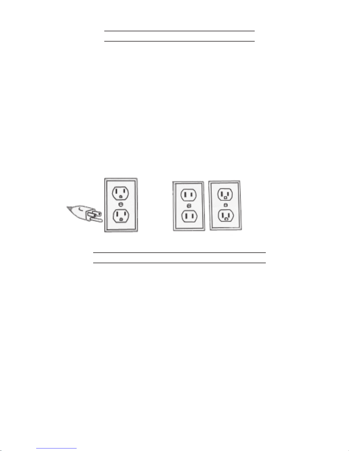
GROUNDING
WARNING!
Improperlyconnectingthe groundingwirecan resultin theriskofelectricshock.
Check with a qualified electrician if you are in doubt as to whether the outlet is
properly grounded.Do not modify the power cord plug provided with the tool or
product.Never remove the grounding prong from the plug.Do not use the tool if
the power cord or plug is damaged. If damaged, have it repaired by a service
facility before use.If the plug will not fit the outlet,have a proper outlet installed
by a qualified electrician.

Page 7
SKU 92509 For technical questions, please call 1-800-444-3353
GroundedTools withThree Prong Plugs
1. Tools marked with “Grounding Required” have a three wire cord and three prong
grounding plug. The plug must be connected to a properly grounded outlet.If the tool
should electrically malfunction or break down, grounding provides a low resistance
path to carry electricity away from the user, reducing the risk of electric shock. (See
Figure A.)
2. The grounding prong in the plug is connected through the green wire inside the cord
to the grounding system in the tool.The green wire in the cord must be the only wire
connected to the tool’s grounding system and must never be attached to an
electrically “live” terminal. (See Figure A.)
3. Your tool must be plugged into an appropriate outlet, properly installed and grounded
in accordance with all codes and ordinances. The plug and outlet should look like
those in the following illustration. (See Figure A.)
Double Insulated Tools with Two Prong Plugs
4. This product has a polarized plug (one blade is wider than the other) as a
feature to reduce the risk of electric shock.This plug will fit in a polarized outlet
only one way. If the plug does not fit fully in the outlet, reverse the plug. If it still does
not fit, contact a qualified electrician. Never use with an extension cord unless plug
can be fully inserted. Do not alter the plug.”
5. Tools marked “Double Insulated” do not require grounding.They have a special double
insulation system which satisfies OSHA requirements and complies with the
applicable standards of Underwriters Laboratories, Inc., the Canadian Standard
Association, and the National Electrical Code. (See Figure B above.)
6. Double insulated tools may be used in either of the 120 volt outlets shown in the
following illustration. (See Figure B above.)
Figure A Figure B

Page 8
SKU 92509 For technical questions, please call 1-800-444-3353
EXTENSION CORDS
1.
Grounded
tools require a three wire extension cord.
Double Insulated
tools can use
either a two or three wire extension cord.
2. As the distance from the supply outlet increases, you must use a heavier gauge
extension cord. Using extension cords with inadequately sized wire causes a serious
drop in voltage, resulting in loss of power and possible tool damage. (See Table A.)
3. The smaller the gauge number of the wire, the greater the capacity of the cord. For
example, a 14 gauge cord can carry a higher current than a 16 gauge cord. (See
Table A.)
4. When using more than one extension cord to make up the total length, make sure
each cord contains at least the minimum wire size required. (See Table A.)
5. If you are using one extension cord for more than one tool, add the nameplate
amperes and use the sum to determine the required minimum cord size. (See Table
A.)
6. If you are using an extension cord outdoors, make sure it is marked with the suffix “W-
A” (“W” in Canada) to indicate it is acceptable for outdoor use.
7. Make sure your extension cord is properly wired and in good electrical condition.
Always replace a damaged extension cord or have it repaired by a qualified electrician
before using it.
8. Protect your extension cords from sharp objects, excessive heat, and damp or wet
areas.
Table A
RECOMMENDED MINIMUM WIRE GAUGE FOR EXTENSION CORDS*
(120 VOLT)
NAMEPLATE
AMPERES
(At Full Load) EXTENSION CORD LENGTH
25
Feet 50
Feet 75
Feet 100
Feet 150
Feet
0 – 2.0 18 18 18 18 16
2.1 – 3.4 18 18 18 16 14
3.5 – 5.0 18 18 16 14 12
5.1 – 7.0 18 16 14 12 12
7.1 – 12.0 16 14 12 10 -
12.1 – 16.0 14 12 10 - -
16.1 – 20.0 12 10 - - -
* Based on limiting the line voltage drop to five volts at 150% of the rated amperes.

Page 9
SKU 92509 For technical questions, please call 1-800-444-3353
SYMBOLOGY
Table B
UNPACKING
When unpacking, check to make sure that all the parts are included.Refer to the Assembly
section, and the Assembly Drawing and Parts List at the end of this manual.
If any parts are missing or broken, please call Harbor Freight Tools at the number on the
cover of this manual as soon as possible.
OPERATING INSTRUCTIONS
Caution:Before cutting or trimming,run the tool for about 10 seconds to ensure that all
moving parts are running smoothly, and there are no loose parts, rattles, or sparking
that would indicate damage. Be sure the bit is firmly and properly installed before use.
Improperly installed bits may eject suddenly at high speed from the Router.
Controls and Indicators
On / Off Switch (6)
Handles (37)
Loosen to raise
or lower bit height
Ruler (44)
Base (54)
Knob (53) for Base
Angle Adjustment
Spindle Lock Button
Collet Nut (31)
Knob (40) - Unscrew
to remove Upper Ring (38)

Page 10
SKU 92509 For technical questions, please call 1-800-444-3353
Installing the Router Bit
1. Always unplug the Router Line Cord from the electrical outlet before making
adjustments and before installing bits.
2. Insert the Spanner Wrench (75) over the Collet Nut (31) and press in on the Spindle
Lock button to keep it from turning.
3. Loosen the Collet Nut (31) by turning it counterclockwise, but do not remove.
4. If there is already a bit in the Collet Cone, remove it.
It may be necessary to remove the Collect Nut to exchange the Collet Adapter for a
1/8” or 1/4” size, depending on the size of the bit shank. Replace the Collect Nut.
5. Make sure that the bit used is rated at more than 34,000 RPM. Push the shank end
of the new bit through the opening in the Collet Nut.There may be some resistance, so
make sure that it goes in all the way.
6. Press in on the Spindle Lock button, then tighten the Collet Nut (clockwise) with the
Spanner Wrench (75).
Adjusting Cutting Depth
You can set the depth of cut using the Ruler (44) scale on the side of the Router.
1. Install the router bit as previously described.
2. Loosen (counterclockwise) both Handles (37) securing the Ring (38) to the Guide
Poles (41). Slide the Ring (38) upward so the router bit is retracted within the Base.
3. Place the Base (54) on a flat surface and slide the Ring (38) down until the tip of the
bit contacts the flat surface.
The Ruler scale now shows the starting position.This starting position will vary,
depending on the bit used.
4. Add the desired depth of cut to the starting position. For example, if the starting
position is 1/4 inch, and the desired depth of cut is 1/2 inch, the correct adjustment on
the Ruler is 3/4 inch.
5. Raise the Ring (38) using the Handles (37) until the scale shows the correct reading.
Tighten both Handles (clockwise).You are now ready to cut.
Note: It is always wise to make a test cut to ensure that the Router is adjusted properly before
beginning to cut the final workpiece.
Spindle Lock button
Collet Nut (31)
Insert Router or Cutting Bit
Handles (37)
Loosentoraise
orlowerbit height Guide Poles (41)
Ring (38)
Base (54)

Page 11
SKU 92509 For technical questions, please call 1-800-444-3353
Using the Straight Guide
The Straight Guide is used to make cuts parallel to the edge of a workpiece, or following a
guide clamped onto the workpiece.
1. Assemble the Guide Plate Bracket (59) to the Guide Plate (58) using the Triangle
Knob (55). See photos below, and the Assembly Drawing.
2. Using two Screws (56), attach the Guide Plate (58) to the Base (54). Securely tighten
Screws.
3. Loosen Knob (55) and slide the (lower) Guide Plate Bracket (59) (in or out) to the
desired cut width as read on the Guide Plate (58) ruler.Tighten Knob (55). See
photos below-right.
4. After setting the desired distance from the router bit to the Guide Plate Bracket, turn
the Router over and double check the distance using a measuring tape. Readjust the
Guide Plate Bracket (59) if necessary.
5. Adjust the cutting depth as previously described on page 10.
6. Secure the workpiece to the work bench so that the clamps do not interfere with the
horizontal movement of the Router. Never hold the workpiece by hand.
7. Align the Guide Plate Bracket (59) to the edge of a test scrap workpiece, then lift the
Router slightly so that the bit is not touching the workpiece.Turn the On/Off Switch to
the On position.When at full speed, slowly lower the Router so the bit makes contact
with the workpiece to begin cutting parallel to the edge.
8. Make the cut parallel to the edge of the final workpiece with the Guide Plate Bracket
(59) following the edge.
9. When the cut is complete, lift the Router up and away from the workpiece. Flip the
Switch to the Off position.Wait for the bit to stop turning before setting the unit down.
Guide Plate
Bracket (59)
Guide Plate (58) Screw (56)
Ruler Knob
(55)

Page 12
SKU 92509 For technical questions, please call 1-800-444-3353
Using the Circle Guide
The Circle Guide enables cutting circles between 2-3/4 and 8-1/2 inches.
1. Assemble the Circle Guide components by placing the Plastic Rotary Ring, Upper (67)
through the top of the Lower Steel Hoop Ring (68) and Circle Arm (69), and screw into
the Plastic Rotary Ring, Lower (70). Refer to the Assembly Drawing.
2. Attach theTriangle Knob (71) through the Circle Arm (69) using Square Nut (72).
3. Attach the Handle (73) through the Circle Arm using Square Nut (74).
4. Using Triangle Knob (66), attach the Lower Steel Hoop Ring (68) to the Steel Housing
Ring (61).
5. Remove the Upper Plastic Hoop Ring (38) assembly from the Motor Housing by
unscrewing the Triangle Knob (40), pressing in on the Spindle Lock Button, then
sliding the Ring assembly off the Motor Housing.
6. Mount the Steel Housing Ring (61) to the Motor Housing as shown below. Secure in
place using Triangle Knob (40).
7. Install a cutter bit as described on page 10. Do not use router bits with the Circle
Guide.
8. Adjust the cutting depth of the bit by looseningTriangle Knob (66), then sliding the
Lower Steel Hoop Ring (68) up or down, exposing more or less of the bit. Retighten
Knob (66).
9. Set the circle radius by loosening the Triangle Knob (71), then sliding it to the desired
inch marker on the ruler of the Circle Arm (69). Retighten Knob (71).
10. Turn the Router over to measure and verify the distance between the bit and the
Triangle Knob (71) pointer (the circle radius).
11. Place the pointer of Triangle Knob (71) on the countersunk hole in the workpiece to
be cut.
12. Place one hand on the Handle (73), and the other on the Handle (60).
13. Flip the On/Off Switch (6) to the On position.When the Motor reaches full speed,
begin to turn the Router using both Handles, pivoting on the Triangle Knob pointer.
14. When the cut is complete, lift the Router up and away from the workpiece. Flip the
Switch to the Off position.Wait for the bit to stop turning before setting the unit down.
Triangle
Knob (71)
Handle (73)
CircleArm (69)
Triangle
Knob (40)
Triangle Knob (66)
Steel Hoop Ring, Lower (68)
Circle Arm (69)
Plastic Rotary Ring (70)
Lower
Handle (60)
Spindle Lock Button
Plastic Rotary Ring (67)
Upper (
hidden
)

Page 13
SKU 92509 For technical questions, please call 1-800-444-3353
Cutting Holes Freehand
1. Assemble the components of the Circle Guide as described on the previous page,
steps 1 through 7, with this exception: leave off the Circle Arm (69).
2. Install a cutting bit as described on page 10.
3. Adjust the bit depth to only 1/8 inch deeper than the material being cut (i.e., drywall).
When cutting drywall that is already mounted on the wall joists, be certain that the
circuit current to the wires in the wall are shut off at the circuit breaker.
4. Start the cut in the center of the area, at a slight angle when entering the material,
then level out the cutter. Move the cutter to the trim line and cut counterclockwise.
Best Trimming Routing Direction
The Router Bit rotates clockwise.You must adjust for this while cutting.
1. For most materials it is best to move the Router from left to right as you face the
workpiece.
2. When cutting outside edges, move the router counterclockwise.When cutting inside
edges, move the router clockwise.
INSPECTION, MAINTENANCE, AND CLEANING
WARNING! Make sure the Power Switch of the Router is in its “OFF” position and
that the tool is unplugged from its electrical outlet before performing any inspection,
maintenance, or cleaning procedures.
1. Before each use, inspect the general condition of the Router. Check for loose
screws, misalignment or binding of moving parts, cracked or broken parts, damaged
electrical wiring, and any other condition that may affect its safe operation. If
abnormal noise or vibration occurs, have the problem corrected before further use. Do
not use damaged equipment.
2. Periodically recheck all nuts, bolts, and screws for tightness.
3. Store in a clean and dry location.
4. Wipe the Tool with a clean cloth after every use.
5. After each use, blow out the Motor vent holes with compressed air to prevent the
buildup of dust and particles.
6. Periodically wipe the Collet, Collet Adapters, and Cutting Bits with a light oil to prevent
rust.
7. Over time, if the performance of the tool diminishes, or it stops working completely, it
may be necessary to replace the Carbon Brushes (10) by removing the Carbon Brush
Cover (11). This procedure must be completed by a qualified technician. If the
Carbon Brushes are not worn down, try cleaning the Carbon Brush tips with an ink
eraser.

Page 14
SKU 92509 For technical questions, please call 1-800-444-3353
PLEASE READTHE FOLLOWING CAREFULLY
THE MANUFACTURER AND/OR DISTRIBUTOR HAS PROVIDED THE PARTS DIAGRAM INTHIS
MANUAL AS A REFERENCETOOL ONLY. NEITHERTHE MANUFACTURER NOR DISTRIBUTOR
MAKES ANY REPRESENTATION OR WARRANTY OF ANY KIND TO THE BUYER THAT HE OR
SHEISQUALIFIEDTOMAKEANYREPAIRSTOTHEPRODUCTORTHATHEORSHEISQUALIFIED
TO REPLACE ANY PARTS OF THE PRODUCT. IN FACT, THE MANUFACTURER AND/OR
DISTRIBUTOREXPRESSLYSTATESTHATALLREPAIRSANDPARTSREPLACEMENTSSHOULD
BEUNDERTAKENBYCERTIFIEDANDLICENSEDTECHNICIANSANDNOTBYTHEBUYER.THE
BUYER ASSUMES ALL RISK AND LIABILITY ARISING OUT OF HIS OR HER REPAIRS TO THE
ORIGINAL PRODUCT OR REPLACEMENT PARTSTHERETO, OR ARISING OUT OF HIS OR HER
INSTALLATION OF REPLACEMENT PARTSTHERETO.
PARTS LIST
Part # Description Part # Description
1. Cable 39. Guide, Plastic Sleeve
2. Screw, Self-tapping 40. Knob, Triangle
3. Cover, Back 41. Guide Pole
4. Nut 42. Nut
5. Cable Sleeve 43. Ring, Plastic Hoop, Lower
6. Switch 44. Ruler, Steel
7. Inductor 45. Washer, Plain
8. Capacitor 46. Washer, Spring
9. Carbon Brush Holder 47. Screw
10. Carbon Brush 48. Washer, Plain
11. Cover, Carbon Brush 49. Washer, Spring
12. Cable Pressboard 50. Screw
13. Screw, Self-tapping 51. Nut
14. Housing 52. Angle Stop
15. Label 53. Knob, Triangle
16. Stator 54. Base
17. Screw, Self-tapping 55. Knob, Triangle
18. Bearing 56. Screw
19. Motor 57. Washer, Spring
20. Screw 58. Guide Plate
21. Washer, Spring 59. Bracket, Guide Plate
22. Cover, Bearing 60. Handle, Side A
23. Bearing 61. Ring, Steel Housing
24. Cover, Head 62. Handle, Side B
25. Screw, Self-tapping 63. Screw, Self-tapping
26. Pin, Self-locking 64. Screw, Self-tapping
27. Spring 65. Knob, Triangle
28. Ring, Shaft Retainer 66. Knob, Triangle
29. Nut, Axle Locking 67. Ring, Plastic Rotary, Upper
30. Collet 68. Ring, Steel Hoop, Lower
31. Nut, Collet 69. Arm, Circle
32. Ring, Shaft Retainer 70. Ring, Plastic Rotary, Lower
33. Screw, Self-tapping 71. Knob, Triangle, with Pointer
34. Guide, Plastic Sleeve 72. Nut, Square
35. Guide Pole, Inner Lining 73. Handle
36. Nut 74. Nut, Square
37. Handle 75. Wrench, Spanner
38. Ring, Plastic Hoop, Upper

Page 15
SKU 92509 For technical questions, please call 1-800-444-3353
NOTE:Some parts arelistedandshownforillustrationpurposesonly
and are not available individually as replacement parts.
ASSEMBLY DRAWING
Table of contents