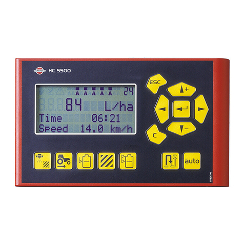
Hardi ISOBUS VT User manual

The Sprayer
Operator’s Manual
CONTROLLER
ISOBUS VT
Instruction book - SW 3.XX
67023603 - Version 1.10
US - 06.2015


CONTROLLER
ISOBUS VT
Instruction book - SW 3.XX
67023603 - Version 1.10
US - 06.2015
HARDI® reserves the right to make changes in design, material, or specification without notice thereof.
HARDI® and other product names are registered trademarks of HARDI® Inc. in the U.S. and in other countries.


Table of contents
TOC.1
1 - Welcome
Welcome letter ......................................................................................................................................1
2 - Safety notes
Operator safety .....................................................................................................................................1
Symbols ........................................................................................................................................................................................................................ 1
Precautions ................................................................................................................................................................................................................ 1
3 - Description
Introduction ..........................................................................................................................................1
About the ISOBUS VT system ......................................................................................................................................................................... 1
System description ................................................................................................................................2
Overall description ................................................................................................................................................................................................ 2
Terminals and boxes ..............................................................................................................................3
Types of terminals .................................................................................................................................................................................................. 3
ISOBUS Terminal layout ...................................................................................................................................................................................... 4
Soft keys menu tree .............................................................................................................................................................................................. 6
SetBox ............................................................................................................................................................................................................................ 7
HC 6300 Grip ............................................................................................................................................................................................................. 8
General keystrokes ................................................................................................................................................................................................ 8
Extended menu ................................................................................................................................................................................................... 10
Functions .............................................................................................................................................11
Auto functions general info .......................................................................................................................................................................... 11
End nozzles (Fence line) (optional) .......................................................................................................................................................... 11
DynamicFluid4 pressure regulation ........................................................................................................................................................ 12
SafeTrack (Trailed sprayers only) ................................................................................................................................................................ 14
HARDI® AutoSectionControl (optional) ................................................................................................................................................. 14
Menus ..................................................................................................................................................15
Full menu structure ........................................................................................................................................................................................... 15
4 - System setup
Tractor installation ................................................................................................................................1
Installation of control unit brackets ............................................................................................................................................................ 1
Printer ............................................................................................................................................................................................................................ 1
Speed transducer for sprayer ......................................................................................................................................................................... 2
How to set clock ..................................................................................................................................................................................................... 2
Initial settings ........................................................................................................................................3
System start-up ....................................................................................................................................................................................................... 3
Display readout ....................................................................................................................................................................................................... 3
ESC key for ISOBUS terminals ......................................................................................................................................................................... 3
Working in the field ...............................................................................................................................4
Set up before spray job ...................................................................................................................................................................................... 4
Volume rate ............................................................................................................................................................................................................... 5
Register readout and selection ..................................................................................................................................................................... 6
Tank contents ........................................................................................................................................................................................................... 6
TWIN Preset ................................................................................................................................................................................................................ 7
Spraying with DynamicFluid4 pressure regulation .......................................................................................................................... 7
Spraying with FlexCapacity pump .............................................................................................................................................................. 8
5 - Menu 1 Daily settings
Menu 1 Daily settings ............................................................................................................................1
Menu 1.1 Volume rate ......................................................................................................................................................................................... 1
Menu 1.2 Tank contents .................................................................................................................................................................................... 1
Menu 1.3 Select register .................................................................................................................................................................................... 1

Table of contents
TOC.2
6 - Menu 2 Setup
Menu 2 Setup .........................................................................................................................................1
General info ............................................................................................................................................................................................................... 1
Menu 2.1 Display readout ................................................................................................................................................................................. 1
Menu 2.2 Auto functions ................................................................................................................................................................................... 2
Menu 2.3 Variable Rate Application (VRA) / Remote / HARDI® AutoSectionControl ................................................... 3
Menu 2.4 Set clock ................................................................................................................................................................................................ 3
Menu 2.5 Alarms ..................................................................................................................................................................................................... 3
7 - Menu 3 Calibration
Menu 3 Calibration ................................................................................................................................1
Menu 3.1 Speed calibration ............................................................................................................................................................................. 1
Menu 3.2 Flow calibration ................................................................................................................................................................................ 3
Menu 3.3 Boom ....................................................................................................................................................................................................... 6
Menu 3.4 Regulation user setup ................................................................................................................................................................... 8
Menu 3.5 Tank gauge ....................................................................................................................................................................................... 11
Menu 3.6 Track ...................................................................................................................................................................................................... 14
8 - Menu 4 Toolbox
Menu 4 Toolbox .....................................................................................................................................1
Menu 4.1 Measure ................................................................................................................................................................................................. 1
Menu 4.2 Service intervals ................................................................................................................................................................................ 1
Menu 4.3 Service interval reset ...................................................................................................................................................................... 1
Menu 4.4 Reserved ................................................................................................................................................................................................ 1
Menu 4.5 Test ........................................................................................................................................................................................................... 2
Menu 4.6 Speed simulation ............................................................................................................................................................................. 2
Menu 4.7 Emergency ........................................................................................................................................................................................... 3
Menu 4.8 Computer CAN status ................................................................................................................................................................... 3
9 - Menu 5 Logbook
Menu 5 Logbook ....................................................................................................................................1
Menu 5.1 Print .......................................................................................................................................................................................................... 1
Menu 5.2 Data dump ........................................................................................................................................................................................... 2
10 - Maintenance
Off-season storage ................................................................................................................................1
Storage ......................................................................................................................................................................................................................... 1
11 - Fault finding
Operational problems ...........................................................................................................................1
Fault finding the system .................................................................................................................................................................................... 1
Checks for clogging .............................................................................................................................................................................................. 2
Checks for external leak ..................................................................................................................................................................................... 2
Location of components (trailed sprayers) ............................................................................................................................................ 3
Location of components (self-propelled sprayers) ........................................................................................................................... 4
Fault codes ................................................................................................................................................................................................................. 5
Emergency operation ..........................................................................................................................15
In an emergency situation ............................................................................................................................................................................ 15
Operation when a sensor fails ..................................................................................................................................................................... 15
12 - Testing and fine tuning
Testing and fine tuning .........................................................................................................................1
Fine tuning the flow constant - PPU .......................................................................................................................................................... 1
Pin & Wire connection ........................................................................................................................................................................................ 1
Testing flow transducer ..................................................................................................................................................................................... 2
Testing speed transducer ................................................................................................................................................................................. 2

Table of contents
TOC.3
13 - Technical specifications
Specifications ........................................................................................................................................1
Specifications ............................................................................................................................................................................................................ 1
Flow ranges for the flow transducers ........................................................................................................................................................ 1
Electrical connections ............................................................................................................................2
Types of plugs and fuses ................................................................................................................................................................................... 2
Materials and recycling .........................................................................................................................3
Disposal of electronics ........................................................................................................................................................................................ 3
Packaging information ....................................................................................................................................................................................... 3
Charts ....................................................................................................................................................4
Chart for recording values ................................................................................................................................................................................ 4
14 - Warranty
Warranty policy and conditions ............................................................................................................1

Table of contents
TOC.4

1.1
1 - Welcome
Welcome letter
Dear New HARDI® Owner,
Thank you for purchasing your new HARDI® product and welcome to the ever-increasing family of proud HARDI® owners.
HARDI® is the leading sprayer company in offering growers strong, reliable products made for the widest range of
applications worldwide. Quality, reliability, and resale value make the HARDI® product line the preferred product line of
customers both in North America as well as worldwide. Our guiding principle is to provide the highest level of customer
satisfaction and long term value in the marketplace today. We have developed a very high level of customer loyalty in the
marketplace which we are very proud of and strive every day to maintain and to continue to grow.
HARDI® is your specialist in spraying and we spend all of our time and keep all of our focus on spraying. We do not share our
resources between other types of products or compromise on anything in providing the best quality sprayers to the market
today. We can provide the latest in technology with our products if desired, or allow them to operate with the technology
that you already use on other products in most cases. You get to decide that, and what best suits your needs. We feel that
you, our customer, are the best suited to answer that question for your operation. Either way, you decide, and we will try and
help make it happen for you.
Our broad spectrum of product offerings, from the ruggedly simple models we build to our highly sophisticated models,
the built-in HARDI® strength and reliability ensures a low cost of ownership. HARDI® sprayers are all based on a functional
design concept of being as simple to operate as possible and to meet our customers’ requirements for all their application
needs.
Please take the time to thoroughly read the Operator’s Manual before using your equipment. You will find many helpful hints
as well as important safety and operation information.
Some of the features on your HARDI® sprayer were suggested by growers. There is no substitute for “on farm”experience
and we invite your comments and suggestions. If any portion of this instruction book remains unclear after reading it,
contact your HARDI® dealer or service personnel for further explanation before using the equipment.
For Product, Service or Warranty Information please contact your local HARDI® dealer.
- Please use the HARDI® Customer Service number: 1-866-770-7063
- Or send your email to CUSTSERV@hardi-us.com
HARDI® NORTH AMERICA INC.
Visit us online at: www.hardi-us.com
1500 West 76th St.
Davenport, Iowa 52806
Phone: (563) 386-1730
Fax: (563) 386-1280
Sincerely,
Wayne Buchberger
President

1 - Welcome
1.2

2.1
2 - Safety notes
Operator safety
Symbols
These symbols are used throughout the book to designate where the reader needs to pay extra attention.
€This symbol means DANGER. Be very alert as your safety is involved!
±This symbol means WARNING. Be alert as your safety can be involved!
This symbol means ATTENTION. This guides to better, easier and safer operation of your sprayer!
÷This symbol means NOTE.
Precautions
Note the following recommended precautions and safe operating practices before using the sprayer.
General info
€Read and understand this instruction book before using the equipment. It is equally important that other operators
of this equipment read and understand this book.
€If any portion of this instruction book remains unclear after reading it, contact your HARDI® dealer for further
explanation before using the equipment.
€Keep children away from the equipment.
€Press the keys with the underside of your finger. Avoid using your fingernail.
€Local law may demand that the operator is certified to use spray equipment. Adhere to the law.
€Tractor driver’s seat is the intended working place during operation.
Service
€Test with clean water prior to filling with chemicals. Rinse and wash equipment after use and before servicing.
€Never service or repair the equipment while it is operating. Always replace all safety devices or shields immediately
after servicing.
€Turn electrical power off before connecting and disconnecting the display and transducers, servicing or using a
battery charger.
€If an arc welder is used on the equipment or anything connected to the equipment, disconnect power leads before
welding. Remove all flammable or explosive material from the area.
€Do not use a high pressure cleaner to clean the electronic components.

2 - Safety notes
2.2

3.1
3 - Description
Introduction
About the ISOBUS VT system
The ISOBUS VT is for use in agricultural and horticultural production. The components are developed to last many years
under agricultural conditions.
The system has a non-volatile memory without battery which simplifies storage. All parameters in the menus are saved in
the memory and are not lost when the power is disconnected.
The transducers utilized are chosen for long service life and good signal quality. The speed and flow transducers have a built-
in diode that will flash to indicate when it’s functioning, to aid servicing.
Optional transducers include pressure and revolutions readout. Other options include a 12 Volt printer.
Working pictures will be shown in different colors, depending on the function used.
Display readouts
Among many possible display readouts, are:
•Volume rate.
•Speed.
•Liquid rate per minute.
•Total covered area.
•Total volume sprayed.
•99 trip registers. It includes a total register that summarizes data from the 98 trip registers.
The system is also compatible with Variable Rate Application (VRA) and is prepared for communication with Precision
Farming tools (e.g. HARDI® AutoSectionControl). Data dump of registers and configuration to a personal computer
are possible.
Functions include
•Correct area with closure of up to 13 spray boom sections.
•Many alarm functions and possibility for audio/visual alarm etc.
•Many warnings depending on operation. Alarms and warnings is shown in the bottom left 1/4 corner of the display
on some VT screens. HC 9500 will show alarms in top of the screen.
Main components Location
ISOBUS terminal Tractor/Self-propelled
HC 6300 Grip Tractor/Self-propelled
HC 6400 SetBox/Spray Center Tractor/Self-propelled
HC 6100 JobCom Sprayer/Self-propelled
HC 6200 FluidBox/Outside Box Sprayer/Self-propelled

3 - Description
3.2
System description
Overall description
The precise wiring setup can vary, depending on the terminal mounted.
ISOBUS system (trailed)
ISOBUS system (self-propelled)
A. HC 9500 or VT Terminal.
B. SetBox and Grip.
C. GPS antenna (optional).
D. IBBC connector.
E. Vehicle bus.
F. ISOBUS.
G. FluidBox (i-sprayers only).
H. JobCom (Implement ECU).
I. Center section junction box.
J. Hydraulics block.
K. AutoHeight UC5.
L. ISOBUS bridge.
M. Cabin connector.

3 - Description
3.3
Terminals and boxes
Types of terminals
This software can run with two types of ISOBUS display terminals.
ISOBUS terminals with physical buttons
ISO terminals with physical function buttons, e.g. the Massey Ferguson
terminal shown.
•Conventional or touch screen and physical buttons.
•Function buttons are graphical but are operated by physical
buttons on the terminal.
•The software runs as a Virtual Terminal (VT) into the terminal
software.
ISOBUS terminals with touchscreen interface
HARDI® HC 9500 or similar ISO terminals with touchscreen interface. The
HC 9500 is shown.
•Touchscreen and no buttons (except ON/OFF).
•Function buttons are graphical and operated by pressing the
touch screen.
•The software runs as a Virtual Terminal (VT) into the terminal
software.

3 - Description
3.4
ISOBUS Terminal layout
The ISOBUS terminal layout is described as follows:
ISOBUS virtual terminal buttons
1. Scroll up, increase a value or volume rate.
2. Enter menu.
3. Scroll down, decrease a value or volume rate.
4. Preset keys.
5. Soft menus.
6. Escape a menu.
7. Scroll up.
8. Enter menu or confirm a value.
9. Scroll down.

3 - Description
3.5
Display symbols
These symbols are common on VT (Virtual Terminal) displays.
1. The 1st Line is for status symbols, register number and alarm
number. All status symbols will be displayed here.
ATTENTION! If an error occurs, alarm/warning error number will
be shown instead of register number. The alarm/warning
number can be recognized by the exclamation sign in front of the
number.
2. The 2nd Line is for boom status, foam marker and end nozzle
indications.
3. ISOBUS: The bottom half has 6 boxes with selectable information.
÷NOTE! See “Menu 2.1 Display readout” on page 6.1 for setup of
the display readouts in the bottom half of the terminal display.
1st line status icons
All “OK” Information Warning Stop (critical) Over or under
application
Volume rate
Automatic
Variable rate (GPS)
active
Volume rate Manual Pendulum Locked Pendulum
Unlocked
Track Crab left Track Crab right Track Lock Track Automatic Track Manual
Options A on Options B on Options both on Options both off
TWIN Preset 1 TWIN Preset 2 TWIN Manual
Auto mode
Nozzle size
calculated
Auto mode
No flow to sections
Auto mode
Nozzle size not
calculated
Manual mode
Nozzle size
calculated
Manual mode
No flow to sections
Manual mode
Nozzle size not
calculated
Increment steps
mode
Nozzle size
calculated
Increment steps
mode
No flow to sections
Increment steps
mode
Nozzle size not
calculated

3 - Description
3.6
A. Preset keys
Vital information while spraying is quick and easy
to access.
Pressing the button will enter a submenu with the
preset keys.
B. Soft keys
Soft keys control optional features. Press the soft
key button to activate a submenu with further
features.
ATTENTION! The number of levels in the soft
key menu system depends on the number
of functions - see also “Soft keys menu tree”
below.
C. Navigation keys
The navigation keys are initially used for set up in the menu system by coding in values. The navigation keys can change the
volume rate in a set percentage or fixed volume rate. Other keys appear as needed on the ISOBUS Terminal.
D. Numeric keys
The keys will be the standard numeric keypad for the specific ISOBUS terminal.
Soft keys menu tree
ISOBUS Description
This key appears whenever necessary at respective menus, etc.
See “ESC key for ISOBUS terminals” on page 6.1 for setup of this
button.
Used to escape back to previous screen.
This key appears whenever necessary at respective menus, etc. Used to scroll up.
This key appears whenever necessary at respective menus, etc. Used to enter a menu or confirm a value.
This key appears whenever necessary at respective menus, etc. Used to scroll down.
This is normally a key in the standard numeric keypad of the specific
terminal.
Used to clear a value or register.
LEVEL 1 LEVEL 2 LEVEL 3 LEVEL 4
ICON FUNCTION ICON FUNCTION ICON FUNCTION
F1 EndNozzles F1 Left ON Work screen
F2 Left OFF
F3 Right OFF Work screen
F4 Right OFF

3 - Description
3.7
SetBox
The SetBox controls secondary functions. The keys are grouped into control areas to simplify operator understanding.
÷NOTE! Self-propelled sprayers do not have a SetBox as the controls are built-in to the cabin.
1. Power ON/OFF.
2. Pendulum unlock.
3. Pendulum lock.
4. Inner wing fold.
5. Inner wing unfold.
6. 1st outer wing fold.
7. 1st outer wing unfold.
8. 2nd outer wing fold.
9. 2nd outer wing unfold.
10. Automatic volume rate selector.
11. Manual pressure control.
12. Foam marker regulation.
13. Foam marker Left/Right selector.
14. DynamicCenter adjustment (increments).
15. DynamicCenter outer positions 1 or 5.
16. Optional function A-B.
17. HeadlandAssist automatic.
18. HeadlandAssist boom align.
19. SafeTrack manual control (if installed).
20. SafeTrack align selector (if installed).
21. SafeTrack automatic selector (if installed).
ATTENTION! Button 1 has different function on ISOBUS sprayers as this turns the JobCom ON/OFF.
ATTENTION! Buttons 17 and 18 can have different functions if the sprayer is equipped with AutoHeight.
ATTENTION! The Grip cannot be switched ON/OFF separately. It is automatically switched ON when tractor power is
turned ON (ISOBUS).

3 - Description
3.8
HC 6300 Grip
The Grip is an ergonomic remote unit that can be easily mounted inside
the tractor cabin. All common functions required during normal
spraying can be operated with the Grip. Also the Grip controls some
optional functions.
ATTENTION! The Grip cannot be switched ON/OFF separately. It is
automatically switched ON when tractor power is turned ON
(ISOBUS).
A. Status LED.
B. Boom section controls (up to 13).
C. Main ON/OFF.
D. Tilt.
E. Boom height.
F. Boom slant.
G. Not used.
H. TWIN presets.
General keystrokes
The first steps to choose a menu are shown below. See also “Full menu structure” on page 3.15.
Menu selection
1. Press {Menu} Virtual Terminal button to proceed into the menu.
2. Navigate to desired submenu using arrows.
3. In the menu, the current selection is marked with a colored bar.
4. Move the menu colored bar up and down by using the {up} and
{down} arrows.
÷NOTE! A maroon colored bar indicates current setting.
5. Confirm selection by pressing the enter arrow.
ATTENTION! Press {ESC} to leave the menu without changing values.
÷NOTE! There is help text for each menu in the bottom of the display. The displayed help text corresponds to the
location of the colored bar on the Virtual Terminal.
Table of contents
Other Hardi Controllers manuals

Hardi
Hardi HC 9600 User manual

Hardi
Hardi HC5500 User manual
Hardi
Hardi HC5500 User manual

Hardi
Hardi HC5500 User manual
Hardi
Hardi HC 5500 SPRAY BOX III User manual
Hardi
Hardi HC 8500 User manual

Hardi
Hardi HC 6500 User manual

Hardi
Hardi HC5500 User manual
Hardi
Hardi HC 6500 User manual

Hardi
Hardi HC5500 User manual
Popular Controllers manuals by other brands
Power Electronics
Power Electronics VS65 Series Hardware and installation manual

Bürkert
Bürkert TopControl ON/OFF operating instructions
Cisco
Cisco Catalyst C9800-L Hardware installation guide

ASG
ASG ASG-SD2500 user guide

AGS
AGS Merlin 1000S Installation, operation and maintenance guide
Emerson
Emerson AMPGARD RVSS Instruction booklet
