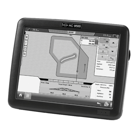
Hardi HC5500 User manual

CONTROLLER
HC5500
Original
Instruction book - SW 4.XX
67000400-201 - Version 2.01
GB - 10.2008
www.hardi-international.com

We congratulate you for choosing a HARDI plant protection product. The reliability and ef-
ficiency of this product depend upon your care. The first step is to carefully read and pay
attention to this instruction book. It contains essential information for the efficient use and
long life of this quality product.
The original instruction book is approved and published in English. All other languages are translations of the
original. In the event of any conflicts, inaccuracies or deviations between the English original and other languages
the English version shall prevail.
Illustrations, technical information and data in this book are to the best of our belief correct at the time of printing.
As it is HARDI INTERNATIONAL A/S policy permanently to improve our products, we reserve the right to make
changes in design, features, accessories, specifications and maintenance instructions at any time and without
notice.
HARDI INTERNATIONAL A/S is without any obligation in relation to implements purchased before or after such
changes.
HARDI INTERNATIONAL A/S cannot undertake any responsibility for possible omissions or inaccuracies in this
publication, although everything possible has been done to make it complete and correct.
.As this instruction book covers more models and features or equipment, which are available in certain countries
only, please pay attention to paragraphs dealing with precisely your model.
Published and printed by HARDI INTERNATIONAL A/S

3
Table of Contents
1 - CE Declaration
Declaration of conformity .....................................................................................................................7
2 - Safety notes
Operator safety .....................................................................................................................................9
General info ............................................................................................................................................................................................................... 9
3 - Description
General info .........................................................................................................................................11
General info ............................................................................................................................................................................................................ 11
Glossary and pictorial symbols ................................................................................................................................................................... 12
HARDI LookAhead .............................................................................................................................................................................................. 12
Pressure based regulation (optional equipment) ........................................................................................................................... 13
SafeTrack and IntelliTrack ............................................................................................................................................................................... 13
System description ..............................................................................................................................14
Overall description ............................................................................................................................................................................................. 14
Keys .....................................................................................................................................................15
General key description .................................................................................................................................................................................. 15
General keystrokes, Example: Tank contents ..................................................................................................................................... 17
Keystroke menu tree ......................................................................................................................................................................................... 18
4 - System setup
Tractor installation ..............................................................................................................................19
Control units .......................................................................................................................................................................................................... 19
Installation of control unit brackets ......................................................................................................................................................... 19
Power supply ......................................................................................................................................................................................................... 20
Printer ......................................................................................................................................................................................................................... 20
Speed transducer for sprayer ...................................................................................................................................................................... 20
Speed transducer for tractor ........................................................................................................................................................................ 21
Foot pedal remote ON/OFF (optional) .................................................................................................................................................. 21
Initial system start-up ....................................................................................................................................................................................... 22
Screen contrast adjustment ......................................................................................................................................................................... 22
Daily settings .......................................................................................................................................23
System start-up .................................................................................................................................................................................................... 23
LookAhead nozzle choice .............................................................................................................................................................................. 23
Check LookAhead pressure regulation at speed change .......................................................................................................... 24
Check LookAhead pressure regulation at section change ....................................................................................................... 25
Pressure based regulation (optional equipment) ........................................................................................................................... 25
Menu 1.1 Volume rate .........................................................................................................................27
How to change the volume rate ............................................................................................................................................................... 27
5 - Menu 1 Daily settings
Menu 1.2 Tank contents ......................................................................................................................28
To change the displayed Tank contents .............................................................................................................................................. 28
Menu 1.3 Select register ......................................................................................................................29
Menu 1.3.1 Register readout and selection ........................................................................................................................................ 29
6 - Menu 2 Setup
Menu 2.1 Display readout ...................................................................................................................31
General info ............................................................................................................................................................................................................ 31
Menu 2.1.5 Work rate ........................................................................................................................................................................................ 31
Menu 2.2 Auto functions .....................................................................................................................32
Menu 2.2.1 Main ON/OFF ............................................................................................................................................................................... 32
Menu 2.2.2 Foam Marker (optional) ........................................................................................................................................................ 32
Menu 2.2.3 Dual line (optional) .................................................................................................................................................................. 32
Menu 2.3 VRA/Remote control ............................................................................................................33
Variable Rate Application (VRA) / Remote / HARDI AutoSectionControl ......................................................................... 33
Menu 2.4 Set clock ...............................................................................................................................34
How to set clock .................................................................................................................................................................................................. 34

Table of Contents
4
Menu 2.5 Alarms ..................................................................................................................................35
How to set up alarms ........................................................................................................................................................................................ 35
Menu 2.5.6 Audio level .................................................................................................................................................................................... 35
Menu 2.6 Register names ....................................................................................................................36
How to name the registers ........................................................................................................................................................................... 36
Menu 2.6.XX Copy name ................................................................................................................................................................................ 36
7 - Menu 3 Calibration
Menu 3.1 Speed calibration .................................................................................................................37
Menu 3.1.1 Sprayer ............................................................................................................................................................................................. 37
Menu 3.1.1.1 Constant ..................................................................................................................................................................................... 38
Menu 3.1.1.2.1 Practical ................................................................................................................................................................................... 38
Menu 3.2 Flow calibration ...................................................................................................................39
Which method to use ...................................................................................................................................................................................... 39
Menu 3.2.2 Nozzle method ........................................................................................................................................................................... 40
Menu 3.2.3 Tank method ............................................................................................................................................................................... 40
Menu 3.2.4 Circulation ..................................................................................................................................................................................... 41
Menu 3.3 Boom ....................................................................................................................................42
Menu 3.3.1 Width ................................................................................................................................................................................................ 42
Menu 3.3.2 Number of sections ................................................................................................................................................................. 42
Menu 3.3.3 Nozzles/section .......................................................................................................................................................................... 42
Menu 3.3.4 End nozzles (optional) ........................................................................................................................................................... 42
Menu 3.4 Regulation constant .............................................................................................................43
Regulation constant .......................................................................................................................................................................................... 43
Menu 3.5 Tank gauge ..........................................................................................................................44
General info ............................................................................................................................................................................................................ 44
Menu 3.5.1 Adjustment ................................................................................................................................................................................... 44
Menu 3.5.2 Total ................................................................................................................................................................................................... 45
Menu 3.6 Track ....................................................................................................................................47
General info ............................................................................................................................................................................................................ 47
Track ............................................................................................................................................................................................................................ 47
Reversing the sprayer ....................................................................................................................................................................................... 47
Menu 3.6.1 Track width ................................................................................................................................................................................... 48
Menu 3.6.2 Tractor drawbar ......................................................................................................................................................................... 48
Menu 3.6.3 Dead zone ..................................................................................................................................................................................... 48
Menu 3.6.4 Damping ....................................................................................................................................................................................... 48
Menu 3.6.5 Alignment offset ....................................................................................................................................................................... 49
Menu 3.6.6 Sensitivity ...................................................................................................................................................................................... 49
Emergency Track ................................................................................................................................................................................................. 50
Menu 3.7 LookAhead ...........................................................................................................................51
Menu 3.7.X LookAhead calibration ......................................................................................................................................................... 51
8 - Menu 4 Toolbox
Menu 4.1 Measure ...............................................................................................................................53
Trip meter ................................................................................................................................................................................................................ 53
Menu 4.2 Service intervals ..................................................................................................................54
Menu and intervals ............................................................................................................................................................................................ 54
Service interval reset ......................................................................................................................................................................................... 54
Menu 4.3 Stop watch ...........................................................................................................................55
Use as timer ............................................................................................................................................................................................................ 55
Menu 4.4 Alarm clock ..........................................................................................................................56
How to use alarm ................................................................................................................................................................................................ 56
Menu 4.5 Test ......................................................................................................................................57
How to test .............................................................................................................................................................................................................. 57
Menu 4.6 Speed simulation .................................................................................................................58
How to use speed simulation ..................................................................................................................................................................... 58
Menu 4.7 Emergency Track ..................................................................................................................59
Menu 4.7 Emergency Track .......................................................................................................................................................................... 59

Table of Contents
5
9 - Menu 5 Logbook
Menu 5.1 Print .....................................................................................................................................61
What you can print ............................................................................................................................................................................................ 61
Menu 5.2 Data dump ...........................................................................................................................62
How to dump data ............................................................................................................................................................................................. 62
10 - Mistblowers
Soft keys ..............................................................................................................................................63
General info ............................................................................................................................................................................................................ 63
Unit Canopy Row ................................................................................................................................................................................................ 63
How to control canopy ................................................................................................................................................................................... 63
Fixed read out of canopy measures ........................................................................................................................................................ 64
Menu 3.3.2 Number of sections ................................................................................................................................................................. 64
Menu 3.3.3 Section size ................................................................................................................................................................................... 64
11 - Maintenance
Off-season storage ..............................................................................................................................65
Storage ...................................................................................................................................................................................................................... 65
12 - Fault finding
Emergency operation ..........................................................................................................................67
In an emergency situation ............................................................................................................................................................................ 67
Operational problems .........................................................................................................................68
Operational faults ................................................................................................................................................................................................ 68
Mechanical faults ................................................................................................................................................................................................ 69
13 - Testing and fine tuning
Testing and fine tuning .......................................................................................................................71
Fine tuning the flow constant - PPU ....................................................................................................................................................... 71
Testing flow transducer .................................................................................................................................................................................. 72
Testing speed transducer .............................................................................................................................................................................. 72
14 - Technical specifications
Specifications ......................................................................................................................................73
Specifications ......................................................................................................................................................................................................... 73
Flow ranges for the flow transducers ..................................................................................................................................................... 73
Baud rate .................................................................................................................................................................................................................. 73
Materials and recycling .......................................................................................................................74
Disposal of electronics ..................................................................................................................................................................................... 74
Packaging information .................................................................................................................................................................................... 74
Charts ..................................................................................................................................................75
Chart for recording values ............................................................................................................................................................................. 75
Index
Index ....................................................................................................................................................77

Table of Contents
6

7
1 - CE Declaration
Declaration of conformity
declare that the following product;
A. was manufactured in conformity with the provisions in the COUNCIL DIRECTIVE of 22 June 1998 on mutual
approximation of the laws of Member States on the safety of machines (98/37/EEC) with special reference to Annex 1
of the Directive on essential health and safety requirements in relation to the construction and manufacture of
machines.
B. was manufactured in conformity with the provisions in other relevant COUNCIL DIRECTIVES.
C. was manufactured in conformity with the current standards implementing harmonised standards in accordance with
Article 5 (2) and other relevant standards.
Taastrup, 04. 2016
Lars Nejsum
Vice President, Product Development
HARDI INTERNATIONAL A/S
Manufacturer: Importer:
HARDI INTERNATIONAL A/S
Helgeshøj Allé 38
DK 2630 Taastrup
DENMARK
Model no.
Serial no.

1 - CE Declaration
8

9
2 - Safety notes
Operator safety
€This symbol means DANGER. Be very alert as your safety is involved!
±This symbol means WARNING. Be alert as your safety can be involved!
μThis symbol means ATTENTION. This guides to better, easier and more safe operation of your sprayer!
÷This symbol means NOTE.
General info
€Note the following recommended precautions and safe operating practices.
€Read and understand this instruction book before using the equipment. It is equally important that other operators
of this equipment read and understand this book.
€Keep children away from the equipment.
€If any portion of this instruction book remains unclear after reading it, contact your HARDI dealer for further
explanation before using the equipment.
€Turn electrical power off before connecting and disconnecting the display and transducers, servicing or using a
battery charger.
€If an arc welder is used on the equipment or anything connected to the equipment, disconnect power leads before
welding.
€Test with clean water prior to filling with chemicals.
€Do not use a high pressure cleaner to clean the electronic components
€Press the keys with the underside of your finger. Avoid using your fingernail.

2 - Safety notes
10

11
3 - Description
General info
General info
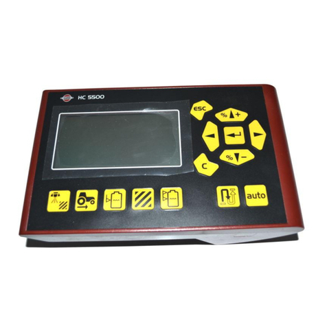
The HARDI Controller 5500 is for use in agricultural and horticultural production. The Controller permits automatic control
of application rate.
Main components are:
•Controller
•Spray Box
•Junction box (on sprayer)
•Jobcomputer (for SafeTrack and AutoSectionControl functions)
•Flow transducer (on sprayer)
•Speed transducer (on sprayer or tractor)
The Controller has a four line display permitting much information to be shown at the same time. Display readout includes
volume rate, speed, liquid rate per minute, total covered area, total volume sprayed and 99 trip registers. It includes a total
register that summarizes data from the 98 trip registers. It is illuminated internally so readout is possible even for night-time
work.
If used on a mistblower, volume applied can also be set up as “Unit Canopy Row”. Tree width and height can be changed on
the go.
Functions include correct area with closure of up to 9 spray boom sections, alarm functions for volume rate, minimum tank
contents, speed min./max. and possibility for audio/visual alarm.
The Spray Box has integrated controls for the spray functions, foam marker, end nozzles and optional electric valves.
The transducers utilised are chosen for long service life and good signal quality. The speed and flow transducer has a diode
built into the housing to aid servicing. As the wheel or rotor turns, the diode will flash thereby indicating it function correctly.
The Controller is also compatible for Variable Rate Application and is prepared for communication with Precision Farming
tools.
Data dump of registers and configuration to a personal computer is possible.
The system has a non-volatile memory with no battery which simplifies storage. All parameters in the menus are saved in
the Controllers memory and are not lost when the power is disconnected.
The controller have been developed to last many years under agricultural conditions.
Optional transducers include pressure, revolutions, area meter and tank gauge. Other options include a 12 Volt printer and
a foot operated remote ON/OFF for the Main ON/OFF.

3 - Description
12
Glossary and pictorial symbols
Text shown in the shaded rectangular windows are what will be seen on
the Controller display when pressing bottons as described in the
explanations. An example on display read-out are shown to the right.
HARDI LookAhead
With LookAhead, the pressure regulation valve can predict the correct setting before the main switch goes to ON. It
improves application precision, also when re-starting after a tank fill.
LookAhead helps farmers who have tractors with semiautomatic gearbox, meaning the“hardimatic”function does not work
due to constant PTO revs.
The LookAhead system has 3 main features:
1. To improve regulation response time when sections are shut OFF or opened.
2. To improve regulation response time when the spraying speed changes during headland turns.
3. To stabilise regulation during pressure/flow fluctuations in the period immediately after main ON/OFF function is
turned ON.
The LookAhead feature is active when the boom is unfolded and the LookAhead menu is activated and calibrated.
When the power is switched to ON, note the regulation valve will adjust from the actual setting to the minimum setting and
then back again to determine its actual position.
For LookAhead to function correctly the controller must know which nozzles and application rate will be used. This is
selected from a number of nozzle choices stored in memory. At start up of the controller, it will promt user for a choice
between using nozzles used at last spray job or select a new nozzle to be used.
μATTENTION! The tractor gearbox must be an automatic or semi-automatic type with constant revolutions P.T.O. or the
tractor must be driven with constant R.P.M. for the LookAhead to work properly.
Controller HARDI Controller 5500 with display.
Spray Box HARDI Control Box with all basic control functions.
Junction box Box on the sprayer for Controller and Control Box.
Jobcom Box on the sprayer with SafeTrack computer and/or AutoSectionControl.
Transducer Device that transforms variations to a signal. Also called a sensor.
[ abc ] Text shown on the Controller display.
[ X ] or [ Y ] Variable figures.
PPU Pulses per unit. For speed and flow calibration, the unit measure is metre and litre respectively.
EVC Electric Valve Control unit. Designates an equal pressure liquid system.
EFC Electric Fast Control unit. Designates a no equal pressure system.
VRA Variable Rate Application (often refered to “GPS”).
UCR Unit Canopy Row, an application unit used on mistblowers.
MAINMENU
Dailysettings
1

3 - Description
13
Pressure based regulation (optional equipment)
To improve the non-equal systems EFC and PrimeFlow an optional sensor can be mounted to switch from flow to pressure
based regulation. When active, the system automatically switches to pressure based regulation when the flow drops below
the minimum flow rate for the flowmeter.
The drop of flow can be due to number of sections selected for the boom and number of nozzles in each section. If there
are few or only one nozzle in the last section of the boom and the sprayer is spraying in an angle and only the last section
is open there is almost no flow in the liquid system, resulting it to close down.
Same will happen if the sprayer is fitted with a large flow house. The flowmeter will stop rotating and measure no flow with
small boom sections or nozzles with low output.
SafeTrack and IntelliTrack
SafeTrack and IntelliTrack are a steering mechanism for the HARDI sprayers. When using a track system, sprayer stability is a
common concern. Many factors influence the sprayer and conditions where the sprayer might tip over have to be dealt with.
The factors that the driver can influence with are:
•Driving behaviour
•Field conditions
•Tyre width
•Tyre pressure
Read sprayers instruction book for further information.
If unsafe driving occurs an alarm will be triggered, and the sprayer will align. Be aware that the alarm can not be turned off
as long as unsafe driving still occurs! (See paragraph “Menu 3.6 Track”)
μATTENTION! If necessary the level of security can be adjusted - please contact your local HARDI dealer.
€DANGER!The system has been calibrated during driving on flat fields. Special attention should be made when driving
in hilly conditions.
€DANGER! When driving on fields with deep tracks, then the speed must be decreased.

3 - Description
14
System description
Overall description
1. Controller
2. Spray Box
3. To 12 Volt power supply
4. Multi wire plug and cable
5. Junction box (on sprayer)
6. Jobcom (optional)
7. Flow transducer
8. Speed transducer
9. Tank contents transducer (optional)
10. Printer (optional)
11. Harness for tractor speed/area switch/foot remote ON/OFF

3 - Description
15
Keys
General key description
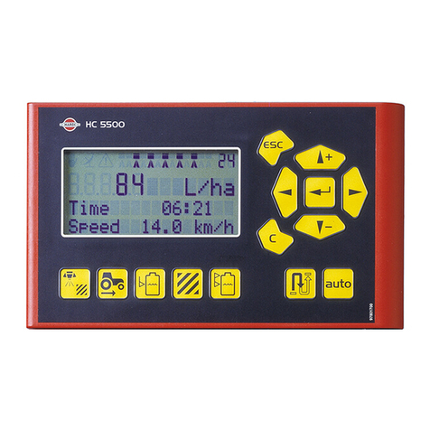
The HC 5500 controller buttons are placed in three groups; navigation
keys, shortcut keys, distance key and the auto key.
The shortcut keys can be used for the following:
:
Short press: Displays volume sprayed for the active register.
Long press: Enter Register select (menu 1.3.1 Register select).
:
Short press : Displays the actual speed.
Long press: Enter Speed calibration (menu 3.1.1 Speed).
Short press: Displays the actual tank contents.
Long press: Enter Tank contents menu (menu 1.2 Tank contents).
:
Short press: Show Area covered for active register.
Long press: Enter Register select (menu 1.3.1 Register select).
:
Short press: Show the selected volume rate.
Long press: Enter Volume rate menu (menu 1.1 Volume rate).
Short press: Shows remaining spraying distance with actual tank contents.
Long press: Enter Measure distance menu (menu 4.1.1 Distance).
Pressing will: Enable Autofunction.
%

3 - Description
16
The navigation keys are initially used for set up in the menu system and working screen.
To navigate the menus then press to start this process. Then bottons can be used for the following:
Pressing will:
•Scroll up,
•Increase an value.
Pressing will:
•Scroll down,
•Decrease a value.
Pressing will:
•Move the cursor to the left.
Pressing will:
•Move the cursor to the right.
Pressing will:
•Escape a menu (hold to escape all menus),
•Escape without changing a value.
Pressing will:
•Clear a value,
•Reset the active register (hold until countdown is finished).
Pressing will:
•Enter a menu,
•Confirm (accept) a value.
When having the working screen then the navigation keys can be used for the following:
Pressing will:
•Increase volume rate in steps or select another preset application rate.
Pressing will:
•Decrease volume rate in steps or select another preset application rate.
Pressing will:
•Reset the active register (hold until countdown is finished).
Pressing will:
•Enter a menu.

3 - Description
17
General keystrokes, Example: Tank contents
The following is a general description in keystrokes and display readout. The following example, of changing the Tank
contents value, is used to illustrate this. Try it! The same method is used in all the menus.
μATTENTION! When a menu is open, the blinking number or value is the one that can be altered.
Press to enter the menu system [1 MAIN MENU].
The 2nd line will show the menu number.
The 3rd line will read the present menu.
The 4th line will show a choice.
÷Note the menu number [1] is blinking.
Press to enter menu [1.1 Daily settings].
Press or to scroll to [1.2 Tank contents].
÷NOTE! The last digit of the menu number [1.2] is blinking.
Press to enter [1.2 TANK CONTENTS].
÷NOTE! The value that can be changed is blinking.
Press or to move the cursor.
Press or to set the desired value.
Press to confirm.
Press and hold, to exit the menu system.
1
MAINMENU
Dailysettings
1.2
DAILYSETTINGS
Tankcontents
1.2
TANKCONTENTS XXXXL

3 - Description
18
Keystroke menu tree
The first steps to choose a menu are shown below.
Press to proceed into the menu. See the relevant section in the book.
Press and hold to exit the menu system.
5 Logbook 5.2 Data dump
5.1 Print
4 Toolbox 4.7 Emergency track
4.6 Speed simulation
4.5 Test
4.4 Alarm clock
4.3 Stop watch
4.2 Service intervals
4.1 Measure
3 Calibration 3.7 LookAhead
3.6 Track
3.5 Tank gauge
3.4 Regulation constant
3.3 Boom
3.2 Flow
3.1 Speed
2 Setup 2.6 Register names
2.5 Alarms
2.4 Set clock
2.3 GPS/Remote
2.2 AUTO functions
2.1 Display readout
Main menu
1 Daily settings 1.3 Select register
1.2 Tank contents
1.1 Volume rate

19
4 - System setup
Tractor installation
Control units
Find a suitable place in the tractor’s cabin to secure the control units
from movement. Best recommended placement is to the right of the
driver seat. The supplied bracket will fit most tractors. Threaded
mounting holes may be hidden behind front corner cover.
Installation of control unit brackets
The supplied tractor pillar bracket (A) has a hole spacing of 100 and 120
mm. Check tractor instructions manual for information regarding
attachment points.
Three tubes (B) are supplied. One, two or all 3 may be used. They can be
bent and shortened. A spacer (C) is also supplied to allow further
attachment possibilities. Find the best solution for your tractor or
vehicle.
Tube (B) plate is staggered so if correctly orientated, all boxes will line up.
The recommended setup is to place the spacer (C) between the two
tubes (B) used for the controllers and the 3rd tube (B) which is to be
mounted in the bracket (A), as shown on the picture.
μATTENTION! An extension cable is available as an option if the HC
5500 control unit is to be placed further away from the EFC
control unit. (Ref. no. 261933)
100 -120mm
A
B
C

4 - System setup
20
Power supply
The power requirement is 12-15 Volt DC. Always note polarity!
Brown wire is positive (+)
Blue wire is negative (-).
Power supply must come directly from the battery. For proper function
of the electric equipment, the wires must have the following
recommended cross sectional areas and correct fuses to ensure a
sufficient power supply. The delivered power connectors follows the
standard of most newer tractors. If having a tractor with another power
connector it is necessary to disassemble connector and fit it to the actual tractor connector.
Use the HARDI Electric distribution box (Ref. no. 817925) if the tractor has a doubtful wiring.
±WARNING! Do not connect to the starter motor or generator/alternator. Warranty is void if this is done.
μATTENTION! See paragraph “System start-up” for more about connecting the controller.
Printer
If the 12 Volt printer is fitted, the supplied tube can be utilised to fit the printer on the Controller/Terminal brackets.
μATTENTION! The Controller/Terminal should be protected from moisture and should be removed when not in use, if
the tractor does not have a cabin.
Speed transducer for sprayer
The speed transducer is located at the inside of the sprayers right wheel.
It is an inductive type that requires a metallic protrusion to pass by it to
trigger a signal. To trigger a speed ring is used. It should be adjusted so
transducer is placed to the centre of the holes in the speed ring (vertical
direction). Recommended distance between protrusion and transducer
(A) is 3 to 6 mm. Check this in the whole circumference. Correct fitting is
indicated by constant blinking from transducer when the wheel rotates.
CIGAR CONNECTOR
Spray control unit requires:
Wire 2.5 mm, Fuse 10 Amp
Hydraulic control unit requires:
Wire 4.0 mm, Fuse 16 Amp
JOBCOM CONNECTOR
The unit requires:
Wire 6.0 mm, Fuse 25 Amp
Other manuals for HC5500
6
Table of contents
Other Hardi Controllers manuals
Hardi
Hardi HC5500 User manual
Hardi
Hardi HC 8500 User manual

Hardi
Hardi HC5500 User manual
Hardi
Hardi COMMANDER 5500 User manual

Hardi
Hardi HC5500 User manual

Hardi
Hardi HC 2500 Series User manual
Hardi
Hardi HC 5500 SPRAY BOX III User manual

Hardi
Hardi HC5500 User manual

Hardi
Hardi HC5500 User manual

Hardi
Hardi HC 6500 User manual
Popular Controllers manuals by other brands
Fortinet
Fortinet FortiController-5103B Session-Aware Load Balancer Guide

SOLAREG II
SOLAREG II Energy HE Installation and operating instructions

Sound Devices
Sound Devices CL-6 user guide

THOMSON
THOMSON TSC 80 - V2.2 Service manual
Lenze
Lenze L-force CS Series operating instructions
Honeywell
Honeywell RP920A-D Service data
