Hardi HC 5500 SPRAY BOX III User manual

CONTROLLER HC 5500
SPRAY BOX III
Original
Instruction book - SW 5.XX
67000400-301 - Version 3.01
GB - 12.2014
www.hardi-international.com

We congratulate you for choosing a HARDI plant protection product. The reliability and ef-
ficiency of this product depend upon your care. The first step is to carefully read and pay
attention to this instruction book. It contains essential information for the efficient use and
long life of this quality product.
The original instruction book is approved and published in English. All other languages are translations of the
original. In the event of any conflicts, inaccuracies or deviations between the English original and other languages
the English version shall prevail.
Illustrations, technical information and data in this book are to the best of our belief correct at the time of printing.
As it is HARDI INTERNATIONAL A/S policy permanently to improve our products, we reserve the right to make
changes in design, features, accessories, specifications and maintenance instructions at any time and without
notice.
HARDI INTERNATIONAL A/S is without any obligation in relation to implements purchased before or after such
changes.
HARDI INTERNATIONAL A/S cannot undertake any responsibility for possible omissions or inaccuracies in this
publication, although everything possible has been done to make it complete and correct.
As this instruction book covers more models and features or equipment, which are available in certain countries
only, please pay attention to paragraphs dealing with precisely your model.
Published and printed by HARDI INTERNATIONAL A/S

3
Table of Contents
1 - EC Declaration
EC Declaration of conformity .................................................................................................................7
2 - Safety notes
Operator safety .....................................................................................................................................9
Symbols ........................................................................................................................................................................................................................ 9
General Info ............................................................................................................................................................................................................... 9
3 - Description
General info .........................................................................................................................................11
Controller features .............................................................................................................................................................................................. 11
Glossary and pictorial symbols ................................................................................................................................................................... 12
System description ..............................................................................................................................13
Main components .............................................................................................................................................................................................. 13
DynamicFluid4 pressure regulation ........................................................................................................................................................ 14
Keys and Display .................................................................................................................................15
General description of controller keys ................................................................................................................................................... 15
General description of display .................................................................................................................................................................... 17
General description of switches for Spray Box III ............................................................................................................................ 18
General keystrokes, example ....................................................................................................................................................................... 19
Options control on Spray Box III, example .......................................................................................................................................... 20
Menu tree ................................................................................................................................................................................................................ 21
4 - System setup
Tractor installation ..............................................................................................................................23
Control units .......................................................................................................................................................................................................... 23
Installation of control unit brackets ......................................................................................................................................................... 23
Power supply ......................................................................................................................................................................................................... 24
Printer ......................................................................................................................................................................................................................... 24
Speed sensor for the sprayer ....................................................................................................................................................................... 25
Speed sensor for the tractor ......................................................................................................................................................................... 25
Footswitch remote ............................................................................................................................................................................................. 26
Initial system start-up ....................................................................................................................................................................................... 26
Screen contrast adjustment ......................................................................................................................................................................... 26
Daily settings .......................................................................................................................................27
System start-up .................................................................................................................................................................................................... 27
5 - Menu 1, Daily Settings
Menu 1.1 Volume rate .........................................................................................................................29
How to change the volume rate ............................................................................................................................................................... 29
How to read the preset volume rate ...................................................................................................................................................... 30
How to use manual dosage ......................................................................................................................................................................... 30
Menu 1.2 Tank contents ......................................................................................................................31
How to change the tank contents ........................................................................................................................................................... 31
Menu 1.3 Select register ......................................................................................................................32
How to select a register and its data ....................................................................................................................................................... 32

Table of Contents
4
6 - Menu 2, Setup
Menu 2.1 Display Readout ...................................................................................................................33
General info ............................................................................................................................................................................................................ 33
Example of readout ........................................................................................................................................................................................... 33
Menu 2.1.1 Program : Actual ........................................................................................................................................................................ 33
Menu 2.1.2 Flow rate ......................................................................................................................................................................................... 33
Menu 2.1.3 Optional sensor .......................................................................................................................................................................... 34
Menu 2.1.4 Time .................................................................................................................................................................................................. 34
Menu 2.1.5 Work rate ........................................................................................................................................................................................ 34
Menu 2.1.6 Volume rate .................................................................................................................................................................................. 34
Menu 2.1.7 Tank contents .............................................................................................................................................................................. 34
Menu 2.1.8 Speed ............................................................................................................................................................................................... 35
Menu 2.1.9 Volume : Area .............................................................................................................................................................................. 35
Menu 2.1.10 Active boom size .................................................................................................................................................................... 35
Menu 2.2 Auto Functions .....................................................................................................................36
Menu 2.2.1 Auto ON/OFF ............................................................................................................................................................................... 36
Menu 2.2.2 Foam marker (optional) ........................................................................................................................................................ 36
Menu 2.3 VRA/Remote .........................................................................................................................37
VRA / Remote Control/ AutoSectionControl ..................................................................................................................................... 37
Menu 2.4 Set Clock ..............................................................................................................................38
How to set clock .................................................................................................................................................................................................. 38
Menu 2.5 Alarms ..................................................................................................................................39
How to set up alarms ........................................................................................................................................................................................ 39
Menu 2.5.1 Volume rate .................................................................................................................................................................................. 39
Menu 2.5.2 Tank contents .............................................................................................................................................................................. 39
Menu 2.5.3 Spray pressure ............................................................................................................................................................................ 39
Menu 2.5.4 Fan speed ...................................................................................................................................................................................... 40
Menu 2.5.5 Speed ............................................................................................................................................................................................... 40
Menu 2.5.6 Audio level .................................................................................................................................................................................... 40
Menu 2.5.7 Sections off ................................................................................................................................................................................... 41
Menu 2.6 Register Names ....................................................................................................................42
How to name the registers ........................................................................................................................................................................... 42
Menu 2.6.XX Copy name? .............................................................................................................................................................................. 42
7 - Menu 3, Calibration
Menu 3.1 Speed calibration .................................................................................................................43
Menu 3.1.1 Sprayer ............................................................................................................................................................................................. 43
Menu 3.1.1.1 Constant ..................................................................................................................................................................................... 44
Menu 3.1.1.2. Practical ...................................................................................................................................................................................... 44
Menu 3.2 Flow calibration ...................................................................................................................45
Which method to use ...................................................................................................................................................................................... 45
Menu 3.2.2 Nozzle method ........................................................................................................................................................................... 46
Menu 3.2.3 Tank method ............................................................................................................................................................................... 47
Menu 3.3 Boom ....................................................................................................................................48
Menu 3.3.1 Width ................................................................................................................................................................................................ 48
Menu 3.3.2 Number of sections ................................................................................................................................................................. 48
Menu 3.3.3 Nozzles/section .......................................................................................................................................................................... 48
Menu 3.3.4 End nozzles ................................................................................................................................................................................... 48
Menu 3.4 Regulation constant .............................................................................................................49
General info ............................................................................................................................................................................................................ 49
Menu 3.4.1 Flow sensor restriction .......................................................................................................................................................... 49
Menu 3.4.2 Simulated speed value .......................................................................................................................................................... 50
Menu 3.4.3 Nozzle size flow at 3 bar ....................................................................................................................................................... 51
Menu 3.4.4 Reserved ......................................................................................................................................................................................... 51
Menu 3.4.5 Type of nozzle ............................................................................................................................................................................. 51
Menu 3.4.6 Regulation parameter ............................................................................................................................................................ 52

Table of Contents
5
Menu 3.5 Tank gauge ..........................................................................................................................53
General info ............................................................................................................................................................................................................ 53
Menu 3.5.1 Adjustment ................................................................................................................................................................................... 53
Menu 3.5.2 Calibration ..................................................................................................................................................................................... 54
Menu 3.5.3 Tank selection ............................................................................................................................................................................. 55
Menu 3.5.4 Offset empty ................................................................................................................................................................................ 55
8 - Menu 4, Toolbox
Menu 4.1 Measure ...............................................................................................................................57
Tripmeter .................................................................................................................................................................................................................. 57
Menu 4.2 Service interval ....................................................................................................................58
Menus and intervals .......................................................................................................................................................................................... 58
Service interval reset ......................................................................................................................................................................................... 58
Menu 4.3 Stopwatch ............................................................................................................................59
Use as timer ............................................................................................................................................................................................................ 59
Menu 4.4 Alarm clock ..........................................................................................................................60
How to use the alarm clock .......................................................................................................................................................................... 60
Menu 4.5 Test ......................................................................................................................................61
How to make equipment test ..................................................................................................................................................................... 61
Menu 4.6 Speed simulation .................................................................................................................63
How to use speed simulation ..................................................................................................................................................................... 63
9 - Menu 5, Logbook
Menu 5.1 Print .....................................................................................................................................65
What you can print ............................................................................................................................................................................................ 65
Menu 5.2 Data dump ...........................................................................................................................66
How to dump data ............................................................................................................................................................................................. 66
10 - Maintenance
Off-season maintenance ......................................................................................................................67
Off-season storage ............................................................................................................................................................................................. 67
11 - Fault finding
Emergency Operation ..........................................................................................................................69
In an emergency situation ............................................................................................................................................................................ 69
Operational Problems .........................................................................................................................70
Operational faults ................................................................................................................................................................................................ 70
Mechanical faults ................................................................................................................................................................................................ 70
Operation when a sensor fails ..................................................................................................................................................................... 71
Fluid system test .................................................................................................................................................................................................. 72
Alarm list ................................................................................................................................................................................................................... 73
12 - Testing and fine tuning
Testing and fine tuning .......................................................................................................................75
Fine tuning the flow constant - PPU ....................................................................................................................................................... 75
Testing flow sensor ............................................................................................................................................................................................ 76
Testing speed sensor ........................................................................................................................................................................................ 76
13 - Technical specifications
Specifications ......................................................................................................................................77
Electrical properties ........................................................................................................................................................................................... 77
Flow ranges for flow sensors ....................................................................................................................................................................... 77
Baud rate .................................................................................................................................................................................................................. 77
Materials and Recycling .......................................................................................................................78
Disposal of electronics ..................................................................................................................................................................................... 78
Packaging information .................................................................................................................................................................................... 78
Notes ....................................................................................................................................................79
Table for recording values ............................................................................................................................................................................. 79
Index
Index ....................................................................................................................................................81

Table of Contents
6

7
1 - EC Declaration
EC Declaration of conformity
declare that the following product (information is to be filled out at the Pre-Delivery Inspection (PDI);
A. was manufactured in conformity with the provisions in the COUNCIL DIRECTIVE of 22 June 1998 on mutual
approximation of the laws of Member States on the safety of machines (98/37/EEC) with special reference to Annex 1
of the Directive on essential health and safety requirements in relation to the construction and manufacture of
machines.
B. was manufactured in conformity with the provisions in other relevant COUNCIL DIRECTIVES.
C. was manufactured in conformity with the current standards implementing harmonised standards in accordance with
Article 5 (2) and other relevant standards.
Taastrup, 09. 2014
Henning Jørgensen
Vice President, Product Development
HARDI INTERNATIONAL A/S
Manufacturer: Importer:
HARDI INTERNATIONAL A/S
Helgeshøj Allé 38
DK 2630 Taastrup
DENMARK
Model no.
Serial no.

1 - EC Declaration
8

9
2 - Safety notes
Operator safety
Symbols
These symbols are used thorough the book to designate where some sort of extra attention has to paid for the reader. The
four symbols have following meaning.
±This symbol means WARNING. Be alert as your safety can be involved!
μThis symbol means ATTENTION. This guides to better, easier and more safe operation of your sprayer!
÷This symbol means NOTE. Extra information is provided.
General Info
Note the following recommended precautions and safe operating practices.
€Read and understand this instruction book before using the equipment. It is equally important that other operators
of this equipment read and understand this book.
€Keep children away from the equipment.
€Turn electrical power off before connecting and disconnecting the display and sensors, servicing or using a battery
charger.
€If an arc welder is used on the equipment or anything connected to the equipment, disconnect power leads before
welding.
±Do not use a high pressure cleaner to clean the electronic components.
μTest the sprayer with clean water prior to filling it with chemicals.
μPress the keys with the underside of your finger. Avoid using your fingernails.
μIf any portion of this instruction book remains unclear after reading it, contact your HARDI dealer for further
explanation before using the equipment.

2 - Safety notes
10

11
3 - Description
General info
Controller features
The HARDI Controller 5500 is for use in agricultural and horticultural production. The Controller permits automatic control
of application rate.
Main components are:
•Controller HC 5500
•Spray Box III
•Junction box for DF4 regulation
•Junction box on spray boom
•Sensor for spraying pressure (bar)
•Sensor for spray flow (litres/min)
•Sensor for sprayer’s ground speed (km/h)
•Sensor for pump speed (rpm)
•Sensor for regulation valve opening (degrees)
The Controller has a 4-line display permitting much information to be shown at the same time.
Display readout includes:
•Volume rate
•Speed
•Liquid rate per minute
•Total area sprayed
•Total volume sprayed
and 99 trip registers. It includes a total register (no. 99), which summarizes data from the 98 trip registers. It is illuminated
internally, so readout is possible even for night-time work.
Spray Box III has integrated controls for:
•Spray functions
•Foam marking
•End nozzles control
•Optional functions
The sensors used are chosen for long service life and good signal quality. The speed and flow sensors have a diode built into
the housing to aid servicing. As the wheel or rotor turns, the diode will flash, thereby indicating correct function.
The Controller is also compatible for Variable Rate Application (VRA), and it is prepared for communication with Precision
Farming tools.
Data dump of registers and configuration to a personal computer is possible.
The system has a non-volatile memory with no battery, which simplifies storage. All parameters in the menus are saved in
the Controller’s memory, and they are not lost, when the power is disconnected.
The Controller has been developed to last many years under agricultural conditions.
Optional sensor includes a tank gauge.
Other options include a 12-volt printer and a footswitch for the main ON/OFF (spraying ON/OFF).

3 - Description
12
Glossary and pictorial symbols
Text shown in the shaded rectangular windows are what will be seen on
the Controller display, when pressing buttons as described in the
explanations. An example on display readout are shown to the right.
Controller HARDI Controller 5500 with display and pushbuttons.
Spray Box III HARDI Control Box in the tractor with all basic control functions for the sprayer.
Junction box Box on the sprayer for Controller and Spray Box.
Sensor Device that transforms variations to a signal; also called a transducer.
[ abc ] Text shown on the Controller display.
[ X ] or [ Y ] Variable figures.
PPU Pulses per unit. For speed and flow calibration, the unit measure is meter and liter respectively.
EFC Electric Fast Control unit. Designates a no equal pressure system.
GPS Global Positioning System to be used for navigation.
VRA Variable Rate Application (often connected to the GPS system).
MAIN MENU
Daily settings
1

3 - Description
13
System description
Main components
1. Controller HC 5500
2. Spray Box III
3. To 12 volt power supply
4. Multi-wire plug and cable to sprayer
5. Printer *
6. Wire harness for tractor speed, area switch and footswitch ON/OFF *
7. Junction box for DF4 regulation
8. Junction box on spray boom
9. Sensor for spraying pressure (bar)
10. Sensor for spray flow (litres/min)
11. Sensor for sprayer’s ground speed (km/h)
12. Sensor for pump speed (rpm)
13. Sensor for regulation valve opening (degrees)
14. Sensor for tank contents (litres) *
* Optional equipment.
10
11
12
5
6
7
8
9
13 14

3 - Description
14
DynamicFluid4 pressure regulation
Traditional fluid regulation starts, when the nozzles are opened.
With DynamicFluid4 (DF4), the regulation is a continuous process, even if the nozzles are closed. Two ceramic (or plastic)
discs regulate the pressure and ensures quick reaction and zero leakages. Sprayer speed, PTO speed and number of spray
sections activated are parameters used, and the benefit is more precise application rates from the second the sprayer begins
spraying.
The DynamicFluid4 use feed forward technology based on 5 sensors, which feed the Spray Box III with data necessary for
optimal regulation. It auto-primes the spray boom at start-up and moves the regulation valve towards its final position
immediately after the operator makes changes. For example, when section valves are opened or closed, the regulation valve
is started at the same time as the section valve motors are started. This prevents overpressure situations e.g. after running
empty and refilling of main tank.
The 5 sensors are also back-up for each other and ensures that the system can continue regulation, even if one or more
sensor signals fails.
Sensors for DF4:
•Sprayer speed (km/h)
•Flow (l/min)
•Pressure (bar)
•Pump speed (rpm)
•Regulation valve opening angle (°)
The DynamicFluid4 pressure regulation features:
•Very fast and accurate regulation, when all sensors are working ok, setup in menus are correct and pump, filters and
valves are in good condition.
•Quick reacting valve, when sections are turned ON/OFF and at speed changes.
•Optimized for different PTO systems.
•Nozzle surveillance. No setup or tuning required for nozzle change.
•Warning in display, if failures occur on boom plumbing, such as severe clogging of line or nozzle filters or large leakages
on hoses and fittings.
•All functions work through with degraded performance (Limp-home modes), if:
Faults occur in fluid system, e.g. pump defects, clogged filters, leaking valves.
Sensor failure appear on pressure sensor, flow sensor or pump sensor.
There is a wrong setup of sprayer data in the menus.
•Emergency mode, if angle sensor or speed sensor fails.

3 - Description
15
Keys and Display
General description of controller keys
The controller keys are placed in three groups:
1. Navigation keys (to the right of display)
2. Shortcut keys (below display)
3. Distance key and auto key (bottom right corner)
Navigation keys
They are initially used for set up in the menu system and working screen.
To navigate the menus, press to start this process. The buttons can
be used for the following:
Press :
•Scroll up,
•Increase an value.
Press :
•Scroll down,
•Decrease a value.
Press :
•Move digit selection to the left.
Press :
•Move digit selection to the right.
Press :
•Escape a menu (hold button to escape all menus),
•Escape without changing a value.
Press :
•Clear a value,
•Reset the active register (hold until countdown of 5 seconds is finished).
Press :
•Enter a menu,
•Confirm (accept) a value.
When having the working screen, the navigation keys can then be used for the following:
Press :
•Increase volume rate in steps or select another preset application rate.
%

3 - Description
16
Press :
•Decrease volume rate in steps or select another preset application rate.
Press :
•Reset the active register (hold until countdown is finished).
Press :
•Enter a menu.
Short cut keys
You can either press the keys shortly or a little longer to display different functions.
The shortcut keys can be used for the following:
:
Short press: Displays volume rate sprayed for the active register.
Long press: Enter menu [1.1 VOLUME RATE] to set the desired volume rate.
:
Short press: Displays the actual driving speed.
Long press: Enter menu [3.1.1 SPEED] to calibrate a speed sensor.
Short press: Displays the actual tank contents.
Long press: Enter menu [1.2.1 TANK CONTENTS] to change the tank contents value.
:
Short press: Shows the area covered for the active register.
Long press: Enter menu [1.3.1 SELECT REGISTER] to select a register and view data.
:
Short press: Shows the spray volume used.
Long press: Enter menu [1.3.1 SELECT REGISTER] to select a register and view data.
Distance key
Short press: Shows remaining spraying distance with actual tank contents.
Long press: Enter menu [4.1.1 DISTANCE] to measure the distance being driven.
Auto key
Press the key to enable automatic spray function.

3 - Description
17
General description of display
There are four lines with symbols, numbers and text when looking at the working screen. The appearances of these items
at the screen depend on the controller settings and spray functions.
1st line
Manual adjustment of the spray pressure has been activated on the Spray Box.
Variable rate application (VRA) is enabled from an external source, e.g. a GPS system.
Warning.
Spray section = ON. Main ON/OFF switch = ON. Spraying is in progress.
Spray section = ON. Main ON/OFF switch = OFF. No spraying.
Spray section = OFF. Main ON/OFF switch = ON. No spraying in the section, which is turned turned OFF.
The symbol is flashing when the main ON/OFF switch is ON.
Register number.
2nd line
Current value as selected from the five shortcut buttons below the screen. Default value is spray output (litres/hectare).
3rd line
Spray parameter and current value as selected in the setup menu. Default value is spray pressure (bar).
4th line
Spray parameter and current value as selected in the setup menu. Default value is time of the day (hours:minutes).
1st line :
2nd line :
3rd line :
4th line :

3 - Description
18
General description of switches for Spray Box III
1. Power ON/OFF - This switch controls both the Spray Box and the Controller. When turned on, the lamp below the
switch will flash red three times, and hereafter it will be a constant green light. If a constant red light is shown, there is
a malfunction in the Spray Box, and you should contact HARDI for technical assistance.
2. Pressure regulation - Adjusting the spray pressure up or down manually. When this switch is activated, the hand
symbol appears in the top left corner of the controller display. To return to automatic pressure control, press the AUTO
key on the controller.
3. Main ON/OFF - Spraying is turned ON or OFF.
4. Options control - Select option A or B or none, depending on how the optional equipment (if any) is connected.
5. End nozzle control - Select left or right side for spraying boundaries of the field, if needed.
6. Foam marking - Select the frequency of foam markings on the ground. 1 = few markings, 10 = many markings.
7. Foam marking - Select left or right side for foam markings.
8. Boom section valves - Spraying ON/OFF for individual spray boom sections.
1
23
8
7
6
5
4

3 - Description
19
General keystrokes, example
The following is a general description in keystrokes and display readout on the controller. The following example, of
changing the tank contents value, is used to illustrate this. Try it! The same method is used in all the menus.
μATTENTION! The top line of symbols will stay shaded, unless the symbols are relevant. When a menu is open, the
flashing number or value is the one that can be altered.
Press to enter the menu system [1 MAIN MENU].
The 2nd line shows the menu number.
The 3rd line shows the present menu.
The 4th line shows a choice.
÷NOTE! The menu number [1] is flashing.
Press to enter menu [1.1 DAILY SETTINGS].
Press to scroll to menu [1.2 Tank].
÷NOTE! The last digit of the menu number [1.2] is flashing.
Press to enter menu [1.2.1 Tank contents].
÷NOTE! The value that can be changed is flashing.
Press or to move the select the digit.
Press or to set the desired value in litres.
Press to confirm.
Press and hold, to exit the menu system.
1
MAIN MENU
Daily settings
1.2
DAILY SETTINGS
Tank
1.2.1
TANK CONTENTS
XXXX L

3 - Description
20
Options control on Spray Box III, example
Optional equipment : Dilution kit
The control switch for optional equipment can be flicked left or right.
See the section “General description of switches for Spray Box III” to
locate the switch.
When the switch for operating the dilution kit is flicked to the left, the
display line 3 and 4 show this:
The tank contents are now being diluted.
The text is flashing - 3 seconds ON, 3 seconds OFF, until the dilution of
the tank is stopped.
When the switch for operating the dilution kit is flicked to the right, the
display line 3 and 4 show this:
The boom contents are now being diluted.
The text is flashing - 3 seconds ON, 3 seconds OFF, until the dilution of
the boom is stopped.
÷NOTE! Select the middle position for the switch for no dilution.
DILUTION
Tank
DILUTION
Boom
This manual suits for next models
1
Table of contents
Other Hardi Controllers manuals
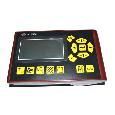
Hardi
Hardi HC5500 User manual

Hardi
Hardi HC 9600 User manual
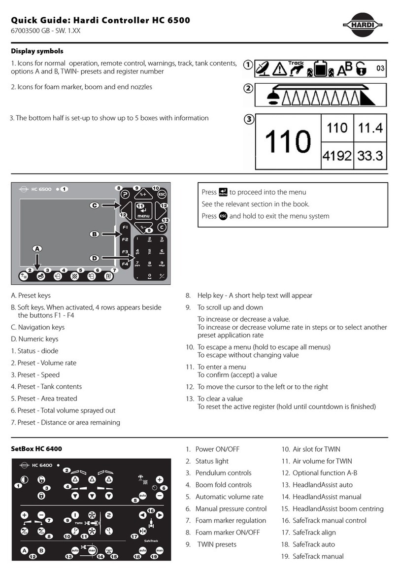
Hardi
Hardi HC 6500 User manual
Hardi
Hardi HC 6500 User manual

Hardi
Hardi HC5500 User manual
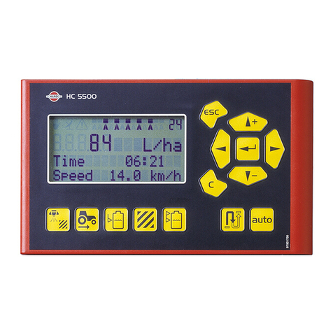
Hardi
Hardi COMMANDER 5500 User manual

Hardi
Hardi HC5500 User manual

Hardi
Hardi HC5500 User manual

Hardi
Hardi HC5500 User manual

Hardi
Hardi HC5500 User manual
Popular Controllers manuals by other brands
Allen-Bradley
Allen-Bradley Logix5000 Series Application book
Milesight
Milesight UC51 Series user guide

Eaton
Eaton SFX Series Installation and operation manual
ITT
ITT Engineered Valves Advantage 2.1 Maintenance manual
janitza
janitza Prophi 12R manual

Mitsubishi Electric
Mitsubishi Electric MELSEC LJ72GF15-T2-U-HW Safety Guidelines
