Harken Industrial R27 User manual

Read the manual carefully before using, installing and servicing the equipment.
Translation of the
original instructions
UR27R 20-03-2019
R27 Rail
Instruction Manual


20/03/19 ENGLISH 3
Contents
About this manual
Safety info
R27 Rail
Components
Prerequisites and limitations
Design
Preliminary info
Placing the rail
Coloured rail
Bent rail
Thermal expansion
Installation
Rail Installation Guidelines
End stop assembly instructions
Preliminary and periodical checks
Annual check
Packaging, storage, transportation
Maintenance
Certifications
Labeling
Warranty
Certificate of Compliance
Records
Correct installation form
Acceptance report
Esample of license plate
Maintenance-Inspection register
4
5
6
6
8
11
11
12
13
13
14
14
15
16
18
20
20
20
20
21
21
22
23
23
24
25
26
page
page
page
page
page
page
page
page
page
page
page
page
page
page
page
page
page
page
page
page
page
page
page
page
page
page
page

4 ENGLISH 20/03/19
ABOUT THIS MANUAL
Before installing or using the Harken R27 rail, read the instructions contained in this Manual thoroughly.
This instruction manual is an integral part of the product, and it supplies all the necessary information for its
correct installation, safe use and maintenance.
If you don’t understand some of the instructions, please contact Harken’s authorized dealer/installer. Harken
shall not be liable for damages, injuries or death caused by a non-compliance to the safety and other
instructions contained in this manual.
This manual is intended for qualified installers and users. The installer is responsible for integrating the
supplied information according to current legislations.
This manual, including the information supplied by the installer, must be stored by the client and made
available to the user. It must be stored in a suitable place, near the fail arrest system entrance, and it must be
made available to the user.
This manual may be modified without notice. See http://www.harkenindustrial.com for updated versions.
WARNING!
It is essential for the safety of the user that if the product is re-sold outside the original country
of destination the reseller shall provide instructions for use, for maintrnance, for periodic
examination and for repair in the language of the country in which the product is to be used.
ABOUT THIS MANUAL

20/03/19 ENGLISH 5
SAFETY INFO
•Harken R27 rail must be installed by personnel authorized by Harken or Harken dealer or by qualified
personnel trained on the installation of the Harken R27 rail, and on PPE (Personal Protective Equipment)
•The rail installer must make sure that the structure where the rail will be installed is suitable to fasten
the device and to support the loads for which the rail has been certified.
•The type of structure anchor/fixing must be defined by a qualified professional.
•The procedure to fasten the rail to the base must be documented in suitable reports, made available
for future consultation.
•Each rail has maximum load limits, which mostly depend on the structure where it is installed
and on the distance between the anchor/fixing; those limits must not be exceeded.
•The R27 rail must be used solely with Harken trolleys (IN9565, IN9565.CLEAR, IN9608, IN9608.CLEAR,
IN9606, IN9606.CLEAR, IN10614, IN10614.CLEAR, IN10615, IN10615.CLEAR, IN10567, IN10567.CLEAR),
wearing suitable PPE (Personal Protective Equipment) compliant with the laws in force
on workplace safety.
•Before using the rail, check its path and the falling hazards, evaluating the minimum fall clearance
and choosing the PPE with shock absorber deployment most suitable to the type of hazard.
•Before each use, check the system for any trace of wear, corrosion, deformation, loose connection, etc...
In case of doubts, if a rail seems unsafe, it must be checked by Harken or Harken dealer’s authorized
personnel or by qualified personnel.
•All operators using the rail must observe the instructions for uses, and especially the number of operators
it can support at the same time.
•In case of extreme weather events, do not use the rail
•In case of fire or if the rail has been struck by lightning, stop using it, report the issue to Harken Approved
Installer and/or Harken to arrange a detailed inspection by Approved and Qualified Personnel.
•Do not modify the rail in any way, unless previously authorized in writing by Harken or Harken dealer’s
authorized personnel or by qualified personnel.
•Harken shall not be liable for injuries or damages resulting from an improper use of the rail.
•The system must be used only by physically and psychologically healthy personell. Cardiac and circulatory
problems, taking medications, alchool and drugs could compromise the safety of the user when working
at height.
•Before installing and using the system, it is mandatory to organize the safety plan in case emergencies
occur during the work.
SAFETY INFO

6 ENGLISH 20/03/19
R27 RAIL
The anodized aluminium R27 rail (IN643, IN643.CLEAR, IN1650, IN1650.CLEAR) must be fastened to a
supporting structure using suitable screws. A low friction trolley (IN9565, IN9565.CLEAR, IN9608,
IN9608.CLEAR, IN9606, IN9606.CLEAR, IN10614, IN10614.CLEAR, IN10615, IN10615.CLEAR, IN10567,
IN10567.CLEAR), is to be installed to the rail, providing a compliant EN795:2012 Type B mobile anchorage
point. This assembly includes a rigid fall arrest system, designed to be used and installed in horizontal
position (± 5°) with floor, wall and ceiling mount. By installing and using this system correctly, the risk of the
operators falling whilst working at height can be eliminated or significantly reduced.
Furthermore, the R27 rail can be used as a Rope Access Anchorage System, to provide a safe anchorage for
twin rope working (rope access & work positioning), with good anchor mobility under load.
COMPONENTS
The R27 rail must be used with the following components in order to constitute the Harken Access
Rail system:
THE RAIL
Trolleys
Twelve types of trolleys (single trolley for fall arrest system and double trolley for human suspension).
The part number without .CLEAR refers to the black hard-coat anodized version of the trolley.
IN9606.CLEAR
IN9606
IN10567.CLEAR
IN10567
IN10614.CLEAR
IN10614
IN10615.CLEAR
IN10615
IN9565.CLEAR
IN9565
IN9608.CLEAR
IN9608

20/03/19 ENGLISH 7
COMPONENTS
Rails
Connectors
Extruded anodized aluminium rail available with different length. For more details see the catalog.
The rail can also be supplied bent.
The part number without .CLEAR refers to the black hard-coat anodized version of the rail.
IN1643.CLEAR
IN1643
IN1649 IN1651
Endstops
IN9561.CLEAR IN1642.CLEAR
IN1650.CLEAR
IN1650

8 ENGLISH 20/03/19
PREREQUISITES AND LIMITATIONS
The R27 rail has been designed to support any accidental operator fall. In order to guarantee its correct
operation, and maintain the mechanical integrity in case of fall, each user must wear the Personal Protective
Equipment (PPE) recommended by workplace safety regulations.
All PPE must be certified and marked according to the relevant national regulations. By using the personal
protective equipment, in case of a fall, the force transmitted to the operator (and consequently to the trolley
sliding on the rail) will be no greather than a maximum 6 kN. Personal fall arrest systems include, but are not
limited to: a shock-absorbing mechanism, lanyard and a full body harness to limit the maximum arresting
force to 6 kN.
Personal Fall-arrest systems used with this equipment must meet controlling regulations for the country of use.
Fall clearance - There must be sufficient clearance below the user to arrest a fall before the user strikes the
ground or other obstruction and it consists of the stopping distance plus the free space of 1 m under the feet
of the user. See appropriate documentation published by regulatory authority.
WARNING!
It is essential for safety to verify the fall clearance required beneath the user at the workplace
before each occasion of use, so that in the case of a fall there will be no collision with the ground
or other obstacle in the fall path.
WARNING!
The maximum value of deflection of the trolley and displacement of the anchor point that can occur
in service is 20 mm. Consider this value in order to evaluate the system fall clearnce correctly.
WARNING!
The use of non-compliant PPE can result in severe injuries, including death.
WARNING!
To avoid personal injury, the R27 trolley and rail must be used with a full body safety harness
(EN361 approved) and the full body harness is the only accetable body holding device that can
be used in a fall arrest system. With a full body harness can be used also a working harness or
chair (EN361 and /or EN813 approved). It must be used also a fall arrest device (EN353/2 ap-
proved) and an energy absorber (EN355 approved) that meet also Fall Protection standards as
required by the local regulating authority for the country of use. Connectors (hooks, carabiners
and D-rings) must be capable of supporting at least 22 kN (5000 lb).
PREREQUISITES AND LIMITATIONS
Fall clearance
Stopping distance
1 m
INCORRECTCORRECT

20/03/19 ENGLISH 9
Before using the Access Rail system make sure that all the people and objects are clear of the systems’s
moving components.
The R27 rail is subject to the following limitations:
•The maximum number of operators depends on the type of rail, the configuration of installation
and the span length.
WALL MOUNT
CEILING MOUNT
IN1643
IN1643.CLEAR
20 cm
20 cm
30 cm 30 cm
20 cm 20 cm
2 operators
Single span
Single span
+ span
+ span
2 operators
2 operators
2 operators
WARNING!
Consult Harken when using this equipment in combination with components or subsystems
other than those described in this manual. Altering or intentionally misusing this equipment may
cause the system to fail which can cause a fall, which could result in severe injury or death.

10 ENGLISH 20/03/19
WALL MOUNT
CEILING MOUNT
IN1650
IN1650.CLEAR
20 cm
20 cm
30 cm 30 cm
20 cm 20 cm
2 operators
2 operators
1 operator
2 operators
Single span
Single span
+ span
+ span
•Do not exceed the maximum number of operators allowed at the same time
•It must be used only by qualified operators trained on the system correct use
•It can be installed with a maximum inclination of 5 degrees with respect to the horizontal plane
•It cannot be used outside its limitations or for any purpose other than that for which it is intended
•It cannot be used as load lifting system
•It cannot be modified, tampered with or repaired
•When using this equipment, the employer must have a rescue plan and the means at hand to implement it.
The plan must be communicated to authorized persons and rescuers. The system and trolley integrity
MUST be assessed prior to any rescue for the safest and quickest recovery.

20/03/19 ENGLISH 11
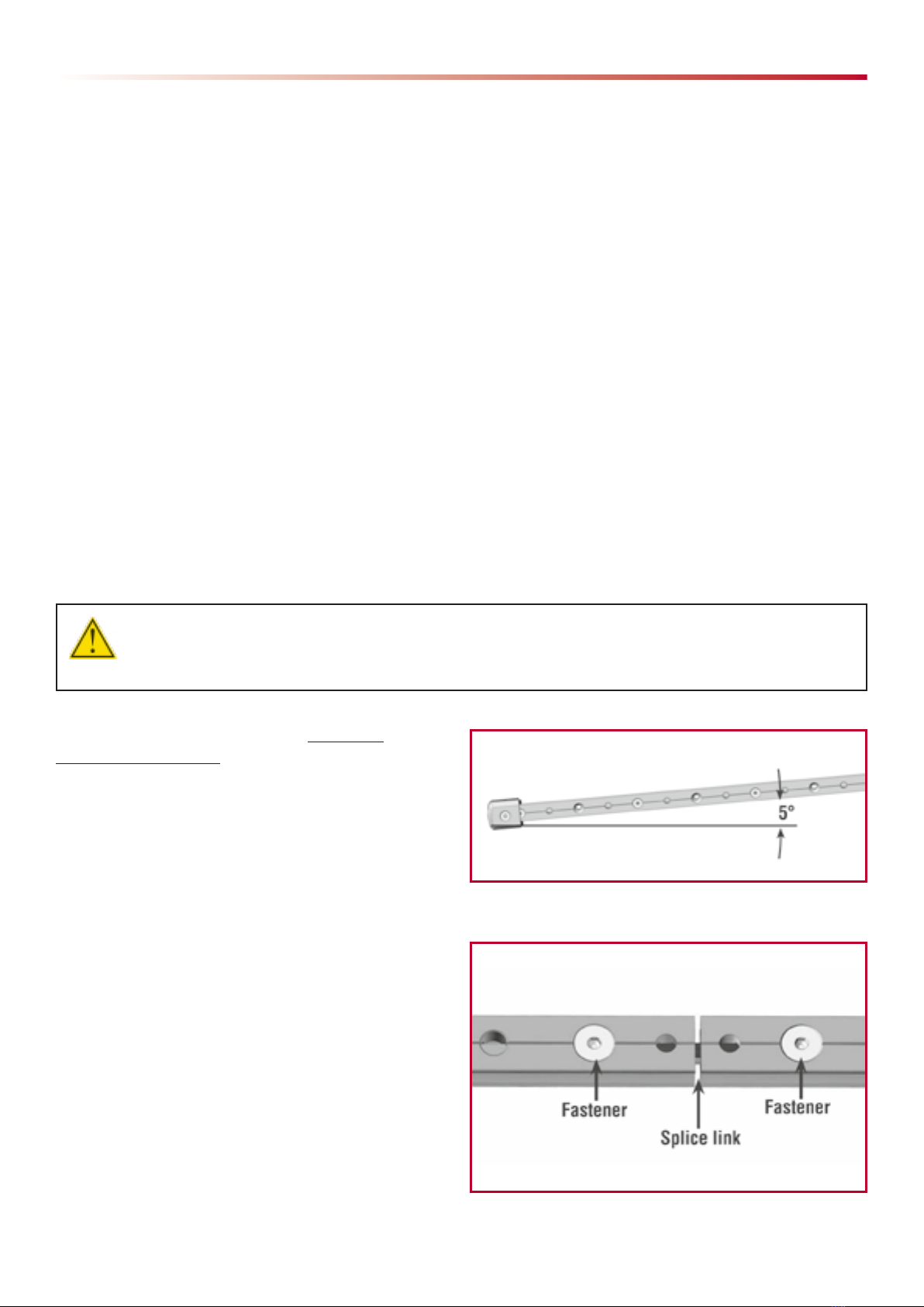
•Load angle limitations: IN9606, IN9606.CLEAR,
IN9565, IN9565.CLEAR, IN9608 and IN9608.CLEAR
Trolleys - Rail must run within 5° of horizontal, but
can be mounted at various angles on the horizontal
mounting structure. Harken IN9606, IN9606.CLEAR,
IN9565, IN9565.CLEAR, IN9608 and IN9608.CLEAR
trolleys have the ability to handle loading at an angle
up to 15° beyond vertical. Loads beyond 15° from
vertical will overload trolley. See image at right.
•Load angle limitations: IN10567, IN10567.CLEAR,
IN10614, IN10614.CLEAR, IN10615 and
IN10615.CLEAR Trolleys - Trolleys with wheeled
toggles are designed to run along a surface,
mounted so that the toggle overhangs the edge.
Ensure that the whole wheel width is in good
contact with the surface to which the rail is
attached. Ensure that the surface is strong enough
to sustain the expected working load and wear.
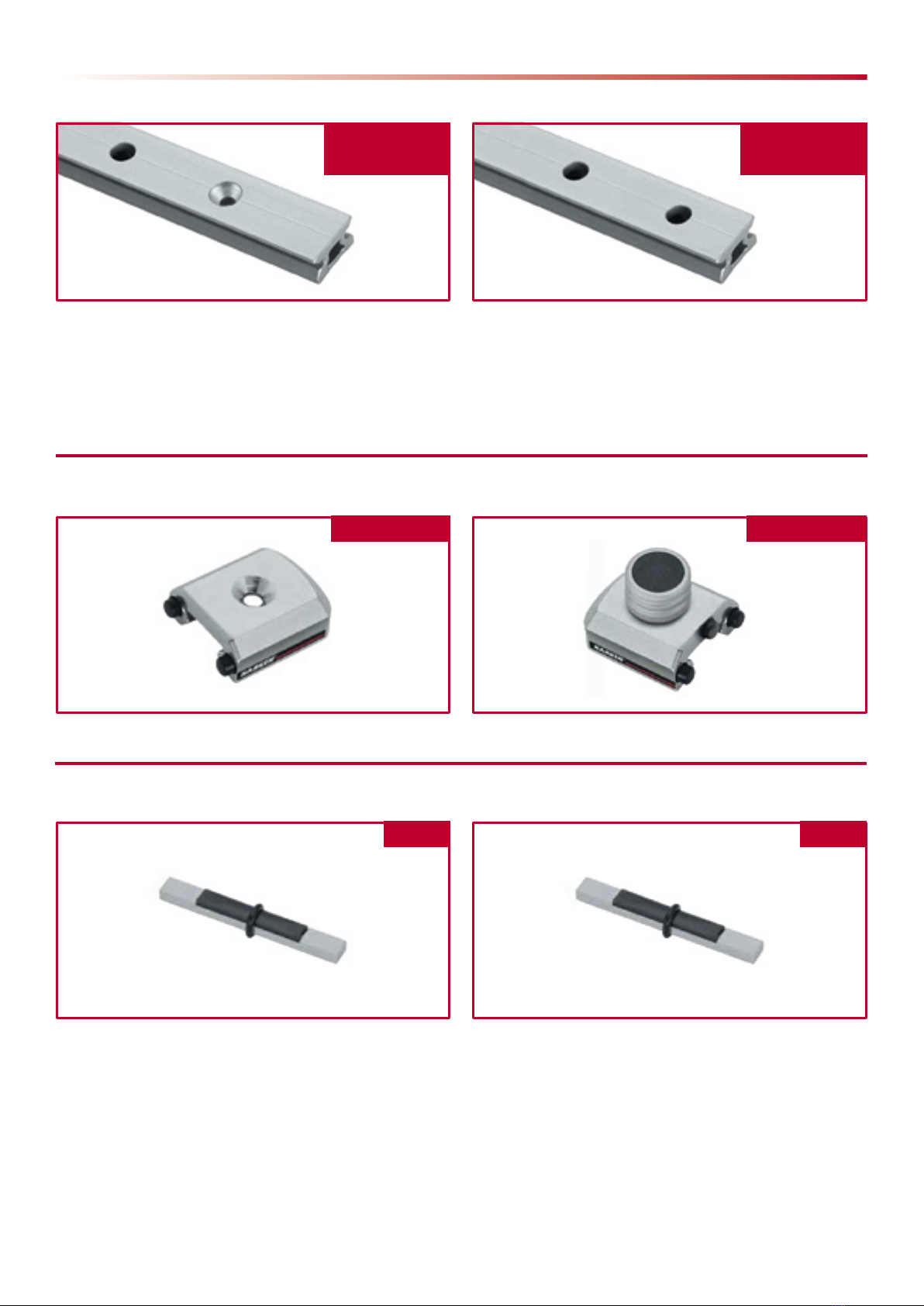
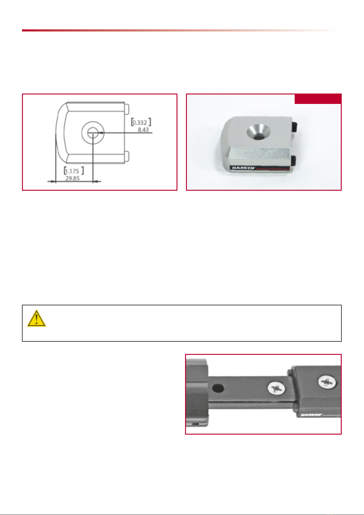
Trolley
15°
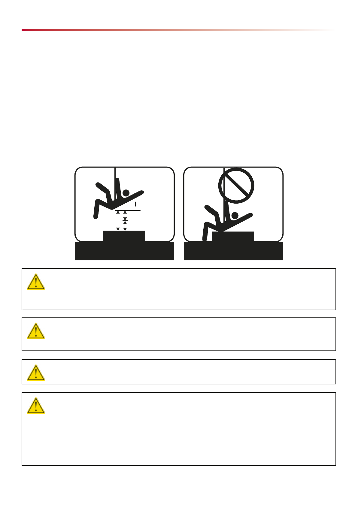
Mounted on angle: Trolleys with
wheeled toggle face outward
Mounted in recess: trolleys with
wheeled toggle for loading over an edge
Trolley with wheeled toggle
DESIGN
DESIGN
Preliminary info
The fall arrest system must be suitably designed by a qualified professional, since the correct installation
and subsequent safety of the users depend on its correct design.
The following are of the utmost importance:
•analysis of the installation location, in order to define the position where the rail will be installed.
•definition of anchor points (where the fasteners will be placed)
•distance between fasteners
•how to fasten the rail to the supporting structure.
Consider all factors that will affect safety during use of this equipment. Rail must be laid out and positioned
strictly in accordance with drawings and specifications supplied by the project authorized architect or other
suitably qualified person. System must meet controlling work at height regulations for country of use.
Installer shall ensure suitability of base materials and structural materials to which rail is fixed, follows
controlling work at height regulations for country of use, and ensures base and structural materials are
capable of sustaining a proof test force.
The weakest structural materials have been simulated in laboratory to evaluate the anchor device and its fastening.
Anyway, the test results don't supply any information on the strucure capability to bear the loads, which can occur
during the use. The capability to bear the loads connected to a fall arrest is subjected to different assessments,
which are excluded from the application of the Regulations for which the product is certified.

12 ENGLISH 20/03/19
NOTE!
The fastening system must always be designed by a qualified professional.
NOTE!
The fall arrest system must be designed,
if applicable, for TOTALLY PREVENTED
or CONTAINED falls, so as to prevent the
significant mechanical stress due to the
risk of falling.
WARNING!
The structure where the R27 rail will be installed must have structural characteristics so as to
support at least the maximum loads of 9 KN in the horizontal and perpendicular dirction, that
could be transmitted in service from the anchor device to the strucutre. This value has been
recorded on the anchor device during the dynamic strenght and integrity test and must be take
into account in order to evaluate the base material, the structural anchorages or the anchor/
fixing correctly. Thus, the system designer must carry out the necessary checks to verify that the
system can be solidly fastened to the structure and that it can withstand the loads in case of fall.
Ceiling, floor, or wall mount
Rail must run within 5° of horizontal, but can be mounted at various angles on the horizontal mounting structure.
Rail can be ceiling mounted, floor mounted, or wall mounted.
Wall mount
Ceiling mount
Floor mount
Placing the rail
WARNING!
In the fall arrest systems it is necessary to verify the absence of sharp edges, which could trailing
or looping lanyards or lifelines.
The design of the fall arrest system must avoid pendulum falls, which could cause post-fall
oscillation of the body with possible impact against obstacles.

20/03/19 ENGLISH 13
Coloured rail
The standard rail is supplied in (CLEAR) anodized aluminium colour. Aluminium rail can be supplied with powder
coating or anodizing coloured, on request. For more information, contact Harken.
Bent rail
The rail can be installed on bent surfaces, which have a minimum bending radius of 15 m. The bending rail
can be done manually in the 3 directions during the installation procedure.
For bending radius included between 2,75 m and 15 m in all the three direction, it's possible to require
the bending rail to Harken. The bent rail has 25 cm of straight rail at the extremity due to the production process.
For more information contact Harken.
Angled wall mount
An angled wall mount must be limited to a maximum
of 15° off vertical. It must be mounted so that the load
on the shackle is taken no more than 15° beyond
vertical. Exception, use trolleys with wheeled toggles
for greater angles.
NOTE!
For optimum trolley performance on the rail, we recommend
to place the rail so that the load is perpendicular
to the sliding plane of the trolley on the rail. Sliding plane
1
2
3

14 ENGLISH 20/03/19
Thermal expansion
Since the rail is made of an aluminium alloy Series 6000 (thermal expansion coefficient: 23x10-6m/°C), during
the design phase, it is necessary to evaluate the rail thermal expansion based on the length of the rail which may
occur when the temperature varies. It is the responsibility of the system designer (qualified engineer) to carefully
evaluate the thermal expansion which will be submitted to the system. The system designer must analyze
the relative coefficient of thermal expansion of rail and mounting material and decide on the appropriate method
of mounting, sealing fasteners, and gaps between rail sections.
As a general rule, leave a space between the end
of one rail segment and the next to allow for thermal
expansion.
Spacing of 3 mm (.118") is appropriate and will allow
the trolley assembly to roll smoothly over the gap. Use
the O-ring supplied with the IN1649 and IN1651 splice
links as a spacer tool to set the gap between the rails.
Be sure to follow mounting instructions for alignment
and fasteners at splice links. Joints must be supported
either side by a fastener 50 mm from rail end.
The R27 rail operating temperature range is -50°C to +80°C. For out-of-range applications, contact Harken
or Harken dealer.
INSTALLATION
The R27 rail must be installed by HARKEN or Harken dealer’s authorized installers or by qualified professionals,
trained to design, install, certify and service the fall arrest system. For a list of HARKEN’s authorized installers,
see the website www.harkenindustrial.com.
The installer carries the full responsibility for a proper and safe installation that is tested to meet all relevant
standards. Normally this would be verified by an independent safety engineer/surveyor
The correct installation must be suitably verified by a supervisor or by a safety officer through calculations or
tests. After completing the installation, the installer must issue the related documents required by reference
regulations and must fix and display near the system access point the sign indicating:
•name and contact info of the manufacturer
•name and contact info of the installing company and name of the installer
•system serial number
•type of fixing devices
•installation date
•maximum number of operators that can connect at the same time
•obligation to use the PPE
•notice to refer to the contents of the anchoring system booklet
•date of the following inspection or the date of the last inspection along with the inspection schedule
•notice to avoid using the anchoring system if the inspection has not been carried out.
INSTALLATION
Joints must be supperted either side
by a fastener 50 mm from rail end.

20/03/19 ENGLISH 15
After the installation, a copy of the installation documents must be submitted to the client. These documents
must be kept in the building for following inspections of the anchoring device.
Rail Installation Guidelines
The fastening of the rail must be made by the installer in the manner defined by the designer (engineer enabled)
who is responsible for the design of the system and the related certification. It is not possible to define a standard
number and type of fasteners, as this is dependent on the material into which the rail is installed, the intended
purpose, and the subsequent maximum load requirement of that purpose.
Rail and fastener specifications
IN1643 and IN1643.CLEAR rail uses M8 (5/16") countersunk fasteners. IN1650 and IN1650.CLEAR rail uses
M6 (¼") socket head fasteners.
Fastener material
All rail listed in this manual is designed to use stainless steel fasteners. Harken does not recommend using
aluminum fasteners for installation. The installer is responsible for the use of non-stainless steel fasteners and
could be held liable. Fasteners must be designed to meet the requirements of controlling work at height regulations
for country of use.
WARNING!
An incorrectly fastened system may not guarantee the adequate resistance to a fall, with conse-
quent grave risks and danger of fatal injuries.
The R27 rail can be installed with a maximum
inclination of 5 degrees with respect to the horizontal
plane.
Joining rail segments
Precise rail alignment at joints is critical for smooth-
running trolleys Fasten each rail segment in the last
fastener hole near the splice link. Use the IN1649 for
IN1643 and IN1643.CLEAR rail with countersunk
fastener or IN1651 for IN1650 and IN1650.CLEAR rail
with socket head fastener and round rods held in the
rail groove. Use spring clamps to align rails during
installation. The splice link is not structural and is used
only to maintain alignment and linearity of the individual
rail segments. See thermal expansion section for using
O-ring as spacer tool.

16 ENGLISH 20/03/19
Drilling holes
Use transfer punch to mark hole centers. Hold rail in
alignment, until secured, with spring or "C" clamps
when marking and drilling holes. The first fastener must
be 50 mm to rail end or less.
Threadlocking fasteners
Always use threadlocking solution or locknuts.
Preventing corrosion between fasteners and rail
Use an anti corrosion paste on the fastener head to prevent galvanic corrosion between fastener and rail. Do not
use for nuts on fastener.
The R27 rail must be connected to the lightning protection system, in compliance with current regulations.
End stop assembly instructions
Using IN1642.CLEAR removable endstops
They allow user to easily remove trolley assemblies for storage away from the elements and for switching trolley
assemblies from one rail to another. The end fitting can be easily removed and inserted, thanks to its spring pin.
NOTE!: Be sure the first rail mounting fastener is located within 50 mm of the rail end.
IN1642.CLEAR
IN1643.CLEAR
IN1643
IN1650.CLEAR
IN1650

20/03/19 ENGLISH 17
Drill a Ø10mm hole in the rail centreline through the
top surface only for the removable endstop.
Endstops must be mounted no farther than 50 mm
from the last fastener fixing rail to structure.
WARNING!
Always be sure the pinstop is securely fastened to a pinstop hole in the rail. The bottom
of the knob must be nearly flush with the body of the endstop. Failure to seat in a pinstop hole
can result in a fall which could result in severe injury or death.
WARNING!
Removable endstops MUST be tethered to the system or a suitable anchor point to prevent falling
objects.
CORRECT INCORRECT

18 ENGLISH 20/03/19
Installing IN9561.CLEAR endstops
Fasten endstops to rail ends using fleathead M8 (5/16") stainless steel fasteners. Drill a M8 threaded hole in the
rail centerline and tap into the rail to mount end stop. Note hole center locations below and plan endstop location
on rail to avoid interference from the predrilled mounting or pinstop holes. Endstops must be mounted no farther
than 50 mm from the last fastener fixing rail to structure. Use an anticorrosion paste on the endstop fastener head
to prevent galvanic corrosion between fastener and rail.
PRELIMINARY AND PERIODICAL CHECKS
Before using the R27 rail, check its condition and visually check each component:
•Check rail for dirt buildup before each use. If the rail has visible dirt or feels gritty, clean the rail ahead of your
travel as part of your maintenance.
•Make sure that: the system components are not deformed, the screws are not loose, there are no signs of wear,
corrosion and build up of dirt. In case of identified faults or damaged parts, do not use the system.
•In particular, check the most critical components: fasteners and (mobile/fixed) end fittings.
WARNING!
If all screws are not fastened securely, rail can separate from mounting surface resulting in a fall,
severe injury, or death.
•Check to make sure screws have not loosened and
are flush with top of rail so trolleys roll smoothly.
Loose screws can also compromise system safety.
Inspect the rail length by running the trolley assembly
the entire length without load. Ensure the trolley
assembly runs freely and hits no screw heads or
obstructions.
IN9561.CLEAR
PRELIMINARY AND PERIODICAL CHECKS

20/03/19 ENGLISH 19
•Check to make sure that endstop screws of the
IN9561 endstop have not loosened. Screws must be
flush with the top of the endstop.
•Check to make sure that pinstop of the IN1642.CLEAR
endstop is securely fastened to a pinstop hole in the
rail. The bottom of the knob must be nearly flush with
the body of the endstop.
WARNING!
If endstop screws loosen or failure
to seat in a pinstop hole, trolleys can roll
off end of rail resulting in a fall, severe
injury or death.
•Visually check that the supporting structure (where the fall arrest system is installed) does not show signs of
deterioration
•In case of faults or damaged parts, contact the safety officer, who will call Harken or Harken dealers’s
authorized personnel or qualified personnel to inspect the system.
•In case of a fall, request an inspection of the fall arrest system to Harken or Harken dealers’s authorized
personnel or to qualified personnel.
WARNING!
Any rail which has been subjected to the forces of arresting a fall or there is any doubt arise
about its condition for safe use, must be immediately withdrawn from use and not used again
until confirmed in writing by an Harken dealers’s authorized personnel or qualified personnel to
inspect the system that it is acceptable to do so.
•In case of lightning, fires or intense weather events, do not use the fall arrest system and call Harken or Harken
dealers’s authorized personnel or qualified personnel to inspect it.
•Check the legibility of the rail markings.
CORRECT
INCORRECT

20 ENGLISH 20/03/19
Annual check
The rail must be thoroughly inspected at least once every 12 months for Fall Arrest specification, or 6 months
for Human Suspension, if regularly used, or before using it after a long period of inactivity. Based on the frequency
of use and on the place of installation of the rail, the maintenance schedule may vary.
WARNING!
The regular periodic examinations are needed procedures for the safety of users because the safety
of users depends upon the continued efficency and durability of the equipment.
Do not use the fall arrest system without performing the compulsory servicing. The inspection performed by
Harken or Harken dealers’s authorized personnel or by qualified personnel, must be recorded in the Maintenance
Record of this Manual.
Moreover the system must be branded with the date of the next inspection or the date of the ispection done.
WARNING!
DO NOT USE the R27 rail if:
• you detect damage, wear, corrosion or deformation on the rail and on the related components
(endstops, anchor/fixing, attaching fasteners...)
• faults are detected during the compulsory periodical inspection
• a fall with consequent stress for the rail has occurred
PACKAGING, STORAGE, TRANSPORTATION
Every rail is supplied by Harken in its original packaging in order to prevent the development of dust and dirt and
potential damages.
Check the packaging integrity and if it is damaged, before istalling the rail proceed with an accurate inspection.
During the storage and the transportation use the original packaging.
Store the rail in a dry, ventilatyed, low umidity and not salt place in order to avoid corrosion and protect the
product against impacts, chemical reagents or possible damages, which may affect the performance of the rail.
MAINTENANCE
In order to keep the rail in proper working conditions, remove any dirt, grease, snow, ice or anything that
can prevent the trolley from sliding correctly from the rail. In particular, clean the rail section in contact with
the trolley’s ball bearings correctly. Only use non-abrasive cleaning tools and mild liquid soaps. Use soapy water
and flush thoroughly with water.
Do not let the rail come into contact with concrete, asphalt, paints, acids, solvents and chemical reagents. For the
trolley maintenance, refer to the proper manual.
CERTIFICATIONS
The R27 rail (IN1643, IN1643.CLEAR, IN1650, IN1650.CLEAR), and components are compliant to the test set out
by Standards EN795:2012 Type D and CEN/TS16415:2013. Furthermore the R27 rail (IN1643, IN1643.CLEAR,
IN1650, IN1650.CLEAR), and components are certified according to the Standard UNI11578:2015.
PACKAGING - STORAGE - TRANSPORTATION
This manual suits for next models
4
Table of contents
Other Harken Industrial Safety Equipment manuals

Harken Industrial
Harken Industrial IN627 User manual

Harken Industrial
Harken Industrial CMC CLUTCH User manual

Harken Industrial
Harken Industrial TR31 User manual

Harken Industrial
Harken Industrial IN647 User manual

Harken Industrial
Harken Industrial ninja User manual

Harken Industrial
Harken Industrial CMC CLUTCH Reference guide

Harken Industrial
Harken Industrial IN106.2FT Guide