Harman JBL MARINE MBP10 User manual

(
MARINE
MBPlO
®
by
HARMAN
r • '
<
MARINE
POWERED SUBWOOFER
OWNER'S
MANUAL
SUBWOOFER ACTIF
MARINE
MODE
D'EMPLOI
SUBWOOFER
ALIMENTADO
PARA
ENTORNOS
MARINOS
MANUAL
DEL
PROPIETARIO www.jbl.com

INSTALLATION
THANK YOU
for
choosing
the
JBL
®
MBP10.
In
order
that
we
may
better
serve
you
should
you
require
warranty
service
for
your
new
subwoofer,
please
retain
your
original
purchase
receipt
and
register
your
new
JBL
marine
subwoofer
online
at
www.jbl.com.
WARNING
Playing
loud
music
in
a
boat
can
hinder
your
ability
to
hear
other
boats,
passengers
and
nearby
swimmers
and
can
permanently
damage
your
hearing.
We
recommend
listening
at
low
or
moderate
levels
while
operating
your
boat.
JBL
accepts
no
liability
for
hearing
loss,
bodily
injury
or
property
damage
resulting
from
the
use
or
misuse
of
this
product.
IMPORTANT
The
MBP1
0
has
been
designed
to
provide
the
kind
of
high-performance
low-frequency
reproduction
that
used
to
require
big,
clumsy
enclosures,
large
amplifiers
and
complex
installation.
To
ensure
maximum
performance,
we
strongly
recommend
that
installation
be
entrusted
to
a
qualified
professional.
Although
these
instructions
explain
how
to
install
the
MBP10
in
a
general
sense,
they
do
not
show
the
specific
installation
methods
for
your
particular
boat.
If
you
feel
you
do
not
have
the
necessary
tools
or
experience,
do
not
attempt
the
installation
yourself;
rather,
ask
your
authorized
JBL
car
audio
or
marine
audio
dealer
about
professional
installation
options.
Remember
to
keep
this
manual
and
your
sales
receipt
in
a
safe
place
for
future
reference.
NOTE:
This
marine
product
is
not
intended
for
automotive
applications.
INSTALLATION WARNINGS AND TIPS
•
Always
wear
protective
eyewear
when
using
tools.
•
Turn
off
the
audio
system
and
other
electrical
devices
before
you
start.
Disconnect
the
(-)
negative
lead
from
your
boat's
battery.
•
At
the
installation
sites,
locate
and
make
a
note
of
all
fuel
lines,
hydraulic
lines,
vacuum
lines
and
electrical
wiring.
Use
extreme
caution
when
cutting
or
drilling
in
and
around
these
areas.
•
Check
clearances
on
both
sides
of
a
planned
mounting
surface
before
drilling
any
holes
or
installing
any
screws.
Remember
that
the
screws
can
extend
behind
the
surface.
Do
not
use
screws
long
enough
to
penetrate
the
boat's
hull.
•
Before
drilling
or
cutting
holes,
use
a
utility
knife
to
remove
unwanted
fabric
or
vjnyl
to
keep
material
from
snagging
in
a
drill
bit.
•
When
routing
cables,
keep
input-signal
cables
away
from
power
cables
and
speaker
wires.
•
When
making
connections,
make
certain
they
are
secure
and
properly
insulated.
•
If
the
amplifier's
fuse
must
be
replaced,
use
only
the
same
type
and
rating
as
that
of
the
original.
Do
not
substitute
another
kind.
CHOOSING A MOUNTING LOCATION
Choose
a
mounting
location
that
doesn't
interfere
with
walkways,
seats
or
the
operation
of
steering,
control
or
safety
mechanisms.
The
MBP10
must
not
interfere
with
the
safe
operation
of
the
boat.
The
best
location
is
usually
a
vertical
wall
that
separates
an
under-seat
storage
compartment
from
the
boat's
interior
space,
as
shown
in
Figure
1.
MOUNTING THE MBP10
CAUTION:
Make
sure
mounting
screws
will
not
puncture
wiring
harnesses,
control
cables,
hydraulic
or
fuel
lines,
the
fuel
tank
or
the
hull.
Some
or
all
of
these
may
be
located
behind
or
under
the
mounting
surface.
Cutting
the
Hole
and
Mounting
the
MBP1O
1.
Check
that
there
is
enough
clearance
behind
the
mounting
surface
to
accommodate
the
MBP10.
2.
Using
the
included
mounting
template,
check
for
clearance
of
the
mounting
flange
and
overall
shape
of
the
MBP10
in
front
of
the
mounting
surface.
3.
Mark
the
hole
in
the
baffle
for
the
MBP1
0
and
the
holes
for
the
mounting
bolts.
4.
Using
a
jigsaw
or
a
rotary
tool
with
a
blade
appropriate
for
the
material
you'll
cut,
cut
along
the
line
that
marks
the
mounting
hole.
5.
Using
a
drill
and
bit,
drill
the
holes
for
the
mounting
screws.
6.
Insert
the
MBP10
in
the
mounting
hole,
align
the
screw
holes,
insert
the
screws
and
then
tighten
them
to
hold
the
MBP10
in
place.
------
---------------------
.,,,------------------
Figure
2
CONNECTIONS
About
Power
and
Ground
Connections:
The
red
B+
wire
and
the
black
ground
wire
should
be
connected
directly
to
the
battery
terminals
in
your
boat.
If
your
boat
has
a
two-battery
system,
connect
the
red
and
black
wires
to
the
battery
that
provides
power
for
your
boat's
accessories
rather
than
the
battery
that
provides
power
to
start
your
boat's
motor.
JBL's
MBP10
is
designed
to
shut
off
if it
senses
that
your
battery's
voltage
has
fallen
below
10
volts,
in
order
to
prevent
your
battery
from
becoming
fully
discharged
while
you're
on
the
water.
Power
Connection
Connect
power,
ground
and
remote
turn-on
signal
to
the
MBP10,
as
shown
in
Figure
3.
Also
observe
these
installation
tips:
•
Use
at
least
#12
AWG
wire
for
the
+BATT(+
12
Vdc)
and
GND
(ground)
connections.
Use
at
least
a
#20
AWG
wire
for
the
REM
(remote)
connection.
•
When
routing
power,
ground,
remote
and
signal
cables,
ensure
that
wires
are
not
able
to
become
entangled
with
cargo,
control
cables,
the
boat's
motor,
passengers'
feet
or
any
other
object
that
could
become
a
safety
hazard.
•
Install
a
fuse
holder
with
a
30A
fuse
within
18"
of
the
battery+
terminal
(see
Figure
5).
•
The
REM
connection
requires
+5
to
+
12
Vdc
signal
for
the
MBP1
0
to
turn
on.
Most
head
units
provide
this
remote
voltage
signal.
Connecting
the
Signal
The
MBP10
includes
a
2-channel
speaker-level
input
and
a
2-channel
line-level
input.
Either
input
connection
type
may
be
used.
Follow
the
diagram
below
to
connect
signal
to
your
MBP10.
Speaker-level
inputs:
Gray:
right
+
Gray/black:
right
-
White:
left+
White/black:
left
-
Red
to
battery
+
Black
to
battery
-
Figure
3

CONTROLS AND FUNCTIONS
The
MBP1
O
has
several
controls
and
indicators
that
simplify
sonic
integration
with
the
rest
of
the
speakers
on
your
boat.
To
gain
access
to
the
controls,
you
must
remove
the
water-tight
rubber
plug
underneath.
To
install
the
cover,
follow
the
arrows
in
Figure
6
and
insert
the
two
screws.
Figure
4.
Rubber
plug
POWER
0
NOTE:
Be
sure
to
replace
the
rubber
plug
after
making
adjustments.
Figure
5.
Installing
cover
Figure
6.
MBP1
0
controls
on
the
front
panel
PHASE
0
180
D
0 0 0
MIN
MAX
50Hz 120Hz
MIN
MAX
GAIN
X-OVER
BASS
BOOST
POWER
0
Power
LED:
This
indicator
will
glow
blue
when
the
MBP10
is
operational.
Gain
Control:
Use
this
control
to
adjust
the
volume
(loudness)
of
the
MBP10,
compared
to
the
loudness
of
the
other
speakers
in
your
boat.
Crossover:
Use
this
control
to
adjust
the
amount
of
high-frequency
information
in
the
MBP1
O's
output.
A
lower
value
means
less
high-frequency
signal
will
be
present
in
the
MBP1
O's
output.
Bass
Boost:
Use
this
control
to
correct
any
perceived
peak
or
dip
in
the
bass
response.
This
control
provides
boost
or
cut
at
50Hz.
Set
the
control
to
any
value
between
OdB
and
+?dB,
according
to
your
preference.
Phase
Control:
Use
this
switch
to
reverse
the
phase
of
the
MBP1
O's
output,
with
respect
to
its
input.
Choose
the
position
(0°
or
180°)
that
sounds
best.
See
"Tuning
the
MBP10."
TUNING THE MBP10
1.
Make
sure
the
head
unit
is
off
and
its
volume
control
is
set
to
minimum.
2.
On
the
MBP1
O's
front
panel,
set
the
Gain
control
to
the
midpoint
position.
3.
Set
the
Crossover
control
to
its
maximum
position
(clockwise).
4.
Set
the
Bass
Boost
control
to
the
minimum
position
(counterclockwise).
5.
Set
Phase
to
0.
0
6.
Turn
on
the
head
unit
and
play
a
favorite
music
track
that
has
substantial
bass.
Set
the
head
unit's
volume
control
to
75%
of
the
total
output
(approximately
3
o'clock
on
rotary
controls).
7.
Listen
to
your
system,
making
a
mental
note
of
the
amount
of
upper
bass
being
reproduced.
8.
Switch
the
Phase
control
to
180°
and
listen
again
for
upper
bass
content.
There
may
be
more
upper
bass,
less
upper
bass,
or
no
change
at
all.
The
position
that
provides
the
most
upper
bass
is
correct.
9.
Adjust
the
Crossover
control
clockwise
or
counterclockwise
until
you
hear
only
low-frequency
information
in
the
output
of
the
MBP10.
For
example,
you
should
NOT
hear
any
vocals
coming
from
the
MBP10
when
seated
in
the
normal
listening
position.
1
a.Adjust
the
Bass
Boost
control
clockwise
to
suit
your
preference.
NOTE:
In
most
cases,
the
steps
above
will
provide
satisfactory
tuning.
However,
the
actual
process
may
require
several
readjustments
of
each
control,
since
the
settings
will
interact
with
each
other.
If
necessary,
consult
your
authorized
JBL
car
or
marine
audio
dealer
for
help
in
tuning
your
system.
NOTE:
Depending
on
the
MBP1
O's
orientation
and
location
in
your
boat,
reversing
the
phase
may
(or
may
not)
increase
or
decrease
the
amount
of
upper
bass
being
reproduced.

TROUBLESHOOTING SPECIFICATIONS
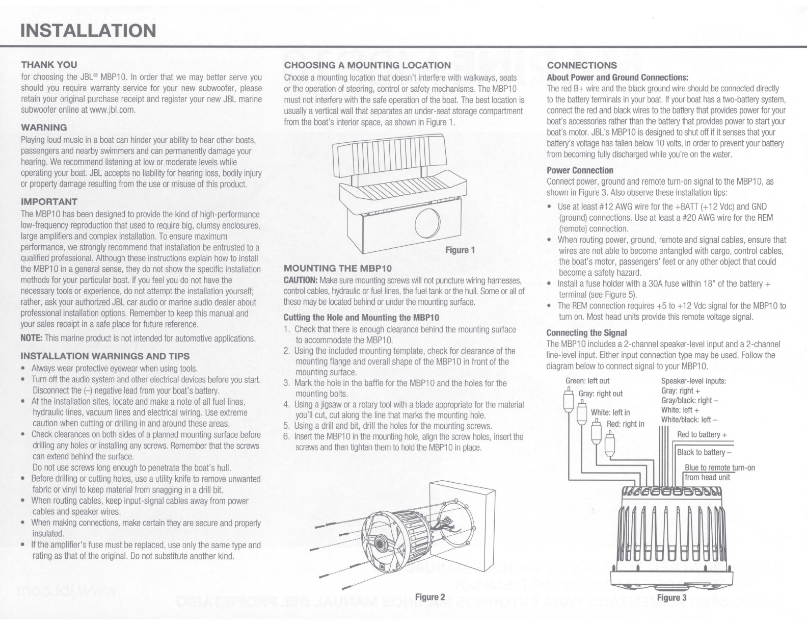
SYMPTOM
LIKELY CAUSE SOLUTION MBP10
• 1
O"
(250mm)
Marine
Powered
Subwoofer
Power
LED
is
not
lit.
Fuse
is
blown.
Fuse
should
be
replaced.
•
Amplifier
Power:
250W
RMS
Head
unit
is
not
functioning
properly.
Check
remote
voltage,
and
power,
ground
or
remote
connections.
The
MBP10
is
designed
to
shut
off
if
the
battery
voltage
falls
below
1
OV.
This
is
to
ensure
that
your
battery
isn't
completely
drained.
Charge
the
boat's
battery.
•
Frequency
Response:
40Hz
-
120Hz
Power
LED
is
lit
but
there
is
no
bass.
MBP1
O
sounds
muddy
or
distorted.
Inputs
are
not
connected.
Head-unit
fader
control
is
not
set
properly
.
Gain
control
is
set
too
high.
Bass
Boost
is
set
too
high.
Check
connections.
Adjust
head-unit
fader
control
to
feed
audio
signals
to
the
MBP10.
Readjust
Gain
control
(see
"Tuning
the
MBP1
O"
on
the
previous
page).
Readjust
Bass
Boost
control
(see
"Tuning
the
MBP1
O"
on
the
previous
page).
•
Signal-to-Noise
Ratio:
81.
1
dB
•
Fuse:
30A
•
Max.
Current
Draw:
14A
•
Idle
Current
Draw:
<1.03A
•
Input
Sensitivity:
Line-Level
Input:
1
OOmV
to
6V
Speaker-Level
Input:
1V
to
13V
•
Crossover
Frequency:
50Hz
to
120Hz
•
Crossover
Slope:
12dB
per
octave
•
Bass
Boost:
OdB
to
+7dB@
50Hz
•
Mounting
Depth:
7-15/16"
(201
mm)
•
Cutout
Diameter:
10-1
/4"
(259mm)
Head-unit
output
is
distorted
or
blown.
•
Overall
Diameter:
11-1/4"
(285mm)
A
valid
serial
number
is
required
for
warranty
coverage.
Features,
specifications
and
appearance
are
subject
to
change
without
notice.
~
HARMAN
~
HARMAN
International
Industries,
Inc.
8500
Balboa
Boulevard,
Northridge,
CA
91329
USA
www.jbl.com
11-1/4
"
285mm
1
1-3/4"
45mm
½---====-~-~=....-.......-'--1
10-1/4"
259mm
©
2018
HARMAN
International
Industries,
Incorporated.
All
rights
reserved.
JBI
is
a
trademark
of
HARMAN
International
Industries,
Incorporated,
registered
in
the
United
States
and/or
other
countries.
Features,
specifications
and
appearance
.are
subject
to
change
without
notice.
7-15/16
"
201mm
Other manuals for JBL MARINE MBP10
1
Other Harman Marine Equipment manuals