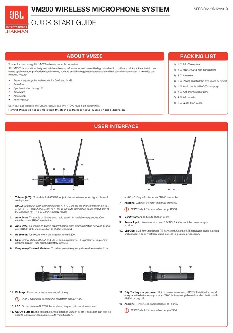
Harman AKG KM200 User manual

KM200
WIRELESS MICROPHONE SYSTEM
无线麦克风系统

CONTENTS
Important Safety Information............................................................ 4
General............................................................................................... 5
Features ............................................................................................. 6
Unpack the system............................................................................ 6
Product Descriptions......................................................................... 7
SR200 Wireless Receiver Front Panel..................................................... 7
SR200 Wireless Receiver Rear Panel...................................................... 7
SR200 Wireless Receiver LCD Display.................................................... 8
HT200 Wireless Transmitter................................................................... 8
HT200 Wireless Transmitter LCD Display ................................................ 9
System Operation .............................................................................. 9
SR200 Installation................................................................................. 9
HT200 Installation............................................................................... 10
Setup The System............................................................................ 11
Specification.................................................................................... 13
Trouble Shooting.............................................................................. 13
Channel Number vs Frequency ....................................................... 14

Disclosure table for poisonous and harmful substances or elements of the name and
content in Product:
PARTS
HAZARDOUS SUBSTANCE
Pb Hg Cd Cr6+ PBB PBDE
METAL PARTS X
O O O O O
CABLES X
O O O O O
“
O
”: Indicates that the concentration of the hazardous substance in homogene-
ous materials in the parts is below the relevant threshold of the SJ/T11363-2006
standard.
“X”: Indicates that the concentration of the hazardous substance of at least one of
all homogeneous materials in the parts is above the relevant threshold of the SJ/
T11363-2006 standard.
China-RoHS Declaration
Symbols Used
The lightning flash with arrowpoint in an equilateral triangle means that there are
dangerous voltages present within the equipment.
WARNING
The exclamation point in an equilateral triangle on the equipment indicates that it is
necessary for the user to refer to the User Manual.
In the User Manual, this symbol marks instructions that the user must follow to ensure
safe operation of the equipment.
!
CAUTION
The “ ” symbol marks important notes, hints, or explanations that make it easier
to use the equipment.
NOTE
When the product reaches the end of its life, separate the housing, electronics
and cables and dispose of all components in accordance with local waste disposal
regulations.
Mindestgrößen
7mm 5mm
<
<
<
5mm
<
<
<
The packaging can be recycled. Dispose of the packaging in a suitable collection
system.
Mindestgrößen
7mm 5mm
<
<
<
5mm
<
<
<

Important Safety Information
SAFETY
1. Read and keep these instructions.
2. Heed and follow all warnings.
3. Do not use this apparatus near water.
4. Clean only with a dry cloth.
5. Do not block any ventilation openings. Install in accordance with the manufacturer’s
instructions.
6. Do not install near any heat sources such as radiators, heat registers, stoves, or other
apparatus (including amplifiers) that produce heat.
7. Do not defeat the safety purpose of the polarized or grounding type plug. A polarized plug has
two blades with one wider than the other. A grounding-type plug has two blades and a third
grounding prong. The wide blade or the third prong is provided for your safety. If the provided
plug does not fit into your outlet, consult an electrician for replacement of the obsolete outlet.
8. Protect the power cord from being walked on or pinched, particularly at plugs, convenience
receptacles, and the point where they exit from the apparatus.
9. Only use attachments/accessories specified by the manufacturer.
10. Use only with a cart, stand, tripod, bracket, or table specified by the manufacturer, or sold with
the apparatus. When a cart is used, use caution when moving the cart/apparatus combination
to avoid injury from tip-over.
11. Unplug this apparatus during lightning storms or when unused for long periods of time.
12. Refer all servicing to qualified service personnel. Servicing is required when the apparatus
has been damaged in any way, such as power-supply cord or plug is damaged, liquid has
been spilled or objects have fallen into the apparatus, the apparatus has been exposed to rain
or moisture, does not operate normally, or has been dropped.
13. Use the mains plug to disconnect the apparatus from the mains.
14. WARNING: TO REDUCE THE RISK OF FIRE OR ELECTRIC SHOCK, DO NOT EXPOSE THIS
APPARATUS TO RAIN OR MOISTURE.
15. DO NOT EXPOSE THIS EQUIPMENT TO DRIPPING OR SPLASHING AND ENSURE THAT NO
OBJECTS FILLED WITH LIQUIDS, SUCH AS VASES, ARE PLACED ON THE EQUIPMENT.
16. THE MAINS PLUG OF THE POWER SUPPLY CORD SHALL REMAIN READILY OPERABLE.
WARNING
TO PREVENT ELECTRIC SHOCK DO NOT REMOVE TOP OR BOTTOM COVERS. NO USER SERVICEABLE
PARTS INSIDE. REFER SERVICING TO QUALIFIED SERVICE PERSONNEL.
WARNING
TO COMPLETELY DISCONNECT THIS EQUIPMENT FROM THE AC MAINS, DISCONNECT THE POWER
SUPPLY CORD PLUG FROM THE AC RECEPTACLE. THE MAINS PLUG OF THE POWER SUPPLY CORD
SHALL REMAIN READILY OPERABLE.
WARNING
TO REDUCE THE RISK OF ELECTRIC SHOCK, GROUNDING OF THE CENTER PIN OF THE PLUG MUST
BE MAINTAINED.
WARNING
REPLACE FUSE WITH SAME TYPE FUSE AND RATING.
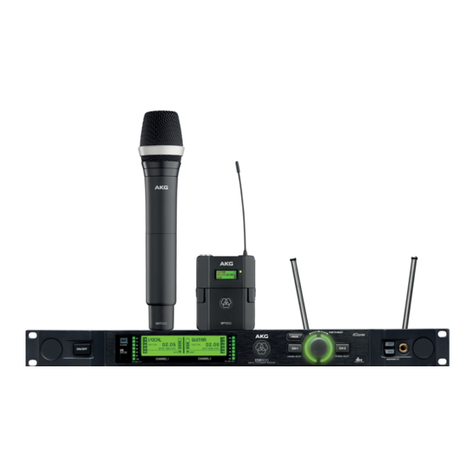
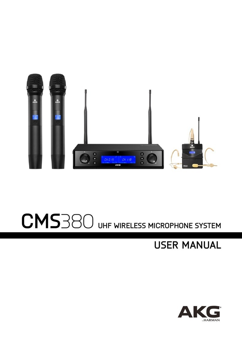
KM200 System
AKG KM200 is a wireless microphone system designed specially for Karaoke application.
Its’ working bandwidth is on UHF with AKG classic wireless circuit to ensure the reliable
transmission stability & sound quality. KM200 has 200 frequency band for option, to
avoid the interference between the different rooms in the Karaoke Club. Leading Hopping
Technology allows auto scan for clean frequency band. Advanced infrared technology,
provides easy & quick setup.
General
• Make sure the grounding cable should be connected to the earth before con-
necting the input and output of this system, avoiding any risk of electric shock.
• To avoid data loss or corruption, malfunctioning, or damage to the system,
never make any changes to the wiring or operate any control on any system
component, or disconnect the system from power while a software update is in
progress.
• To avoid damage to any system component, do not lay, connect, or disconnect
any cables while power to the system is on. Always disconnect the entire system
from power before making any changes to the wiring.
• Custom wiring should only be performed by qualified personnel.
!
CAUTION

6
KM200 System
Features
• UHF frequency band, avoiding interference and reliable transmission stability;
• 200 frequency band option, multi-system use capable;
• Advanced hopping technology;
• Infrared technology for easy & quick setup;
• Anti-collision protection;
• 2 level transmission power option to different application;
• Receiver front panel lock-up function, to avoid mistaken operation;
Unpack the system
AKG KM200 is consisted by 1 x SR200 wireless receiver and 2 x HT200 handhold wireless transmitters. The system is working
on UHF frequency range and provides 200 frequency band option. Within the box, diverse installation accessories were provid-
ed, to satisfy the different application. 2 x SR200 together are able to mount on a standard rack.
• SR200 x 1
Receiver
• HT200 x 2
Transmitter
• Antenna x 2
Connecting to the
SR200 Receiver
• Anti-Rolling Ring
x 2
• Audio Cable x 1
Connecting SR200
to Amplifier
• Power Supply x 1
For SR200 Receiver
• Rack-mount
Bracket x 1
• Connection
Bracket x 1
Connecting 2pcs
SR200 for rack
mount

7
KM200 System
3. Antenna 4. Balance Out2
7. Sensitivity Knob1 8. Sensitivity Knob2
6. Balance Out15. Unbalance Out1. Power Switch 2. Power Connector
Product Descriptions
SR200 Wireless Receiver Front Panel
SR200 Wireless Receiver Rear Panel
1. Output Gain Control 2. Down NavigationKey 3. Function Key 4. IR Sensor 5. LCD Screen 6. Up Navigation Key
1. Output Gain Control: for output gain adjustment.
2. Down Navigation Key: selection Navigation.
3. Function Key: press to confirm the selection.
4. IR Sensor: for Infrared communication with transceiver.
5. LCD Screen: display the current information.
6. Up Navigation Key: selection Navigation.
1. Power Switch: power on/off.
2. Power Connector: connect to power supply.
3. Antenna: UHF antenna.
4. Balance Out2: XLR balance output.
5. Unbalance Out: mix output.
6. Balance Out1: XLR balance output.
7. Sensitivity Knob1: for channel 1 sensitivity adjustment.
8. Sensitivity Knob1: for channel 2 sensitivity adjustment.

8
KM200 System
HT200 Wireless Transmitter
SR200 Wireless Receiver LCD Display
1. RF Signal Indicator 7. Key Lock Icon
3. Channel Indicator4. Frequecy Indicator 5. Output Gain Indicator 6. Mute Icon
2. AF Signal Indicator
1. RF Signal Indicator: show current RF signal status
2. AF Signal Indicator: show current audio signal status
3. Channel Indicator: show current using channel
4. Frequency Indicator: show current working frequency
5. Output Gain Indicator: show current output gain
6. Mute Icon: indicate the system is muted
7. Key Lock Icon: Indicate that all the button on the front
panel are locked except output gain control
1. Wind Shield: protect the microphone capsule inside.
2. Upper Body: together with lower Body to form the hand-
hold and battery compartment.
3. LCD Screen: show the battery & wireless channel
information.
4. On/Off Switch: power on/off the Transmitter.
5. Lower Body: together with upper Body to form the hand-
hold and battery compartment.
6. Antenna: wireless connection with receiver.
2. Upper Body 5. Lower Body 6. Antenna
3. LCD Screen
1. Wind Shield 4. On/O Switch

9
KM200 System
BNC Connector
The V-shape
HT200 Wireless Transmitter LCD Display
SR200 Installation
1. Battery Status Indicator: indicate the battery status.
2. Wireless Channel Status Indicator: indicate the current using wireless channel.
1. Battery Status Indicator
2. Wireless Channel Status Indicator
System Operation
1. Antenna Installation
Screw up the 2 antennas on the BNC connectors of the receiver rear panel. Adjust the angel between the 2 antennas to make
a V-shape as shown on below pictures:

10
KM200 System
2. Rack Installation
AKG has provided the rack installation accessories for KM200, customers are able to combine 2pcs of SR200 with the
provided accessories and install them in the rack as below:
HT200 Installation
Battery Installation
1. Screw down the Lower Body of the handhold, you will see the battery compartment.
2. Insert 2pcs of AA battery based on the +/- indication on the compartment.
3. Select the proper RF power rating by the switch beside the battery compartment, there are “H” & “L” 2 selectable power
rating option.
Front View
Angel View
Transmission
Power Switch
Transmission
Power Switch
Switch Selection:
H - High Power
L - Low Power

11
KM200 System
Setup the Working Frequency
1. Setup Manually
• Press the “Up/Down Navigation Key” on the SR200 to select the RF channel you would like to use;
• Power on the HT200 and aiming the IR sensor on the HT200 to the SR200 IR sensor position;
• Long Press “Up Navigation Key” on the SR200 for 3 seconds, and the LCD screen will display “ “ and start
blinking, it means under channel synchronization process.
• While the synchronization process is done, the channel on HT200 will be adjusted to the same as on SR200, and the
RF indicator will be on.
2. Setup Automatically
• Press the “Function Key” on the SR200, and the LCD screen will display “CH SCA“;
• Press the “Up/Down Navigation Key” to activate the scan process, SR200 will scan the 1st 50 channels for clean
channel, while the clean channel is found, SR200 will stop scanning and display this Clean Channel, if no clean
channel found, SR200 will stop and standby, waiting for the user to press “Up/Down Navigation Key” to activate the
scan process for next 50 channels (ie, every 50 channel scan, SR200 will stop and stand by for activation for next 50
channel scan);
• Power on the HT200 and aiming the IR sensor on the HT200 to the SR200 IR sensor position;
• Long Press “Up Navigation Key” on the SR200 for 3 seconds, and the LCD screen will display “ “ and start
blinking, it means under channel synchronization process.
• While the synchronization process is done, the channel on HT200 will be adjusted to the same as on SR200, and the
RF indicator will be on.
SETUP The System
IR Sensors

12
KM200 System
3. Lock the Key Panel
While the setup process is done, you may lock-up the keys on the SR200 to prevent mistake operation.
To lock-up the key panel:
• Long press the “Function” key over 3 seconds;
• Then the key lock icon will be illuminated on the LCD screen, and now the keys are locked-up.
To unlock the key panel:
• Long press the “Function” key over 3 seconds;
• Then the key lock icon on the LCD screen will disappear, and now the keys are successfully unlocked.
4. Mute the Channel
You may also mute the channel from the SR200 front panel.
To mute the channel:
• Long press the “Down” key of the channel over 3 seconds;
• Then the mute icon will be illuminated on the LCD screen, and now the related channel is muted.
To unmute the channel:
• Long press the “Down” key over 3 seconds;
• Then the mute icon on the LCD screen will disappear, and now the related channel is recovered from mute.
Key Lock Icon Key Lock Icon
Mute Icon Mute Icon

13
KM200 System
Specification
HT200 SR200
Carrier frequencies 740-770 MHz 740-770 MHz
Switching band width up to 30 MHz 30 MHz
Modulation FM FM
Audio transmission bandwidth 50 - 18,000 Hz 50 - 18,000 Hz
Total harmonic distortion at 1 kHz typ. ≤ 0.8% typ. ≤ 0.8%
Signal/S/N ratio typ. 105 dB(A) typ. 105 dB(A)
Transmission power 10 mW, 5 mW -
Voltage supply 2 x 1.5 V battery size AA Power supply unit 12 V / 500 mA
Operating time ≥ 8 hr -
Audio output - XLR symmetric and 6.3 mm jack plug asymmetric:
Adjustable from microphone to line level. Output level
at rated travel: 550 mV eff.
Dimensions Φ35 x 250 mm 210 x 194 x 43 mm
Packaging Dimensions 428 (L) x 332 (W) x 77 (H) mm
Shipping Weight 2500g
Problem Possible cause Remedy
No sound
AC adapter is not connected to receiver and/or power outlet. Connect AC adapter to receiver and/or power outlet.
Receiver is OFF. Push ON/OFF switch to switch receiver ON.
Receiver is not connected to mixer or amplifier. Connect receiver output to mixer or amplifier input.
Output Gain control on receiver is at zero. Turn up Output Gain control.
Transmitter has a different frequency range or is tuned to a different
frequency from the receiver.
Use a transmitter with the same frequency range as the receiver or
tune both to the same frequency.
Transmitter on/off switch is at "OFF" or "MUTE". Set transmitter on/off switch to "ON".
Transmitter batteries are not inserted properly. Insert batteries conforming to "+" and "-" marks.
Transmitter batteries are flat. Replace transmitter batteries.
Transmitter is too far away from receiver. Move closer to receiver.
Obstructions between transmitter and receiver. Remove obstructions.
No line of sight between transmitter and receiver. Avoid spots where you cannot see receiver.
Receiver is too close to metal objects. Remove interfering objects or move receiver away from them.
Noise, crackling,
unwanted signals
Antenna position. Move receiver to a different location.
Interference from other wireless systems, TV, radio, walkie-talkies, or
defective electrical appliances or installations.
Switch off interference sources or defective appliances or use a
KM200 tuned to a different frequency; have electrical installation
checked.
Distortion
GAIN control is set too high or too low. Turn GAIN control up or down until distortion goes away.
Interference from other wireless systems, TV, radio, walkie-talkies, or
defective electrical appliances or installations.
Switch off interference sources or defective appliances or use a
KM200 tuned to a different frequency; have electrical installation
checked.
Antenna position. Move receiver to a different location. If dead spots persist, mark and
avoid them.
Trouble Shooting

14
KM200 System
CH FREQ CH FREQ CH FREQ CH FREQ
1 740.000 26 751.250 51 747.350 76 743.900
2 740.450 27 751.700 52 747.800 77 744.350
3 740.900 28 752.150 53 748.250 78 744.800
4 741.350 29 752.600 54 748.700 79 745.250
5 741.800 30 753.050 55 749.150 80 745.700
6 742.250 31 753.500 56 749.600 81 746.150
7 742.700 32 753.950 57 750.050 82 746.600
8 743.150 33 754.400 58 750.500 83 747.050
9 743.600 34 754.850 59 750.950 84 747.500
10 744.050 35 740.150 60 751.400 85 747.950
11 744.500 36 740.600 61 751.850 86 748.400
12 744.950 37 741.050 62 752.300 87 748.850
13 745.400 38 741.500 63 752.750 88 749.300
14 745.850 39 741.950 64 753.200 89 749.750
15 746.300 40 742.400 65 753.650 90 750.200
16 746.750 41 742.850 66 754.100 91 750.650
17 747.200 42 743.300 67 754.550 92 751.100
18 747.650 43 743.750 68 740.300 93 751.550
19 748.100 44 744.200 69 740.750 94 752.000
20 748.550 45 744.650 70 741.200 95 752.450
21 749.000 46 745.100 74 741.650 96 752.900
22 749.450 47 745.550 75 742.100 97 753.350
23 749.900 48 746.000 76 742.550 98 753.800
24 750.350 49 746.450 74 743.000 99 754.250
25 750.800 50 746.900 75 743.450 100 754.700
CH FREQ CH FREQ CH FREQ CH FREQ
101 755.150 126 766.400 151 762.500 176 759.050
102 755.600 127 766.850 152 762.950 177 759.500
103 756.050 128 767.300 153 763.400 178 759.950
104 756.500 129 767.750 154 763.850 179 760.400
105 756.950 130 768.200 155 764.300 180 760.850
106 757.400 131 768.650 156 764.750 181 761.300
107 757.850 132 769.100 157 765.200 182 761.750
108 758.300 133 769.550 158 765.650 183 762.200
109 758.750 134 740.000 159 766.100 184 762.650
110 759.200 135 755.300 160 766.550 185 763.100
111 759.650 136 755.750 161 767.000 186 763.550
112 760.100 137 756.200 162 767.450 187 764.000
113 760.550 138 756.650 163 767.900 188 764.450
114 761.000 139 757.100 164 768.350 189 764.900
115 761.450 140 757.550 165 768.800 190 765.350
116 761.900 141 758.000 166 769.250 191 765.800
117 762.350 142 758.450 167 769.700 192 766.250
118 762.800 143 758.900 168 755.450 193 766.700
119 763.250 144 759.350 169 755.900 194 767.150
120 763.700 145 759.800 170 756.350 195 767.600
121 764.150 146 760.250 174 756.800 196 768.050
122 764.600 147 760.700 175 757.250 197 768.500
123 765.050 148 761.150 176 757.700 198 768.950
124 765.500 149 761.600 174 758.150 199 769.400
125 765.950 150 762.050 175 758.600 200 769.850
Channel Number vs Frequency

目录
重要安全信息................................................. 17
概述......................................................... 18
产品特点..................................................... 19
打开包装..................................................... 19
产品介绍..................................................... 20
SR200无线接收机前面板........................................ 20
SR200无线接收机后面板........................................ 20
SR200无线接收机LCD屏......................................... 21
HT200无线发射机.............................................. 21
HT200无线发射机LCD屏......................................... 22
系统操作..................................................... 22
SR200安装指引................................................ 22
HT200安装指引................................................ 23
系统设置..................................................... 24
规格参数..................................................... 26
常见问题..................................................... 26
频道与频率对照表............................................. 27

符号说明
说明书和设备上都使用了符号,指出可能对用户或他人造成的伤害以及
财产受损的风险,以便您能够安全、正确地使用设备。指示及其含义如
下。请确保在阅读说明书之前正确理解这些符号的警示。
提醒使用者设备内出现的未绝缘危险电压可能使人遭受电击。
电击提示
此为A级产品,在生活环境中,该产品可能会造成无线电干扰。在这种
情况下,可能需要用户对干扰采取切实可行的措施。
!
警告
表示可能导致操作或设置不成功的内容及一些需要注意的相关信息。
注意
如果您需要丢弃本产品,请勿将其与一般家居废品混放。对于电子产
品的废弃,请遵循当地电子电气设备废弃物指令正确处理、恢复和回
收,将废弃产品统一回收到独立的回收系统。
Mindestgrößen
7mm 5mm
<
<
<
5mm
<
<
<
该产品包装可循环再用。如果您要丢弃该包装,请统一回收到适当的
回收系统。
Mindestgrößen
7mm 5mm
<
<
<
5mm
<
<
<
产品中有毒有害物质或元素的名称及含量:
部件名称
(PARTS)
有毒有害物质或元素 (HAZARDOUS SUBSTANCE)
铅
(Pb)
汞
(Hg)
镉
(Cd)
六价格
(Cr6+)
多溴联苯
(PBB)
多溴二苯醚
(PBDE)
金属部件
(METAL PARTS) X ○ ○ ○ ○ ○
线材
(CABLES) X ○ ○ ○ ○ ○
“○”:表示该有毒有害物质在该部件所有均质材料中的含量均在
SJ/T11363-2006标准规定的限量要求以下。
“X”:表示该有毒有害物质至少在该部件的某一均质材料中的含量
超出SJ/T11363-2006标准规定的限量要求。
中国RoHS声明

重要安全信息
安全操作
1. 阅读本手册。
2. 保留本手册。
3. 留意所有的警告。
4. 遵守本手册中的所有操作说明。
5. 不要在近水区域使用本产品。
6. 仅用干布清洁擦拭本产品。
7. 不要阻挡任何通风口,并严格按照制造商提供的操作说明进行安装。
8. 不要靠近任何热源安装,比如散热器、电热器、火炉或者其他产生热
量的设备(包括功放)。
9. 不要破坏具有安全功效的极性插头或者接地式插头。极性插头有两个
插片,一个宽,一个窄。接地式插头有两个插片和一个接地针,其中
宽插片或者接地针是用来保障您的安全的。如果所提供的插头不适合
您的插座,请咨询联系电工更换适合的插座。
10. 保护电源线。避免电源线被踩踏或者被捻搓。特别注意保护在插头、
便捷插座和电源线接出设备处的电源线。
11. 仅使用制造商指定的附件或选件。
12. 仅使用制造商指定的或者随本产品一同出售的载车、支架、三角架、
托架或者工作台。在使用推车运输设备时,特别注意推车及设备,避
免其翻倒造成伤害。
13. 在有雷电时或者长时间不使用本设备时,请拔掉插头。
14. 所有维修服务必须由有资格的维修人员提供。当设备受到任何形式的
损坏时,比如电源线或者插头被损坏,液体或者异物掉入设备,遭受
雨淋或受潮,不能正常工作,以及被摔碰等情况,都需要维修。
15. 警告:为了减小起火或者电击的风险,不要让设备遭受雨淋或者受
潮。
16. 不要将设备放置在容易遭受滴漏或者喷洒的地方。例如,不要将装有
液体的物品,比如花瓶等放到设备上。
电击提示
为了避免电击,请不要拆卸设备。设备内部无用户可以自行维护的部件。
请向有资格的服务人员咨询。
电击提示
要完全断开此设备与交流电主线的连接,请把电源线插头从交流电插座中
拔出。需要连接电源时,可再次将电源线插头插入交流电插座。
电击提示
为避免电击危险,务必使用插头的接地针脚,切勿移除。
电击提示
更换保险丝时,务必使用同类型同功率的保险丝。

KM200无线麦克风系统
AKG KM200是专门针对KTV房间应用而设计的无线麦克风,其工作在UHF
超高频段,采用了AKG经典的无线发射和接收线路设计,确保传输更稳
定,音质更完美。KM200提供200个可选频道,可满足KTV 娱乐场所内多
套同时使用无干扰。拥有领先的自动扫频技术,一键即可搜索环境中干
净的频点。先进的红外对频技术,使设置更轻松,快速,简单。
概述
• 本产品通过电源线的接地导线接地,为避免电击,必须将接地导
线与大地相连,在对本产品的输入端或输出端进行连接之前,请
务必将本产品正确接地。
• 为避免数据遗失和失误及系统故障和损坏,请勿擅自更改连接线
路,使用任何系统组件对其进行操控,或在进行软件更新时断开
系统电源。
• 为避免对系统组件造成任何损坏,请勿在系统通电状态下,铺
设、连接或断开任何线缆。在对系统连线前,请务必确保已断开
系统的电源连接。
• 此设备的接线工作必须由专业人员或经过培训的人员进行操作。
!
警告

19
KM200系统
产品特点:
• UHF频段,避免干扰,传输更稳定
• 提供200个可选频道,满足多套系统同时使用
• 采用先进的自动扫频技术
• 红外对频技术,实现快速对频
• 防碰撞保护功能
• 手持发射机发射功率两档可调,满足不同应用需求
• 接收机面板锁键功能,避免使用误操作
打开包装
AKG KM200 由一台SR200无线接收机和两只HT200手持无线麦克风组成。系统工作在UHF频率范围,提供
200个可选通道。KM200包装内提供了丰富的安装支架,用户可以根据需要选择使用,两台SR200无线接
收机可以组合安装在标准机柜上。
• SR200 x 1
接收机
• HT200 x 2
发射机
• 天线 x 2
连接SR200接
收机
• 防滚环 x 2
• 音频线 x 1
连接SR200接收
机至功放
• 电源适配器 x 1
为SR200供电
• 机柜安装附件
x 1
• 连接垫片 x 1
连接两台SR200
进行机柜安装

20
KM200系统
1.电源开关
2.电源接口 3.天线 4.平衡输出口2
7.接收灵敏度调节钮1 8.接收灵敏度调节钮2
6.平衡输出口15.非平衡输出口
产品介绍
SR200无线接收机前面板
SR200无线接收机后面板
1.输出增益控制旋钮 2.向下导航键 6.向上导航键
3.功能键 4.红外线通讯头 5. LCD屏
1. 输出增益控制旋钮:用于输出增益调节
2. 向下导航键:用于选择导航菜单
3. 功能键:确认选择
4. 红外线通讯头:与发射机红外线口对接通讯
5. LCD屏:显示目前状态信息
6. 向上导航键:用于选择导航菜单
1. 电源开关:接收机电源开关
2. 电源接口:外接电源适配器
3. 天线:UHF波段天线
4. 平衡输出口2: 第二通道XLR平衡信号输出
5. 非平衡输出口:混合信号输出
6. 平衡输出口1:第一通道XLR平衡信号输出
7. 灵敏度旋钮1: 第一通道灵敏度调节
8. 灵敏度旋钮2: 第二通道灵敏度调节
Table of contents
Other Harman Microphone System manuals

Harman
Harman AKG WMS420 User manual

Harman
Harman AKG CMS380 User manual

Harman
Harman AKG WMS420 User manual

Harman
Harman AKG DMS 700 V2 User manual

Harman
Harman AKG DHT800 User manual

Harman
Harman AKG WMS4500 User manual

Harman
Harman JBL VM300 User manual

Harman
Harman JBL VM200 User manual

Harman
Harman JBL QUANTUM Stream Talk User manual

Harman
Harman AKG DMM12 User manual