LGL KYC User manual

MANUALE DI ISTRUZIONE
INSTRUCTION MANUAL
NOTICE D'INSTRUCTION
BEDIENUNGSANLEITUNG
MANUAL DE INSTRUCCION
EL KİTABI
取扱説明書

TRADUZIONI DELLE ISTRUZIONI ORIGINALI.
TRANSLATION OF THE ORIGINAL INSTRUCTIONS.
TRADUCTIONS DES INSTRUCTIONS D’ORIGINE.
ÜBERSETZUNG DER ORIGINALANLEITUNGEN.
TRADUCCIÓN DE LAS INSTRUCCIONES ORIGINALES.
ORJİNAL TALİMATLARIN TERCÜMESİ.
֯⭘䈤᰾Ⲵ㘫䈁
Scope of supply: Design, manufacture and after sales service of yarn and weft
feeders, measuring winders, stands, creels and oil systems for textile machinery.

L.G.L. Electronics is gratified by your choice
and thanks you for the preference.
Doc. no.: MAN/KYC Rev. 8
ISSUED BY: Service
Manager
APPROVED BY: Technical
Manager
Date: 01/09/2019
Date: 01/09/2019
INSTRUCTION MANUAL

4
INDEX
1 General features 6
1.1 Introduction 6
1.2 KYC information LED 7
1.3 KYC Dip Switches 8
1.4 Steps to do to include the KYC in an infrastructure 9
1.5 WIFI mode: Ad hoc and Soft AP 13
2 Connection 14
2.1.1 Get connection with KYC throguh WIFI or LAN 14
2.1.2 Open KnittingGlobal software based upon JAVA 14
2.1 How to establish a connection between KYC and lap top 14
2.2 Create a shortcut to each knitting machine 15
2.3 Erase undesired feeders from visualization 16
3 Parameters 17
3.1 Feeders parameters 17
3.2 Attivo electronic brake settings: Tdes. dgr and tread dgr 20
3.3 List of parameters 22
4 KLS 23
4.1 KLS: automatic output stop motion system 23
4.2 Button for the learning procedure located on the KYC box 25
4.3 OYB SW Tmr 26
4.4 KLS FAST (Default value = 0) 27
4.5 KLSCm Delay (Default value = 86; min=20; max=100) 27
5 Alarms 28
5.1 Feeders alarms 28
6 Configuration 31
6.1 Machine configuration 31
6.2 Opening of an existing configuration 36

5
INDEX
7 YCM 39
7.1 YCM feature: YARN consumption 39
7.2 YCM table saving 42
7.3 Import the YARN consumption file into open office 43
7.4 Import the YARN consumption file into open office 45
7.5 YCM example 46
7.5.1 Create machine configuration 46
7.5.2 Get yarn consumption information 55
7.6 YARN consumption of belt driven feeders 62
7.6.1 Belt feeder 63
7.6.2 Belt sensor 65
8 Application close 69
8.1 Application close 69

6
1 GENERAL FEATURES
1.1 INTRODUCTION
The KYC is an interface between feeders and lap top.
It is connected to feeders through a communication cable. It has a wireless or a LAN connection
with lap top.
The Lap Top is required to have following features:
1. Internet Explorer, Chrome or Firefox.
2. Wireless or LAN connection.
3. JAVA (Free download from JAVA Web Site).
It takes power supply (24VAC – 35VDC) from LGL power box.

7
1 GENERAL FEATURES
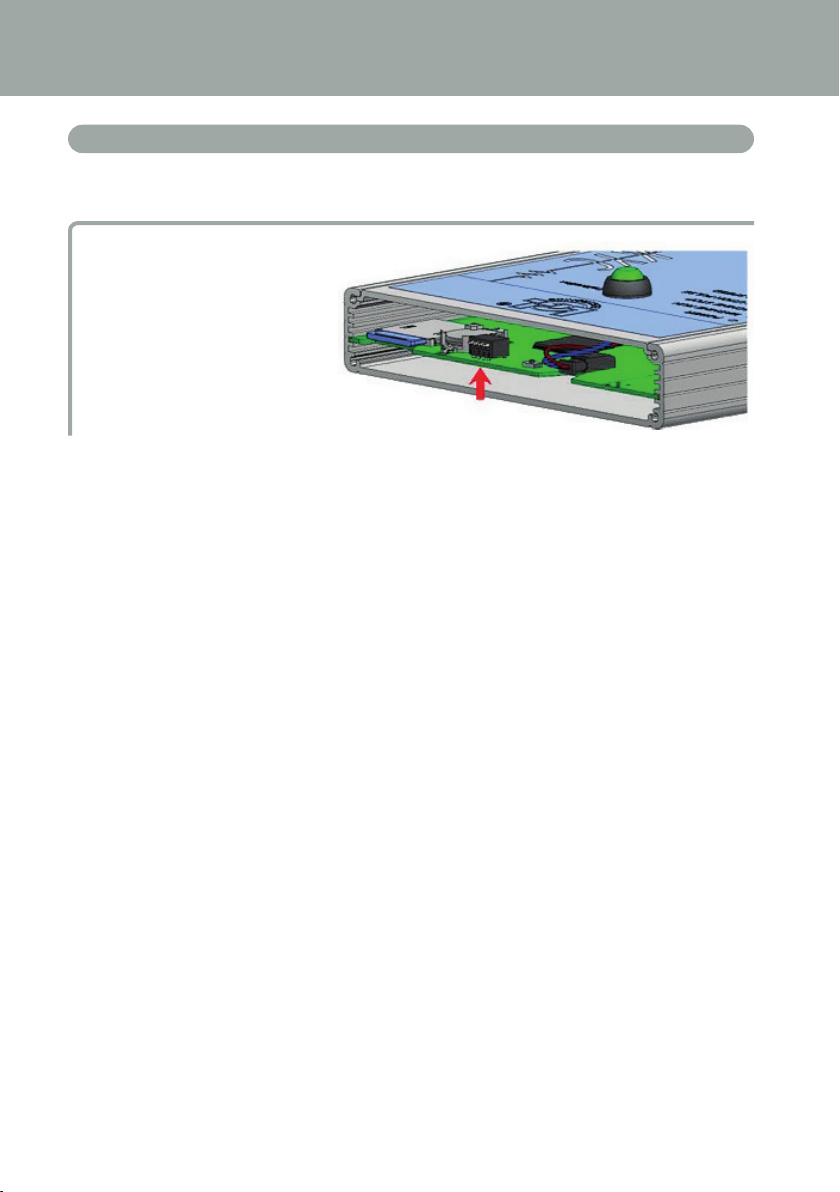
1.2 KYC INFORMATION LED
LED
The KYC device has the following information LED:
1. POWER. It is simply connected to the 5 Volts logic power supply. It indicates that the KYC
is powered up.
2. MACHINE RUN. When this yellow LED is on, the machine runs. If it is off the machine is
standing.
3. MACHINE STOP. When this red LED turns on, it means that the KYC sends a stop signal to
the machine. Normally this led blinks once when the KYC stops the machine. The led does
not stay on because the KYC removes the stop signal, thus permitting the operator to turn
the machine.
4. REVOLUTION PULSE. This yellow LED makes a short lighting when the revolution input
sensor is detected (normally once each machine revolution).
5. INVERTER SPEED. This green LED light is proportional to the INVERTER SPEED (more light
means higher inverter speed).
6. KLS STATUS. This is a bicolor LED: when it is yellow it indicates that KLS function is ena-
bled, if it is red flashing it means that KLS function is disabled.
7. FEEDER STOP. This red LED indicates one or more feeder is in alarm condition.
8. SYNCHRO. This yellow LED flashes when the SYNCH output signal is driven (useful for
LGL technical service).
9. FEEDER BUS. This orange LED flashes when there is communication flowing on the feeders
bus (485 or CAN bus).
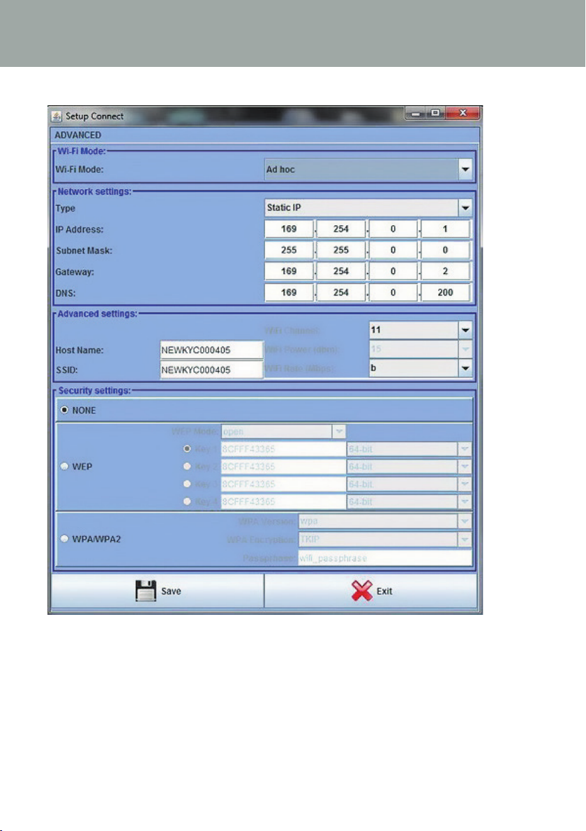
10. Wi-Fi. This is a bicolor LED : when it is yellow lighted it indicates that Wi-Fi connection is
ON. The LED will became orange for a while on each data packet received.
•when the Wi-Fi interface is in ad-hoc or soft ap mode, the LED will become soon yellow
after power-up and it will stay in that state anyway.
•When the Wi-Fi interface is in infrastructure mode, the LED will become yellow only after
that KYC has joined. The Access Point with the configured SSID. If said access point will
shut down, the yellow LED will turn off (with a delay of about 8-10 seconds).
11 . CHECK GROUNDING. This red LED will flash when KYC detects an excessive current
flowing into the RS485 ground wire. This normally means that feeders are not correctly
grounded.

8
1 GENERAL FEATURES
1.3 KYC DIP SWITCHES
KYC V2 has four DIP-SWITCHES
All DIP-SWITCH settings has effect only on the next device reset or power - up.
DS1
Software Upgrade forcing: when it is in OFF state (default configuration) the application
software will start. If it is in ON state, the boot loader will wait indefinitely for the software
upgrade and will prevent application software from running until a valid software is loaded.
DS2
Network interface selection: when it is OFF state the Wi-Fi interface is selected and the
wired Ethernet is disabled. When it is on, Ethernet interface is enabled and Wi-Fi is disabled.
DS3
Feeder bus selection: when it is in OFF state the communication is enabled on the RS485
BUS only and it is disabled on the CAN BUS. On the opposite, when it is in ON state, the CAN
BUS is enabled and RS485 is disabled.
DS4
Default network configuration: when it is in OFF state (default) the network configura-
tion is read from the SD card. When it is in ON state, the network configuration is forced to the
following one :
a. KYC has a static ip address of 169.254.0.1
b. KYC acts as a DHCP server assigning to the DHCP clients a pool from 169.254.0.5 up to
169.254.0.11
c. For the wireless side, the Wi-Fi mode is forced to be ad hoc and without data encryption;
moreover the SSID and the host name are both set to “KYC_DEFAULT”

9
1 GENERAL FEATURES
1.4 STEPS TO DO TO INCLUDE THE KYC IN AN INFRASTRUCTURE
Note: follow this procedure only in case you want to include the KYC in a company network.
After you have connected to the KYC ( in soft ap mode ) with the usual address : 169.254.0.1,
you have to select , from the “File” menu, the submenu “Options” ( like below ).
The program asks for a password :
Enter option1 password
and then press OK button.

10
After a while the “Setup Connect” menu will appear like below :
1 GENERAL FEATURES

11
The fields to be changed are at least the followings :
Wi-fi Mode: you have to change from “Ad Hoc” to “Infrastructure”, or from «soft AP» to «in-
frastructure» (see also pharagraph1.5).
Type: We recommend to select “Static IP” in order to address each KYC with a fixed address
(if you select dynamic addressing you cannot know at priori the IP address).
IP Address: For each KYC you have to set a unique static IP address in order to not create IP
conflicts : i.e. Machine Nr. 1 -> 192.168.0.1; Machine Nr. 2 -> 192.168.0.2, etc.
Subnet Mask: ask to the network administrator (usually 255.255.255.0 or 255.255.0.0).
Gateway: this is necessary just if you would like to reach the KYC from outside the local sub-
net; if you don’t know you should ask to the network administrator or set it to : 0.0.0.0 or the
router / access point IP address.
DNS server: actually not used (this field is provided for future uses), you can set 0.0.0.0 or
the router / access point IP address.
Host Name: this file is the label that appears on the JAVA client upper bar for fast identifica-
tion : this field should describe the machine where the KYC is installed (i.e. : MachineNr01).
SSID: when the infrastructure mode is selected (like in this case), this field is the SSID of the
Access Point that the KYC will use to access the network.
Security Settings: this field select the encryption type and the relative keys.
1 GENERAL FEATURES

12
A configuration example is given below (using WPA-2 Encryption) :
To save the changed configuration, press the Save button: the KYC will reboot itself and will
try to use the new settings.
If you have any problems in the configuration (i.e. : inserted the wrong SSID) there is always
the possibility to revert the KYC to the std. soft ap connection by putting the DS4 dip switch ON
on the KYC device: you can then reconnect in sof ap mode and write the correct configuration
(before pressing Save remember to put DS4 to OFF position otherwise the KYC will reboot in
soft ap mode anyway...).
1 GENERAL FEATURES

13
1.5 WIFI MODE: AD HOC AND SOFT AP
Following the procedure described at point 1.3, there is the possibility to have access to the
“setup connect” menu.
In this menu the voice WI-FI Mode deserves a bit of attention, because the first KYC devices
sold in the market were set “Ad Hoc” by default, while the most recent pieces are set “Soft
AP”. This change is due to the fact that “Ad Hoc” mode is no more supported by Windows
(starting from Windows8 on).
On the contrary “Soft AP” mode works with Windows XP, Windows7, Windows8 and
Windows10.
If you can’t connect WI-FI to the KYC device, one of the reasons could be that you are using
windows 8 or windows10 and the KYC device is set “Ad Hoc”. In this case we suggest to con-
nect through LAN and change this parameter.
1 GENERAL FEATURES

14
2 CONNECTION
2.1 HOW TO ESTABLISH A CONNECTION BETWEEN KYC AND LAP TOP
2.1.1 Get connection with KYC throguh WIFI or LAN
WI-FI
If the netbook is provided by LGL, click on “LGL Connect” icon, located on the desktop. The
machine and the KYC box must be switched on.
If the netbook/Laptop is not provided by LGL, follow the procedure below: Open “net con-
nections” Click on the button “refresh network list” The lap top will search for available nets.
After a little while, one of the found nets will be “LGL KYC00XX”. Press the CONNECT button.
After some seconds the writing “connected” will appear.
LAN
Connect the LAN cable located in the KYC package between KYC and PC.
The communication will be established after a little while.
2.1.2 Open KnittingGlobal software based upon JAVA
A. Double click on KnittingGlobaleExe_10.0XX.jar: the following picture appears:
B. Press Settings – Set IP address. Insert the address of the KYC (169.254.0.1 in the ex-
ample of the picture).
C. Click on OK. The software will automatically close the program and re start it. When the
program restarts, you are connected to the KYC device. Top of the screen the KYC address
and its name (NEWKYC00601 in teh example) appear.

15
2 CONNECTION
Note: The first double click on the KnittingGlobaleExe_10.XX.jar file automatically creates
a LGL FILES folder on the PC under local disc.
We suggest to copy the .jar file into the LGL FILES folder and create a shortcut on the desktop.
It is possible to create a shortcut for each knitting machine, as it is explained in the following
pharagraph.
2.2 CREATE A SHORTCUT TO EACH KNITTING MACHINE
Available from software global knitting 10.18 onwards
1. Copy KnittingGlobaleExe_10.18.jar into LGL_Files folder
2. Create a shortcut on the desktop
3. Open shortcut properties

16
4. In the “Target” tab (“Destinazione” in Italian) add the IP address of the KYC: Here in the
below example we add SPACE 192.168.1.2
5. At the end rename the short cut on the desktop with the machine name.
2.3 ERASE UNDESIRED FEEDERS FROM VISUALIZATION
Select feeders that do not have to be shown,
then press icon:
2 CONNECTION

17
3 PARAMETERS
3.1 FEEDERS PARAMETERS
Press GROUP ALL.
Click on one of the two SELECT PARAMETER buttons.
A parameter list will appear:
Note: The list will be displayed only if there are selected feeders.

18
3 PARAMETERS
Feeder
not selected
Feeder
selected
Click on the parameter which you would like to see and click on “view parameter” (in the
picture Tdes. Dgr).
Note: there is the option to select “single” or “change on all feeders of the same type”.
“single”: the desired parameter will be shown only for one feeder.
“change on all feeders of the same type” means that the desired parameter will be shown for
all connected feeders (if all connected feeders are of the same model).
In the example, the parameter will be shown as in the following picture:
The parameter “Tdes. Dgr” has been displayed and the value is 28 (which means 2,8 grams).
Since there are parameters that may change in time, the system keeps reading the parameter in
real time until the operator does not click on STOP.
It is possible to display two parameters together and, by clicking on RUNNING, the two pa-
rameters are read in real time. In the previous picture “Tdes dgr” and “Tread dgr” are displayed
together and read in real time.

19
3 PARAMETERS
T des. dgr is a read/write parameter, and it is written in white. Read/write means that it is
possible to read the parameter value but also to set a desired value. T read dgr is a read only
parameter, and it is written in grey. Read only means that it is only possible to read the actual
value of the parameter.
In order to set a Tdes.dgr desired value, the new value must be typed into the white tab and
press ENTER.
The new value will be sent to all selected feeders of the same model.
If the operator wants to set a new value only for one specific feeder, he has to deselect all the
other feeders of the same model.
To select all feeders,
click on icon:
To deselect all feeders,
click on icon:

20
3 PARAMETERS
3.2 ATTIVO ELECTRONIC BRAKE SETTINGS: TDES. DGR AND TREAD DGR
It is possible to read actual yarn tension and to program the desired tension on each feeder.
For example in the following picture the KYC is reading Tread dgr and Tdes dgr. These parame-
ters are written in the feeder square because they have been selected form the list (shown in the
previous picture). The system is in continuous reading mode (green bar running at the bottom
and green line surrounding the screen). The value of the parameters are shown in real time.
Table of contents
Other LGL Industrial Equipment manuals
Popular Industrial Equipment manuals by other brands

ISVE
ISVE ES5 DRY KILN Use & maintenance manual

Eaton
Eaton COOPER POWER SERIES Assembly and installation instructions

WAGNER
WAGNER VU 1 Translation of the Original Operating and Assembly Manual

Kongskilde
Kongskilde CPU manual

Atlanta Attachment Company
Atlanta Attachment Company 1390HCB Technical Manual & Parts Lists

HPC
HPC LHR-100 instructions