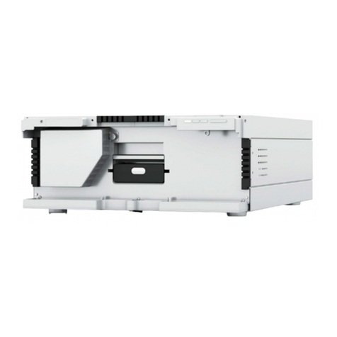
Harvard Bioscience DSI Buxco E-cigarette, Vapor, & Tobacco (EVT) Smoke... User guide

OVERVIEW
This manual provides information on the setup and
operation of the Buxco® E-cig Vape Tobacco (EVT)
Smoke Generator. This document will provide an
overview of the system components, proper
assembly, and basic operation.
PN: 014136-001 Rev 02
E-cigarette, Vapor, & Tobacco (EVT) Smoke Generator User
Application Guide
DSI Buxco®

2| P a g e
014136-001 Rev 02
©2021 Data Sciences International.
Table of Contents
TABLE OF CONTENTS
Welcome......................................................................................................................................... 5
Scientific Background...................................................................................................................... 6
Terminology .......................................................................................................................................................7
System Overview ............................................................................................................................ 9
System Components................................................................................................................................................10
EVT Smoke Generator Controller.....................................................................................................................12
EVT Smoke Generator Station..........................................................................................................................15
QuickStart Guide - Example Experiment ...................................................................................... 20
Step 1 –Connecting the EVT Controller to a Computer and Power Supply ............................................................20
Step 2 - Connecting an EVT Station to the Controller .............................................................................................21
Step 3 –Performing a Leak Test..............................................................................................................................23
Step 4 –Perform a Calibration and Puff Volume Measurement Test .....................................................................25
Performing a Calibration ..................................................................................................................................25
Measuring the Puff Volume .............................................................................................................................32
Step 5 –Configure the Experiment in the Software................................................................................................36
Step 6 - Pre-Experiment Puff Measurement ...........................................................................................................37
Step 7 - Attaching the Cigrarette, E-Cig, Mod, or Pen Device & Chambers.............................................................40
Step 8 - Running the Experiment.............................................................................................................................41
Step 9 - Saving Puff Volume Data............................................................................................................................43
EVT Software User’s Manual......................................................................................................... 46
EVT Smoke Generator - The Main Window.............................................................................................................46
Using Multiple EVT Controllers ........................................................................................................................47
EVT Station Buttons..........................................................................................................................................49
EVT station Graph ............................................................................................................................................50
Puff Properties .................................................................................................................................................50
Leak Test ..........................................................................................................................................................53
Calibrate...........................................................................................................................................................54
Measure Puff....................................................................................................................................................58
Program Settings..............................................................................................................................................59
Hardware Menu ...............................................................................................................................................60
Experiment Information...................................................................................................................................63
Saving and Loading Profiles & Calibrations ......................................................................................................67

3| P a g e
014136-001 Rev 02
©2021 Data Sciences International.
Start Puffing –Running an Experiment ............................................................................................................67
Ending an Experiment and Saving Data ...........................................................................................................68
Information on Data Files........................................................................................................................................69
EVT Experiment Log.CSV ..................................................................................................................................69
Puff Log.CSV .....................................................................................................................................................71
Signals.CSV .......................................................................................................................................................71
Setting up a 1st Generation E-Cig or Traditional Tobacco Cigarettes ........................................... 72
Fitting Options/Attachment Points .........................................................................................................................72
Lighting....................................................................................................................................................................74
Puff Settings ............................................................................................................................................................74
Puff Settings –1st Generation E-Cig .................................................................................................................74
Puff Settings –Traditional Cigarettes...............................................................................................................75
Sidestream Smoke Capture .....................................................................................................................................77
Setting Up a Mod or Pen Device................................................................................................... 79
Attaching a Mod Device or Pen to the EVT Button-Activated Device Holder Kit ....................................................79
Attaching Flow Path Tubing for the Inhalation Port................................................................................................81
Angle/Height Adjustment ................................................................................................................................82
EVT Button-Activated Device Holder Kit ..........................................................................................................83
Setting the Air Pressure for the EVT Button Activation Device Holder Kit.......................................................84
Considerations for Mod Coil Life.............................................................................................................................84
Timing/Mechanical Limitations...............................................................................................................................84
Puff Settings ............................................................................................................................................................85
EVT Smoke Machine Kits:.............................................................................................................. 87
EVT Puff Volume Measurement Kit (Mass flow sensor)..........................................................................................87
In-line Photometer Adapter ....................................................................................................................................88
Physical Setup (Port) ........................................................................................................................................89
Casella Handheld Monitor Setup .....................................................................................................................91
Photometer Software Setup ............................................................................................................................91
Photometer Calibration....................................................................................................................................92
Connecting the EVT In-Line Photometer Kit.....................................................................................................95
Gravimetric Calibration ....................................................................................................................................97
Supplemental Flow Unit –Setting Flow ................................................................................................................101
Push/Pull Tubing Configurations....................................................................................................................101
Adding the Supplemental Flow Unit to An EVT Smoke Machine Station.......................................................102
Using the Mass Dosing Chamber with the EVT Smoke Generator ............................................. 104

4| P a g e
014136-001 Rev 02
©2021 Data Sciences International.
Application Overview ............................................................................................................................................104
Using the Buxco Inhalation Tower with the EVT Smoke Generator........................................... 105
Application Overview ............................................................................................................................................105
Setting Up the EVT Smoke Generator to the Inhalation Tower ............................................................................106
Lifespan, Maintenance, & Troubleshooting, Misc...................................................................... 107
Replacing and Cleaning the Bellows Assembly......................................................................................................107
Cleaning the Bellows ......................................................................................................................................107
Replacing the Bellows ....................................................................................................................................107
Performing an Internal Leak Test ..........................................................................................................................108
Performing a Calibration .......................................................................................................................................111
Custom Cradle –Customer Access to Basic Cradle Geometry (Step File) .............................................................118
Kits, Contents & Uses.................................................................................................................. 119
Replacement EVT Bellows Assemblies ..................................................................................................................119
EVT Smoke Machine Controller Accessory Kit –Parts List ....................................................................................120
EVT Smoke Station Accessory Kit –Parts List........................................................................................................121
EVT Cigarette Holder and Containment Tube –Parts List.....................................................................................122
EVT Button-Activation Device Holder Kit –Parts List............................................................................................123
EVT Puff Volume Measurement Kit –Parts List ....................................................................................................124
EVT In-Line Smoke Reservoir –Parts List ..............................................................................................................125
In-Line Photometer Kit –Parts List........................................................................................................................126
Specifications .............................................................................................................................. 127
Specification ..........................................................................................................................................................127
Dimensions............................................................................................................................................................128
Weight...................................................................................................................................................................128
Operating Environmental Conditions....................................................................................................................128
Technical Support ....................................................................................................................... 130
DSI Technical Support—North America .........................................................................................................130
DSI Technical Support—Europe .....................................................................................................................130
DSI Support Center.........................................................................................................................................130
Schedule a Meeting with Support..................................................................................................................130

5| P a g e
014136-001 Rev 02
©2021 Data Sciences International.
WELCOME
Congratulations on joining the community of users worldwide who rely on DSI’s products to perform preclinical
physiologic research. Thank you for your interest in DSI products. We are committed to providing you with quality
products and services.
This manual will help you get to know your E-Cig Vape Tobacco Smoke Generator (EVT). The structure of the
manual was designed to guide you through setting up your DSI system.
WHAT YOU WILL BE LEARNING
1. Information on the EVT Smoke Generator System Components
2. Quick Start Guide - How to Set Up an Experiment
3. Configuring the EVT Smoke Generator System for Button Activated E-Cig Test Articles
4. Configuring the EVT Smoke Generator System for 1st Generation E-cig Test Articles
5. Configuring the EVT Smoke Generator System for Tobacco Cigarettes
6. How to use the EVT Software
7. Information on Auxiliary Products offered with the EVT Smoke Generator
8. How to set up the EVT Smoke Generator with other Respiratory Products including the Buxco Inhalation
Tower and the Buxco Mass Dosing Chamber

6| P a g e
014136-001 Rev 02
©2021 Data Sciences International.
SCIENTIFIC BACKGROUND
Research is being conducted to determine the risk of E-cigarettes and their potential relationship with chronic or
acute lung disease. These studies are investigating if the use of e-cigarettes and vaping devices significantly
increases the risk of developing lung diseases like asthma, bronchitis, emphysema, and chronic obstructive
pulmonary disease (COPD). To better understand the effect of tobacco, E-cigarettes, E-cig pens, and vaping, the
International Organization of Standards (ISO) has developed standards around cigarettes, E-cigarettes, and vaping
machines; ISO 3308:2012 for tobacco and ISO 20768:2018 for vaping machines. These standards define what is
considered a typical puff from a tobacco or vape device.
These standards describe the conditions where a test device (vaping device, 1st Generation E-Cig, or tobacco
cigarette) can be “smoked” in a consistent manner. These conditions include but are not limited to puff duration,
puff volume, and puff frequency. Below is an example of the “Bell Shaped Puff Profile” used for tobacco cigarettes
and the “Trapezoidal Puff Profile” used for vape devices (Figure 1).
Figure 1 - Tobacco Smoke and Vapor Puff Profile
ISO 3308 also defines the design of a standard cigarette holder and labyrinth seals. Per ISO 20768, this same holder
may also be used for electronic vapor products. Below is an image of the “EVT Labyrinth Seal Assembly” used by
the EVT Generator with tobacco cigarettes or non-actuated electronic vapor products.
Tobacco Smoke
Bell Shaped Puff Profile
Vapor
Trapezoidal Puff Profile

7| P a g e
014136-001 Rev 02
©2021 Data Sciences International.
Figure 2 Labyrinth Seal Holder
The EVT Smoke Generator is designed to generate aerosolized particulates from a cigarette, a 1st Generation E-Cig,
a Pen, or a Mod device by creating “Standard Puffs”, following the standard puff profiles.
TERMINOLOGY
E-cigarettes, sometimes called E-cigs, vapes, or handheld electronic nicotine delivery systems (ENDS), are devices
that create vapor by heating an element that atomizes a liquid solution. This vaper, called Vape, consists of fine
and ultrafine particles of particulate matter, usually nicotine and flavors. There are several different devices
available on the market today that are used for vaping. E-cigarettes come in many shapes and sizes. Most have a
battery, a heating element, and a place to hold a liquid. Some of these devices are activated simply by drawing air
through the device, and some devices are activated by a push-button.
1. Cigarette –This is a traditional tobacco cigarette. DSI uses the Kentucky Research Cigarette 34F, but any
traditional cigarette that is between 7.5mm and 9mm in diameter will fit into the labyrinth seal.
Figure 3 - Cigarette (Traditional)
2. 1st Generation E-Cig –Also known as E-Cigarette or E-Cig or Cig-a-Like. It is a Cigarette shaped device
consisting of a battery and a cartridge containing an atomizer to heat a solution. Some of them are
rechargeable and refillable. Others are intended to be disposed of after use. 1st Generation E-Cig users
inhale the way they would with a regular cigarette. This inhalation activates the atomizer to heat the
liquid in the cartridge and convert the liquid to a vapor. They are designed to mimic the look and feel of
combustible cigarettes.

8| P a g e
014136-001 Rev 02
©2021 Data Sciences International.
Figure 4 - 1st Generation E-cig
3. Pens –Advanced Personal Vaporizers (AVP). Larger than a cigarette, Pens often have a higher capacity
battery, may contain a prefilled cartridge or refillable cartridge. These devices come with a manual switch
for activating the vape solution.
Figure 5 –Pens
4. Mod Device - Mod Vape Devices are much larger than a cigarette with a higher capacity battery and
typically contains a large refillable cartridge. Like a Pen, Mods have a manual activation button.
Figure 6 –Mods

9| P a g e
014136-001 Rev 02
©2021 Data Sciences International.
SYSTEM OVERVIEW
Data Sciences International has developed the Buxco® EVT Smoke Generator. The EVT Smoke Generator is
designed to generate aerosolized particulates from a cigarette, 1st Generation E-Cig, Pen, or Mod devices. The EVT
Smoke Generator is designed to meet both traditional cigarette and e-cig ISO standards for puff profiles, as well as
provide the user the ability to customize puff parameters. The system can be utilized with both button actuated, as
well as non-actuated e-cig devices.
The EVT Smoke Generator is designed for both routine analytical in-vitro testing as well as deliver smoke/vape to
various exposure applications, including Inhalation Tower Exposure, and Mass Dosing Chambers.
Puff inhalation and exhalation are accomplished with the use of a patent-pending bellows design. With this design,
the bellows are set into motion by a precision stepper motor driven piston. Moving the bellows draws smoke or
vapor from the test article into the EVT and finally out to the intended in-vitro or whole animal exposure
apparatus. The smoke or vape is contained in a controlled path from the test article to the exposure apparatus,
preventing contaminants from fouling sensitive components of the EVT generator, or contaminating the aerosol
stream. The bellows assembly components that come in direct contact with smoke or vape product are disposable,
making maintenance simple and inexpensive.
The EVT Smoke Generator can be used with tobacco cigarettes and 1st generation E-cigs. It can also be used with
button activated Pen or Mod devices. To use any button activated device with the EVT Smoke Generator, you will
need a Button Activated Device Holder Accessory Kit (optional).
The EVT Generator can be used as a stand-alone system or in conjunction with several available accessories
including: In-Line Photometer Adapter, Button Activation Kit, In-line Reservoir Kit, and the Buxco Supplemental
Flow Unit. The In-Line Photometer Adapter can be used to measure the concentration of smoke or vape generated
by the EVT. The Supplemental Flow Unit can be used to dilute the output flow to help establish target
concentration levels. The In-line Reservoir can aid in mixing and reduce the pulsatile nature of the concentration
output if desired.
The EVT Smoke Generator supports use of up to three stations. Each station can be used to sample a single test
article. With the use of multiple stations, the EVT Smoke Generator can be configured independently, where one
station can be sampling from a tobacco cigarette and another station from an electronic test article. Also, multiple
test articles can be operated simultaneously, and exhalation outputs combined, providing an increased puff
volume and overall total test material. All three stations can be combined into one smoke or vaping output.

10 | P a g e
014136-001 Rev 02
©2021 Data Sciences International.
SYSTEM COMPONENTS
This section will provide information on the components of the EVT Smoke Generator. Additional accessory items
may be necessary depending on the type of device being sampled or study design.
The following components can be part of an EVT Generator system. Some of these items are optional and are not
necessary, depending on the exposure system configuration.
Figure 7 - EVT Generator Components
1. Buxco EVT Smoke Generator Controller
The Buxco EVT Smoke Generator Controller is the base unit used in the EVT Smoke Generator. The Controller
contains all the electronic and mechanical hardware required to operate an EVT Smoke Station and generate a
standard or customizable “puff”. The EVT Controller also interfaces with the EVT Puff Volume Measurement Kit for
calibration and or post-calibration puff volume assessment. The optional In-Line Photometer Adapter is used to
measure particulate concentration levels of the resultant flow. The Buxco Supplemental Flow Unit can be used to
generate a bias flow for fresh air delivery or to be used to dilute the output concentration stream. The EVT Smoke
Generator Controller communicates with the EVT Software via USB connection. The EVT Smoke Generator
Controller accepts a regulated, external air supply, 100 psi (6.8 bar) max, for use with button actuated devices. For
more information on setting up external air supply, see: Setting the Air Pressure for the EVT Button Activation
Device Holder Kit.

11 | P a g e
014136-001 Rev 02
©2021 Data Sciences International.
2. Buxco EVT Station
The EVT Station is a module that connects to the Controller and houses the hardware mechanisms necessary to
create the “puff”. A high precision stepper motor generates a puff cycle. The motor controls the displacement of a
piston-cylinder, which in turn produces pressure that actuates the bellows assembly. During inhalation, a vacuum
is created at the Inhalation Port. This vacuum draws air through the test article into the bellows assembly. During
exhalation, the piston moves back to its home position, in turn, generating a positive pressure on the bellows,
causing the smoke or vape to be pushed out through the Exhalation Port.
The Buxco EVT Smoke Generator Controller can control up to three Buxco EVT Stations. Each station can be
operated independently from each other, allowing for a sampling of different test articles at the same time.
Multiple stations can, alternatively, be operated synchronously, enabling the outputs to be combined for increased
puff volume and aerosol mass.
3. Buxco Bellows Assembly
Each Buxco EVT Station comes with a patent-pending bellows assembly. The bellows assembly provides two
essential features:
a. The bellows, including check valve lid, contains the smoke or vape and isolates it from the outside
environment and any EVT components that may otherwise be fouled over time.
b. The bellows assembly provides easy maintenance, necessary as cigarette or vape builds up from use.
The bellows assembly is simple to replace for easy maintenance.
4. EVT Puff Volume Measurement Kit
The mass flow meter provided within the EVT Puff Volume Measurement Kit must be used to calibrate the EVT
Station any time a bellows assembly is installed and or when switching from bell-shaped (traditional) to trapezoid
(e-cig) puff profiles. It may also be used to characterize the puff volume any time before or after an experiment.
Puff volume is determined by integrating the flow rate throughout the puff cycle. The pre- and post-puff volume
measurement indicates how much the puff volume may have changed during the experiment. The user can then
decide if they want to make any adjustments in their experiment data based on this change. The pre- and post-puff
volume measurement is stored in the experiment datafile. It is good practice to verify puff volumes using the
measurement kit at the beginning and close of a study.
CAUTION. Test article smoke or vape should never be passed through the mass flow sensor
directly. Failure to keep smoke or vape out of the sensor could invalidate calibrations or
damage the sensor.
5. Buxco Supplemental Flow Unit (optional)
The EVT Controller can power and regulate up to three Buxco Supplemental Flow Units. The flow set point of a
given unit is established within the EVT Software. The in-line Photometer Adapter can be used in conjunction with
the Supplemental Flow Unit to provide additional control over aerosol concentration levels. With the use of a
Supplemental Flow Unit, concentration levels below that which can be established with the use of the EVT alone
can be achieved.

12 | P a g e
014136-001 Rev 02
©2021 Data Sciences International.
6. In-Line Photometer Kit (optional)
The Buxco In-Line Photometer can be used to measure the concentration levels of smoke or vape being delivered
to an in-vitro or in-vivo exposure system. The In-Line Photometer measures aerosol concentration levels being
delivered to the exposure system and provides that information to the Controller and reported out by the EVT
software.
EVT SMOKE GENERATOR CONTROLLER
The EVT Smoke Generator Controller is designed to be the interface between the EVT Smoke Generator Stations,
EVT Puff Volume Measurement Kit, the EVT In-Line Photometer Adapter, and the computer with EVT Software. The
Controller houses the pneumatic, electrical, and mechanical connections for the station, as well as various
accessories. It communicates via USB with the EVT software. The EVT Smoke Generator Controller can control up
to three EVT Stations.
The EVT Controller Left Side Panel allows for connecting three auxiliary items; the Buxco Supplemental Flow Unit
used to control dilution rates or provide supplemental fresh airflow, the In-line Photometer Adapter for measuring
smoke/vape aerosol concentration levels and accumulated mass, and the EVT Puff Volume Measurement Kit used
during calibration or when validating puff volumes.
Figure 8 - EVT Smoke Generator Controller

13 | P a g e
014136-001 Rev 02
©2021 Data Sciences International.
Figure 9 - EVT Smoke Generator Controller
1. On/Off Switch
It is used to turn the power to the EVT Controlled on and off.
2. Button Activation Ports
These three pneumatic ports are for use with optional Button-Activated Device Holder Kit(s). With the use of the
kit(s), Pen and or Mod-type actuated devices can be triggered synchronously with puff generation (See EVT Button-
Activation Kit under Auxiliary Attachments for more details).
3. Photometer Inputs
The EVT Controller left side panel has two 3.5mm phone jacks designed to accept analog signals from the EVT In-
line Photometer. Signals from the photometer are connected to the EVT Front Panel to be read by the EVT
Software.
4. I2C Connectors
The I2C Connectors are used to connect the EVT Puff Volume Measurement Kit or Supplemental Flow Units to the
EVT Smoke Generator Controller. The first I2C connection can be used with either an EVT Puff Volume
Measurement Sensor, or a Supplemental Flow Unit. The 2nd and 3rd I2C connections are to be used only with
Supplemental Flow Unit(s).
5. Pumps Connectors
The EVT Controller can connect to up to three Supplemental Flow Units, providing individual control for each. The
Pump connectors work in conjunction with the Regulation connectors to control the flow rate of the Supplemental
Flow Unit. One I2C, one Pump Connector, and one Regulation Connector is needed for each Supplemental Flow
Unit.

14 | P a g e
014136-001 Rev 02
©2021 Data Sciences International.
6. Regulation Connectors
The EVT Regulation Connectors are used in conjunction with the Pump Connectors to operate Supplemental Flow
Unit(s). One I2C, one Pump Connector, and one Regulation Connector is needed for each Supplemental Flow Unit.
7. External Air Source
The EVT Smoke Generator Controller requires an external air supply when used with the EVT Button-Activated
Device Holder Kit. It is not necessary for non-button activated products.
8. USB Connector
The EVT Smoke Generator Controller communicates with the EVT Software via standard USB connection.
9. Power Supply Connector
The EVT Generator is powered via an external power supply.
CAUTION. Only an approved DSI Power Supply should be used with the EVT Smoke
Generator Controller.

15 | P a g e
014136-001 Rev 02
©2021 Data Sciences International.
EVT SMOKE GENERATOR STATION
The EVT Smoke Station generates the desired puff profiles by pulling smoke/vapor into and out of the bellows
assembly using a precision stepper motor. Each station contains a stepper motor, piston cylinder, and bellows
assembly such that each station can function independently. Puffing with multiple stations can also be
synchronized through the EVT Controller if desired, allowing the exhale ports to be combined. This provides a
larger puff volume than can be delivered by each station independently.
Figure 10 - EVT Station
1. EVT Station Inhale Port
The Inhalation Port is where the Tobacco, 1st Generation E-Cig, or Vape device will be connected. Smoke/vape is
drawn into the bellows assembly from the tobacco/vape source at the Inhalation Port.
2. EVT Station Exhale Port
The Exhalation Port is where the puff sample exits the bellows assembly. From here, it can be plumbed directly to
an exposure assembly or diluted with additional air supplied by a Supplemental Flow Unitor measured for
concentration levels with an In-line Photometer.

16 | P a g e
014136-001 Rev 02
©2021 Data Sciences International.
3. EVT Bellows Assembly
Generating tobacco smoke or vape samples creates a harsh environment for sensitive electronic and mechanical
components. Residue can cause early failure, particularly on moving parts and electronic components. The Buxco
EVT Station is designed to capture and control tobacco and vape samples isolating the aerosol from the external
environment and minimizing exposure to any sensitive EVT components. The bellows assembly is intended to be
easily removed and made disposable, making maintenance effortless and inexpensive.
Figure 11 - Bellows Assembly
4. EVT Station Panel Connector
The EVT Station is connected to the EVT Smoke Generator Controller through a blind-mate connector allowing for
quick, easy connect and disconnect. All power and communication between the Controller and the station are
done through this connector.
STEPS TO CONNECT AND REMOVE AN EVT STATION FROM AN EVT SMOKE GENERATOR
CONTROLLER
It is easy to connect and remove an EVT Station from an EVT Smoke Generator Controller
1. Place the EVT Smoke Generator Controller on a flat, stable surface.
2. With EVT power switch in the off position, attach the provided power supply between Controller and
power outlet. See Figure 9, item 9, for power connector on Controller.
3. Lift the EVT Station by the handle and tilt the bellows side slightly downwards.
4. Insert the bellows side of the station into the alignment tabs located on the top right side of the
Controller.
5. Once the bellows side of the station is seated in the alignment tabs, make sure the alignment pins and
guides are aligned and push the back of the station onto the Controller.

17 | P a g e
014136-001 Rev 02
©2021 Data Sciences International.
Figure 12 - Attaching the Station to the Controller
Turn on the EVT Controller. Verify that power is being applied to the EVT Station by checking that the blue LED is
illuminated, as shown by the picture in Figure 13.Note, LED may take a few seconds before lighting as the motor
driver initiates, and the system verifies the station piston is at the “home” position.
Figure 13
CAUTION. Always make sure the Controller Power is off before attaching or detaching the station.
Failure to do so could damage the Controller or station. This is particularly critical if the station is
under power and actively puffing. The system does contain fail-safe spring contacts to minimize such
risks, but it is still good practice.

18 | P a g e
014136-001 Rev 02
©2021 Data Sciences International.
Also, make sure that the light in the station comes on when the Controller is powered up. If the light
does not come on, press down on the back of the station to make sure it is fully seated into the
Controller connector.
PHYSICAL SETUP (INHALE PORT)
The EVT Station can be configured to capture “Puffs” from different devices, including tobacco cigarettes, 1st
Generation E-Cigs, Pens, and Mods. More information on these different configurations is available in the
appropriate sections to follow.
Figure 14 - 1st Generation E-Cig and Mod Example
BELLOWS ASSEMBLY
DSI has developed a unique approach to simulating a “puff” from tobacco or vape devices. A puff is achieved by
drawing air through the cigarette or vaping device into the bellows assembly through the Inhale Port and back out
through the Exhale Port. The volume and speed of the puff are established by the precise control of the stepper
motor and piston. This control allows the system to produce ISO Standard Puffs with a high degree of accuracy (see
Figure 15) but also enables users to specify custom puff parameters.
As the stepper motor actuates the piston, the pressure generated first expands the bellows, a vacuum is created,
drawing air through the cigarette or vaping device. During exhale, the stepper motor returns the piston to the
home position, in turn generating a positive pressure that collapses the bellows, pushing the sample of smoke or
vape collected in the bellows out through the Exhale Port.

19 | P a g e
014136-001 Rev 02
©2021 Data Sciences International.
Figure 15 –ISO Standard Puffs for Tobacco and Vape
The bellows, and the valves contained within the bellows lid, are the only moving parts exposed to the harsh
environment of smoke or vape aerosol. The aerosol is contained within the bellows assembly, making them the
only parts that require regular cleaning and or change out.
CHANGING AND CLEANING THE BELLOWS ASSEMBLY
The bellows assembly, which contains the bellows and the bellows lid with inhale and exhale valves, are exposed
to contaminants from the tobacco smoke and vape. This may cause the bellows and valves to become sticky over
time. The bellows assembly is designed to be disposable and should be replaced with a new bellows assembly
when excessive contamination is visible that cannot be easily cleaned. Depending on how much it has been used, it
is possible to clean the bellows and the bellows lid valves periodically.
For more information on how to change and clean the bellows assembly, please see ”Replacing and Cleaning the
Bellows Assembly” in the “Lifespan, Maintenance, & Troubleshooting, Misc” section of the manual.

20 | P a g e
014136-001 Rev 02
©2021 Data Sciences International.
QUICKSTART GUIDE - EXAMPLE EXPERIMENT
The following is an example of how the EVT Smoke Generator and the EVT Software would be used in an
experiment. This example will walk you through each step needed to set up and run an experiment and show you
how easy it is to begin using the EVT.
For this example, we will use an 1st Generation E-Cig. The cigarette will be attached to the EVT using the Labyrinth
Seal Assembly. We will not be using the sidestream containment tube, so this test should be done in a fume hood
or area where any sidestream smoke can be removed.
CAUTION. Please consult your institution’s guidelines for proper containment and PPE when
working with smoke and or vape aerosol.
Before proceeding through this section, please install the EVT Software on the PC you plan to use with your EVT
system. The EVT software is located on the USB drive provided.
To install, simply locate the EVTSetup application on the USB drive, double click, and follow the instructions in the
installation wizard.
STEP 1 –CONNECTING THE EVT CONTROLLER TO A COMPUTER AND POWER SUPPLY
The EVT is powered by a power supply brick plugged into the back of the controller. The Controller communicates
with the EVT Software on a PC via a USB cable. Both power supply and USB cable are provided with the EVT
system.
Once the power supply and USB cable have been connected, make sure EVT Controller is powered off before
attaching station.
Table of contents
Other Harvard Bioscience Laboratory Equipment manuals
Harvard Bioscience
Harvard Bioscience BTX Tweezertrodes User manual

Harvard Bioscience
Harvard Bioscience CMA 470 User manual
Harvard Bioscience
Harvard Bioscience BTX AgilePulse PLUS User manual

Harvard Bioscience
Harvard Bioscience Biochrom Libra S6+ User manual

Harvard Bioscience
Harvard Bioscience BTX Oocyte Petri Electrode 45-2059 User manual

Harvard Bioscience
Harvard Bioscience Multi Channel Systems Smart Ephys... User guide
