EN
5
2.1. Insulation and Wall Materials of the
Sauna Room
In an electrically heated sauna, all the massive wall
surfaces which store plenty of heat (such as bricks,
glass blocks, plaster etc.), must be sufficiently
insulated in order to keep the heater output at a
reasonably low level.
A wall and ceiling construction can be considered
to have efficient thermal insulation if:
• the thickness of carefully fitted insulating wool
inside the house is 100 mm (minimum 50 mm).
• the moisture protection consists of e.g.
aluminium paper with tightly taped edges. The
paper must be fitted so that the glossy side is
towards the inside of the sauna.
• there is a 10 mm vent gap between the
moisture protection and panel boards
(recommendation).
• the inside is covered by 12–16 mm thick
panelling.
• there is a vent gap of a few millimetres at the
top of the wall covering at the edge of the
ceiling panelling.
When aiming at a reasonable heater output, it may
be advisable to lower the ceiling of the sauna (normally
2100–2300 mm, minimum height 1900 mm). As a
result, the volume of the sauna is decreased, and a
smaller heater output may be sufficient. The ceiling
can be lowered so that the ceiling joists are fixed
at a suitable height. The spaces between the joists
are insulated (minimum insulation 100 mm) and
surfaced as described above.
Because heat goes upwards, a maximum distance
of 1100–1200 mm is recommended between the
bench and ceiling.
NOTE! Consult fire-extinguishing authorities to
find out which part of the fireproof wall may be
insulated.
NOTE! The protection of the walls or ceiling with
heat protection, such as mineral board fitted directly
on the wall or ceiling, may cause the temperature
of the wall and ceiling materials to rise dangerously
high.
2.1.1. Blackening of the sauna walls
Wooden material in a sauna, such as panels, blackens
with age. The blackening process is sped up by
sunlight and the heat from the heater. If the wall
surfaces have been processed with protective panel
agents, the blackening of the surface of the wall
above the heater can be seen quite quickly depending
on the protective agent used. The blackening is due
to the fact that the protective agents have less
resistance to heat than unprocessed wood do. This
has been proven in practical tests. The micronic
mineral aggregate that crumbles from the stones
on the stove may blacken the wall surface near the
heater.
When following the manufacturer’s approved
guidelines in the installation of the sauna heater,
the heater will not heat up enough to endanger the
flammable material in the sauna room. The maximum
temperature allowed in the wall and ceiling surfaces
of the sauna room is +140 degrees Celsius.
Sauna heaters equipped with CE signs meet all
of the regulations for sauna installations. Proper
authorities monitor that the regulations are being
followed.
2.2. Sauna Room Floor
Due to a large variation in temperature, the sauna
stones disintegrate in use.
Small pieces of stone are washed down on the
sauna room floor along with the water thrown
on the stones. Hot pieces of stone may damage
floor coverings installed underneath and near the
heater.
A light-coloured joint grout, used for a tiled floor,
may absorb impurities from the stones and water
(e.g. iron content).
To prevent aesthetic damage (due to the reasons
presented above) only dark joint grouts and floor
coverings made of rock materials should be used
underneat and near the heater.
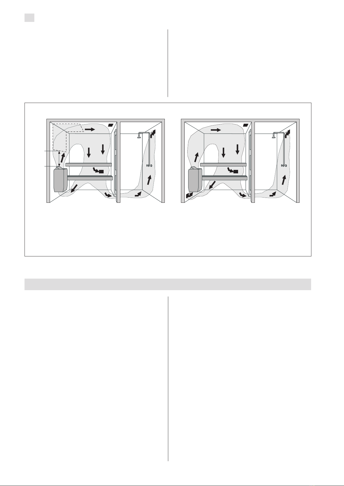
2.3. Heater Output
When the walls and ceiling are covered with panels,
and the insulation behind the panels is sufficient
to prevent thermal flow into the wall materials,
the heater output is defined according to the cubic
volume of the sauna. See table 1.
If the sauna has visible uninsulated wall surfaces,
such as walls covered with brick, glass block, concrete
or tile, each square metre of said wall surface causes
the cubic volume of the sauna to increase by 1.2 m3.
The heater output is then selected according to the
values given in the table.
Because log walls are heated slowly, the cubic
volume of a log sauna should be multiplied by 1.5,
and the heater output should then be selected on
the basis of this information.
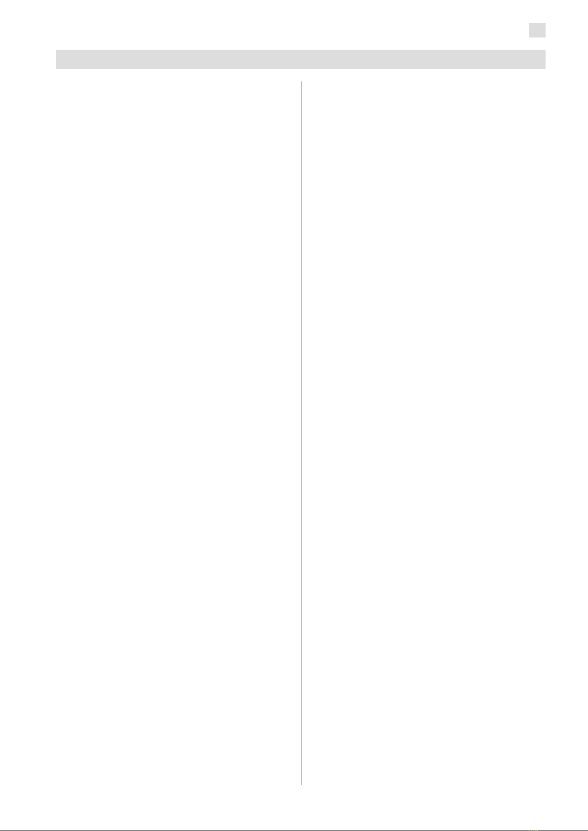
2.4. Ventilation of the Sauna Room
Sufficient ventilation is extremely important for the
sauna. The air in the sauna room should be changed
six times per hour. The air supply pipe should be
located at a minimum height of 500 mm above
the heater. The pipe diameter should be about 50–
100 mm.
The exhaust air of the sauna room should be taken
from as far from the heater as possible, but near the
floor level. The crosscut area of the exhaust air vent
should be twice that of the supply air pipe.
Exhaust air should be led directly into the air
chimney, or, by using an exhaust pipe starting near
the floor level, into a vent in the upper part of the
sauna. Exhaust air can also be led out through an
exhaust air vent in the washing room through a
100–150 mm opening under the sauna door.
For the above-mentioned system, mechanical ven-
tilation is necessary.
If the heater is mounted in a ready-made sauna,
the instructions of the sauna manufacturer should
2. THE SAUNA ROOM