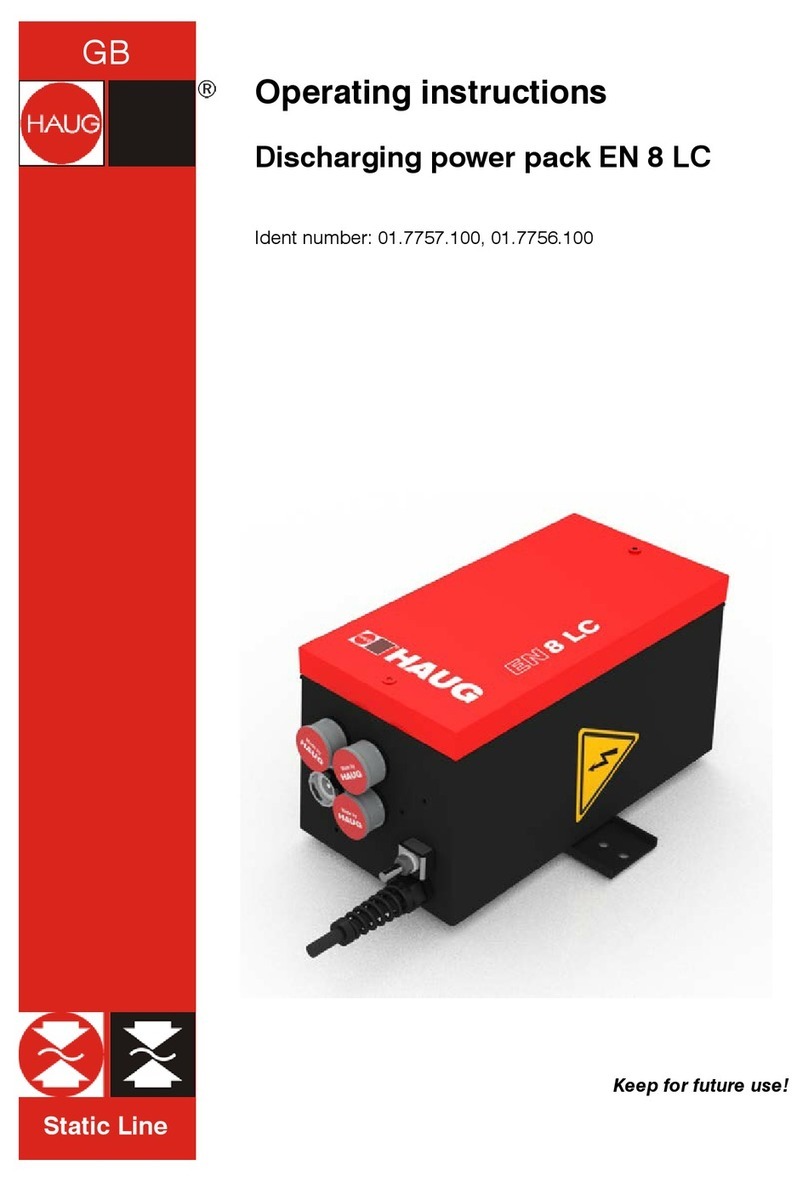
Haug EN 15 Ex User manual

Ex Line
Instruction manual
EN 15 Ex power pack
Ident number: 01.7752.XXX (230 V), 01.7753.XXX (115 V)
Keep for future reference!
EN


Table of contents
1Lieferumfang ................................................................ 4
2Benutzerhinweise ........................................................ 5
2.1 Symbolik in der Bedienungsanleitung ............................... 5
3Sicherheit...................................................................... 7
3.1 Bestimmungsgemäß verwenden....................................... 8
4Geräteübersicht ........................................................... 9
5Installieren .................................................................. 11
6Fehler beheben .......................................................... 16
6.1 Sicherung austauschen................................................... 17
7Technische Daten ...................................................... 18
7.1 Kenndaten und Spezifikationen....................................... 18
7.2 Versorgungsspannung .................................................... 18
7.3 Kennzeichnung................................................................ 18
7.4 Anzugsdrehmomente ...................................................... 19
7.5 Umgebungsbedingungen ................................................ 20
7.6 Gehäuse.......................................................................... 20
8Außer Betrieb nehmen .............................................. 21
8.1 Lagern ............................................................................. 21
8.2 Entsorgen........................................................................ 21

1 Scope of delivery
4
1 Scope of delivery
Check completeness of the scope of delivery before first use.
– 1 EN 15 Ex
– 2 screw-in handles
– 1 D-0371-EN instruction manual
If incomplete, contact HAUG GmbH & Co. KG. See back cover for
address.

2User instructions
5
2 User instructions
Read this instruction manual in full before installation and
commissioning. Always observe the safety information.
This instruction manual is part of the product and must therefore be
kept for later use or for subsequent owners.
Approved for installation and use in zone 1, zone 2, zone 21 and
zone 22 potentially explosive areas.
The power pack is maintenance-free and reliable when used as
intended.
The term "high-voltage" is abbreviated to HV in this instruction
manual (e.g. HV connection).
The figures in this document are simplified. They simply show
technical matters and support the text. They may differ from the
product. These differences do not reduce either the function or the
specifications of the product.
2.1 Symbols in the instruction manual
Always observe this safety information. Failure to do so may result in
severe physical injury or death.
Always observe this safety information. Failure to do so may result in
property damage.
NOTE:
Important notes and useful additional information.

2 User instructions
6
Never dispose of in household waste.
Caution, warning concerning a hazard point!

3Safety
7
3 Safety
Only persons authorised by the operator may carry out work on the
power pack.
The installer must be an electrician and must be trained in the
installation regulations and country-specific installation regulations for
potentially explosive areas. They must read the instruction manual in
full.
The operator must read the instruction manual in full.
Turn off the power supply and secure it against accidental switch-on
when working on the power pack.
Danger due to a power pack which is tampered with or faulty
Unauthorised modifications, moisture
or damage to the power pack
result in a risk of electric shocks and/or risk of fire owing to sparking.
•
For safety reasons, never open or modify the power pack.
•
In the event of visible damage or suspected electrical defects,
immediately take the power pack out of operation and secure it
against return to service.
•
Protect the power pack against moisture.
•
Never carry out unauthorised repairs to the power pack.
•
Always switch off the power pack when it is not in use.
•
Do not store highly flammable materials in the vicinity of the
power pack and its components.
Equipment damage and risk of fire
Soiling in the HV connection may cause
short circuits. These cause
faults in the power pack and can cause a fire.
•
The HV connections and HV connectors must be clean, dry, and
free from grease.
•
Unused HV connections must be secured with blind plugs in
order to prevent the penetration of environmental influences. The
blind plugs must be clean, dry, and free from grease.
3 Safety
8
3.1 Use in accordance with the intended use
NOTE:
The power pack may be installed in zone 1, zone 2, zone 21 and
zone 22 potentially explosive areas.
NOTE:
There is an operating licence for the power pack (ATEX). Only
HAUG Ex ionizing units which are listed in the declaration of
conformity may be connected. Connection of other equipment
invalidates the operating licence.
The power pack is used exclusively to supply HAUG Ex ionizing units
with an X-2000 Ex connector. In combination with an Ex ionizing unit,
electrostatic charge is neutralised in a manufacturing process.
Always observe the installation and operation conditions set out in
this instruction manual.
A warranty is only granted for products, accessories, or spare parts
from HAUG GmbH & Co. KG.

4Device overview
9
4 Device overview
A 4 x Fixing eyelets for M 10
screws
B Housing cover
C Housing cover clamping
screw (M 5)
D 2 x Holes for enclosed
screw-in handles
E Input for mains supply line
F 2 x Input for HV connection
G Earth connection (terminal)

4 Device overview
10
H Protective earth (PE)
I Bridge
J Mains connection (N)
J Mains connection (L)
L HV connection
M Fuse holder with fuse
N Earth connection (terminal)

5Installation
11
5 Installation
Risk of electric shock!
Improper connection of the power pack to the power supply results in
a risk of electric shock.
•
Only an electrician trained in explosion protection may install the
power pack.
•
Always observe the installation regulations and country-specific
installation regulations for potentially explosive areas.
•
For safety reasons, connect the power supply via a separate
emergency stop switch. This can be omitted if the power supply
has an emergency stop safety system.
Equipment damage!
Constant overloading of the power pack results in a risk of
faults.
•
Never exceed the maximum permissible connection length.
•
Never install the power pack on surfaces which generate heat or
radiation.
• Never install in a place of installation which is in direct sunlight.
NOTE:
The power pack may be installed in zone 1, zone 2, zone 21 and
zone 22 potentially explosive areas.
NOTE:
There is an operating licence for the power pack (ATEX). Only
HAUG Ex ionizing units which are listed in the declaration of
conformity may be connected. Connection of other equipment
invalidates the operating licence.

5 Installation
12
1. Check that the power pack matches the order data. In the event
of damage to the power pack, contact HAUG GmbH & Co. KG.
2. Before connection, always
check whether the correct
supply voltage is available
for the power pack.
• The type plate attached
to the housing specifies
the voltage.
• An incorrect supply voltage may damage the power pack.
3. Mount the power pack in the
desired place of use.
• The position of the
power pack has no
effect on its function.
4. Connect the earth connection
for the power pack with earth
potential in accordance with the
standards.
• Use an earth cable which is at
least 1.5 mm2.

5Installation
13
5. The housing cover must be
removed in order to connect
the mains supply line and/or
an ionizing unit.
• First, loose the clamping
screw on the housing
cover.
• Turn the housing cover
counter-clockwise using
the screw-in handles
provided and lift off.
• Carefully put the
housing cover to one
side.
6. Connect the ionizing unit to
the HV connection (B) on the power
pack.
• Plug the HS connector on the
ionizing unit into the HS connection
on the power pack and push in as far
as it will go.
• Screw the union nut onto the
HS connection and tighten firmly by
hand.
• Connect the earthing strip on
the HS connector to the earth
connection (C).
• Tighten the cable gland (A)
with the specified torque. See page
19.
NOTE:
Observe the maximum connection length.
Secure unused HV connections with blind plugs in order to prevent
the penetration of environmental influences. The blind plugs must
be clean, dry, and free from grease.

5 Installation
14
7. Guide the mains supply line
through the input and
connect it.
A PE = Green/yellow braid
B N = No. 2 braid
C L = No. 1 braid
D Mains supply line
shielding
• Tighten the cable gland
with the specified
torque. See page 19.
8. Close the housing cover
again.
• Grease the thread with
OKS 403 grease.
• Put the housing cover
on and turn clockwise
using the screw-in
handles until the
housing cover sits flush.
• Turn the housing cover
back by approx 45°
(max. 90°).
• Hold the housing cover
in place with the
clamping screw.

5Installation
15
9. Connect the power pack to
the supply voltage. Always
connect the protective earth
(green/yellow) to a
functioning mains protective
earth.
• Connection of the
protective earth through
part of the machine body
is not sufficient.
• L = No. 1 braid
• N = No. 2 braid
• PE = Green/yellow braid
10. The power pack is ready for operation and is switched on and off
via the power supply.

6 Troubleshooting
16
6 Troubleshooting
Risk of electric shock!
The power pack is operated
with electrical voltage and generates a
high electrical voltage. Faults result in a risk of electric shock.
•
Troubleshooting may only be carried out by an electrician.
•
Always carry out troubleshooting outside the potentially explosive
area.
NOTE:
If the fault cannot be remedied through this, send the power pack
and the ionizing unit to HAUG GmbH & Co. KG for examination (see
back cover for address).
Fault
Cause
Measure for remedying the fault
No
ionisation
Power failure
Check the mains fuse
No HV
Check the fuse in the power pack.
Check connections to the power
pack.
Power pack is
damaged
Immediately take the power pack
out of operation and secure it
against return to service.
Ionizing unit is
soiled
Clean the ionizing unit

6Troubleshooting
17
6.1 Replacing the fuse
Equipment damage!
An incorrect fuse in the power pack may result in a fault. This can
cause a cable fire.
•
Use only fuses of the specified type.
•
Never use repaired fuses.
• Never bypass the fuse.
The device type and nominal voltage are specified on the type plate.
1. Disconnect the power pack
from the power supply.
2. Determine why the fuse has
tripped and remedy the
cause.
3. Open the housing cover and
open the fuse holder.
4. Replace the fuse and
secure the fuse holder again.
5. Close the housing cover again and secure it with the clamping
screw.
Use only the following fuses:
• 115 V = 0.50 A time-lag, 5 x 20 mm
• 230 V = 0.25 A time-lag, 5 x 20 mm

7 Technical data
18
7 Technical data
7.1 Characteristics and specifications
Reference temperature 23 °C
HV connections
2
High voltage
6.7 ±1 kV~
Short circuit current
Ik< 5 mA
Maximum connection length
18 m (ionizing bar + HV cable)
7.2 Supply voltage
Device type Nominal value
Frequency
range
Power
consumption
01.7752.XXX
230 V~ ±10%
50 – 60 Hz
Pmax = 80 VA
01.7753.XXX
115 V~ ±10%
50 – 60 Hz
Pmax = 80 VA
7.3 Labelling
The ionizing units have the following labelling:
Ident number
Labelling
01.7752.XXX,
01.7753.XXX
II 2 G Ex db IIC T6 Gb
II 2 D Ex tb IIIC T80°C Db

7Technical data
19
7.4 Tightening torque
Cable gland
A Thread reducer
B Cable gland
C Cable input
A Thread reducer
50 Nm
B Cable gland
20 Nm
C Cable input
10 Nm
M 32 blind plugs
50 Nm

7 Technical data
20
7.5 Environmental conditions
Use indoors only.
Temperature:
Nominal operating range
+5 °C to +45 °C
Limit for storage and transport
-15 °C to +60 °C
Humidity:
Nominal operating range
20% to 65% RH
Limit for storage and transport
0% to 85% RH
Air pressure:
Nominal operating range
810 hPa to 1074 hPa
Vibrations:
Limit for storage and transport
max. 1.5 g (10 to 55 Hz), 1 h
Impact
max. 15 g in every direction
7.6 Housing
Protection type
Ex-d
IP protection type
IP 66
Protection class
I
Mains supply line
Ölflex 140 CY, 3 x 2.5 mm2
Dimensions:
Height
295 mm
Width
295 mm
Depth
230 mm
Weight:
15.25 kg
Table of contents
Other Haug Power Pack manuals

Haug
Haug EN 8 SLC MT User manual

Haug
Haug Static Line EN SL User manual

Haug
Haug EN SL MT Series User manual

Haug
Haug Multistat S User manual

Haug
Haug EN SL LC User manual

Haug
Haug METTLER TOLEDO EN Series User manual

Haug
Haug EN 8 LC User manual

Haug
Haug Multistat Ex SDN User manual

Haug
Haug 01.7835.300 User manual

Haug
Haug EN SL SLC MT User manual
Popular Power Pack manuals by other brands

Moog Videolarm
Moog Videolarm PB24L900 Installation and operation instructions

Samsung
Samsung SLB-1137 KIT user manual

Liteplan
Liteplan ELV/6B Series installation instructions

Xantrex
Xantrex XPower Powerpack 600HD owner's guide

therm-ic
therm-ic Basix Powerpack Instructions for use

ring
ring Power Pack user guide