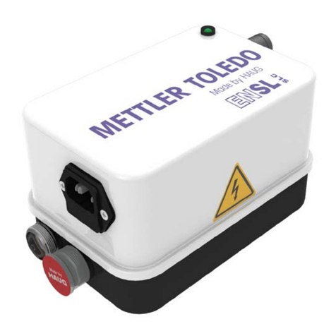
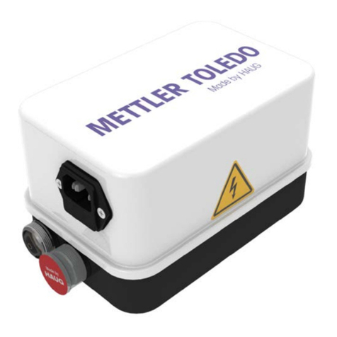
Haug EN 8 SLC MT User manual

Static Line
Operating instructions
Discharging power pack EN 8 SLC MT
Ident number: 01.7913.055 (100 V), 01.7913.005 (200 V),
01.7912.005 (230 V)
Keep for future use!
GB


Table of contents
1Operator instructions .................................................4
1.1 Symbols used in operating instructions ............................ 4
1.2 Symbols on the discharging power pack.......................... 5
2Safety ..........................................................................6
2.1 Intended use ..................................................................... 7
3Product overview........................................................8
4Install ..........................................................................9
5Operate .....................................................................13
5.1 Normal operation ............................................................ 13
5.2 Cyclic operation .............................................................. 13
6Troubleshooting .......................................................14
6.1 Replacing fuse................................................................. 15
6.2 Flow chart........................................................................ 16
7Accessories/spare parts ..........................................17
8Technical data ..........................................................18
8.1 Key figures and specifications......................................... 18
8.2 Supply voltage ................................................................ 18
8.3 Ambient conditions ......................................................... 19
8.4 Housing........................................................................... 20
9Taking out of operation ............................................21
9.1 Storing............................................................................. 21
9.2 Disposing ........................................................................ 21

1Operator instructions
4
1Operator instructions
Before installation and commissioning read these operating
instruction in full. Always observe the safety instructions.
These operating instruction is a part of the product; make sure you
retain them for later use or subsequent owners.
The discharging power pack is maintenance free and operationally
safe when used as intended.
The term “high voltage” is abbreviated HV in these operating
instructions (e.g. HV terminal).
The illustrations in this document are a simplified representation of
the product. They render only the technical facts and provide
support for the text. Departures from the actual product may be
noticeable. However, these deviations neither reduce the proper
function nor mitigate the specifications of the product.
1.1 Symbols used in operating instructions
Always observe this safety instruction to avoid critical or fatal injuries.
Always observe this safety instruction to avoid damage to property.
NOTE:
Important notes and additional information.

1Operator instructions
5
Never dispose of with household garbage.
Caution, danger spot warning!
1.2 Symbols on the discharging power pack
WARNING!
High voltage
ATTENTION!
Only plug in/unplug the ionizing unit at the HV
terminal when the discharging power pack is
switched off.

2Safety
6
2Safety
Only the persons authorized by the operator may carry out tasks on
the discharging power pack.
The installer must be a trained and qualified electrician and read the
operating instructions in full.
The operator must read the operating instructions in full.
When working on the discharging power pack, switch off the voltage
supply and secure against inadvertent switching on.
Hazards caused by manipulated or faulty discharging power
pack
Unauthorized modifications, moisture or damage to the discharging
power pack may result in electric shocks or fire hazards due to
sparking.
•
For reasons of safety, never open or modify the discharging
power pack.
•
In the event of visible damage or suspected electrical defects,
take the discharging power pack out of operation immediately
and secure against inadvertent reuse.
•
Protect the discharging power pack from moisture.
•
Never carry out any unauthorized repairs to the discharging
power pack.
•
Always switch off the discharging power pack after use.
•
Do not keep any inflammable materials in the vicinity of the
discharging power pack or its components.
Damage to device and risk of fire
Short circuits can occur
as a result of soiling in the high-
voltage (HV)
connection point. This can lead to faults with the
discharging power
pack and cause a fire.
•
The high-voltage connections and plugs must be clean, dry and
free of grease.
•
Use blind plugs to protect the unused HV connection points
against environmental influences. Ensure that the blind
plugs are
clean, dry and free of grease.
2Safety
7
2.1 Intended use
Risk of explosion!
The discharging power pack may generate sparks which ignite
gases, dust or similar substances.
•
Never install or use the discharging power pack in areas with
potentially explosive atmospheres.
The discharging power pack is intended exclusively for the supply of
alternating high voltage to HAUG ionizing units with X-2000
connector. In combination with an ionizing unit, electrostatic charges
are neutralized in a production process.
Always observe the installation and operating conditions indicated in
these operating instructions.
Warranty only covers products, accessories or spare parts of HAUG
GmbH & Co. KG.

4Install
9
4Install
Risk of explosion!
The discharging power pack may generate sparks which ignite
gases, dust or similar substances.
•
Never install or use the discharging power pack in areas with
potentially explosive atmospheres.
Electric shock hazard!
An electric shock hazard results from a faulty
connection of the
discharging power pack to the power supply.
•
The discharging power pack must only be installed by a trained
and qualified electrician.
Damage to equipment!
Continuous overloading of the discharging power pack may result in
failures.
•
Never exceed the permissible connected length.
•
Ne
ver install the discharging power pack on a surface generating
or radiating heat.
• Never install at a location subject to direct solar irradiation.
1. Check the model plate of the discharging power pack against the
ordering data. In the event of damage to the discharging power
pack, contact HAUG GmbH & Co. KG.
2. Before connecting the
cooling unit, ensure that the
correct supply voltage is
available for the
discharging power pack.
• The type plate attached
to the housing indicates the voltage.
• If the supply voltage is incorrect, the discharging power pack
may be damaged.

4Install
10
3. Place the discharging
power pack at the desired
place of use or attach it
using the enclosed retainer
plate.
• The position of the
discharging power pack
has does not affect its
function.
• We recommend
attaching the
discharging power pack
with the HV connections
facing downwards
(protection against
moisture, oil and dirt).
4. Make sure that the
discharging power pack is
switched off.
5. Connect the earthing
connection of the
discharging power pack to
the earth potential in
accordance with applicable
standards.
• The earthing cable must
be at least 1.5 mm2.

4Install
11
6. Connect the discharging
power pack to the supply
voltage. Always use the
supplied IEC power cord
with its integrated ground
wire.
• Plug in the IEC power
cord into the cold device connection of the discharging power
pack.
• Plug in the mains plug only to a socket with functioning
ground conductor.
Contact and separation spark-overs!
When the ionizing unit is plugged in or unplugged
while the
discharging power pack is switched on, spark
-overs will occur at the
HV connection. This may result in defects in the discharging power
pack.
•
Switch off discharging power pack before plugging in/unplugging
ionizing unit.
7. Connect the ionizing unit to
the HV terminal of the
discharging power pack.
• Insert the ionizing unit’s
HV plug in the HV
terminal of the
discharging power pack
and press the HV cable
until it reaches the stop.
• Screw the screw cap
onto the HV terminal and tighten by hand.
NOTE:
Protect unused HV terminals against the ingress of environmental
substances using the blind plugs. The blind plugs must be clean,
dry and all grease must be removed.

4Install
12
8. If necessary, connect the
signal line to the signal
socket.
• The discharging power
pack can be cycled via
the signal socket.
Configuration of the signal
socket:
A External control voltage
or
B External clock switch
Pin 1 External control
voltage (square
wave signal, 1 kHz,
10 V, positive)
Pin 2 0 V
Pin 3 not used
Pin 4 not used
Pin 5 Clock switch connection
Pin 6 Clock switch connection
PE Shield Ground/signal ground
NOTE:
The discharging power pack only supplies voltage if the signal line
is connected or the jumper plug is screwed on.
In order to avoid a malfunction while the signal line is connected,
only one time-relay control unit may be connected. Either connect
the external control voltage or the external clock switch.
9. The discharging power pack is ready for operation.

5Operate
13
5Operate
Preconditions:
The discharging power pack and the ionizing unit are connected and
installed as specified in the operator instructions.
5.1 Normal operation
There is no signal line connected to the signal socket. The jumper
plug must be connected to the signalling socket.
1. Use the power switch to turn on the discharging power pack.
• To verify this, the power switch is illuminated.
• The HV is switched on.
2. The indicator light is lit.
3. The discharging power pack is running.
4. If the operation fails, the indicator light turns off.
• In order to correct the malfunction, proceed with
troubleshooting the error. Refer page 14.
5.2 Cyclic operation
The signal line K6 is connected to the K6 signal socket of the
discharging power pack.
1. Use the power switch to turn on the discharging power pack.
• To verify this, the power switch is illuminated.
2. Use the signal line to switch on the HV.
• Close the external clock switch.
or
• Trigger via the control voltage.
3. When the HV is switched on, the indicator light illuminates.
4. The discharging power pack is running.
5. If the operation fails, the indicator light turns off.
• In order to correct the malfunction, proceed with
troubleshooting the error. Refer page 14.

6Troubleshooting
14
6Troubleshooting
Electric shock hazard!
The discharging power pack is operated electrically and generates a
high electric voltage. In the event of any faults, there is a
risk of an
electric shock.
•
Faults may only be eliminated by a trained and qualified
electrician.
NOTE:
If the error cannot be removed in this way, return the discharging
power pack and ionizing unit for checking to HAUG GmbH & Co. KG
(the address is provided on the back of the envelope).
Fault
Cause
Troubleshooting
Mains
switch
does not
illuminate.
Mains failure
Check mains fuse
Defective fuse in
discharging power
pack.
Check fuse in discharging power
pack.
Ionisation
not
available
No HV
Check connections in
discharging power pack.
Electrically
conductive
deposits on
ionizing unit.
Clean ionizing unit
Discharging power
pack is damaged.
Shut the discharging power pack
down immediately and secure
against switching on.
Signalling
lamp does
not
illuminate
during
operation.
The ionizing system
has a fault.
Perform work steps according to
the following flow chart. Refer
page 16..

6Troubleshooting
15
6.1 Replacing fuse
Damage to equipment!
An incorrect fuse in the discharging power pack may cause a defect.
This may result in a cable fire.
•
Only use fuses of the specified type.
•
Never use repaired fuses.
• Never bridge the fuse.
The unit type and the rated voltage are indicated on the nameplate.
1. Disconnect the discharging
power pack.
2. Determine and rectify the
reason for the fuse failure.
3. Use a screwdriver to
unscrew the fuse holder (C)
and remove it.
4. Replace the fuse and attach
the fuse holder again.
Only use the following fuse:
• 100 V = T500 mA L250; 5 x 20 mm
• 115 V = T500 mA L250; 5 x 20 mm
• 230 V = T250 mA L250; 5 x 20 mm

6Troubleshooting
16
6.2 Flow chart
The indicator lamp does not illuminate.
Discharging power
pack is faulty
Switch off discharging power pack and
unplug ionizing units.
Disconnect signalling line from
discharging power pack and screw
jumper plug onto the signalling socket.
Switch on the discharging power pack.
yes
Switch off discharging power pack and
connecting a ionizing unit.
Switch on the discharging power pack.
This ionizing unit
has a fault.
(Short circuit)
Ionizing system is ok
no
no
no
yes
yes
This ionizing unit
has a fault.
(Short circuit)
Switch off discharging power pack and
connecting another ionizing unit.
Switch on the discharging power pack.
Indicator lamp stays off?

7Accessories/spare parts
17
7Accessories/spare parts
The supplier of accessories and spare parts is the authorized local
sales agent of Mettler-Toledo.
Article
Order number
Point electrode
11107765
Optional second electrode
11107762
U-Electrode universal
11107764
U-Electrode small
11140161
Ionizing kit Quantos System
11141829
Mains cable (country-specific)
On request
Blind plug for HV terminals
On request

8Technical data
18
8Technical data
8.1 Key figures and specifications
Reference temperature 23 °C
HS connections
2
High voltage
6.7 ±1 kV~
Short-circuit current
I
k
≤5 mA
Square wave signal: Pulse width
Tp/To
Cycle in > 40 %
Cycle out < 1 %
Amplitude
10 V~ ±20 %
Frequency
1 kHz ±20 %
Polarity
Positive
8.2 Supply voltage
Unit type Rated value
Frequency
range
Power
consumption
01.7913.055
100 V~ ±10 %
50 - 60 Hz
P
max
= 80 VA
01.7913.005
115 V~ ±10 %
50 - 60 Hz
P
max
= 80 VA
01.7912.005
230 V~ ±10 %
50 - 60 Hz
P
max
= 80 VA

8Technical data
19
8.3 Ambient conditions
Never use in areas with
potentially explosive
atmospheres.
Must only be used indoors.
Height above mean seal level
to 2000 m
Temperature:
Rated application range
+5 to +45°C
Limit range for storage and
transport
-15 to +60°C
Relative humidity:
Rated application range
A = %RF
B = °C
Air pressure:
Rated application range
810 hPa to 1074 hPa
Vibrations:
Limit range for storage and
transport
max. 1.5 g (10 to 55 Hz), 1 h
Shock
max. 15 g in each direction

8Technical data
20
8.4 Housing
Protection type
IP 20
Protection class
I
Excess power category
II
Degree of pollution
2
Mains connection
via the IEC power cable
Dimensions:
Height
245 mm
Width
128 mm
Depth
125 mm
Weight:
5 kg
This manual suits for next models
3
Table of contents
Other Haug Power Pack manuals

Haug
Haug Multistat S User manual

Haug
Haug METTLER TOLEDO EN Series User manual

Haug
Haug EN 15 Ex User manual

Haug
Haug Static Line EN SL User manual

Haug
Haug Multistat Ex SDN User manual

Haug
Haug EN SL LC User manual

Haug
Haug 01.7835.300 User manual

Haug
Haug EN SL SLC MT User manual

Haug
Haug EN SL MT Series User manual

Haug
Haug EN 8 LC User manual