haupa 21 66 01 User manual

Q
ZERTIFIKAT
DIN EN ISO 9001
… convincing solutions
Electro hydraulic crimping tool
Art. 21 66 01
INSTRUCTION MANUALHydraulic pliers

1. Technical characteristics
Application field: A compression tool for crimping electrical connectors,
suitable for copper conductors up to 400 mm2and aluminium
conductors up to 300 mm2.
Force developed: 120 kN
Press opening: 25 mm
Rated operating pressure: 700 bar
Oil type: ISO class viscosity 15
Voltage 14.4V
Battery: 3.0 Ah
Speed of advance: The tool moves at two speeds. A speed to move the dies
together and a slower speed for the crimping action.
The changeover from one speed to the other is automatic.
Safety: The tool is equipped with a factory-set safety valve.
Sicherheitsventil ausgestattet.
Construction: 216601 model features a built-in drive pump.
It is equipped with an 180º rotating head for easy access in
confined areas. The model 216601 is not designed to protect the
operator in hot line work.
2. Working range
Pressure: 120 kN
Crimping range: DIN cable lugs 300 mm2
standard copper 400 mm2
aluminium 240 mm2
Crimping time: 6 - 12 sec.
Charging time for batteries: 20 min
Battery voltage: 14.4 V
Battery capacity: 3.0 Ah
Working pressure: 700 bar
Dimension: 335 x 310 x 75 mm
Weight: 7 kg
Weight Set: 12 kg

Germany: HAUPA GmbH & Co. KG, Königstraße 165-169, D -42853 Remscheid.
Phone: +49 (0)2191 8418-0, Fax: +49 (0)2191 8418-840, [email protected]om • Errors and technical changes reserved.
… convincing solutions
english
3. Instrucctions for use
WARNING! NEVER USE THE TOOL WITHOUT FIRST INSERTING THE DIE SET.
Ensure that the dies correspond exactly to the area to be crimped and that the dies are perfectly
positioned in their corresponding holders.
FAILURE TO DO SO COULD RESULT IN SERIOUS DAMAGE OR BREAKAGES AND WOULD VOID
THE GUARANTEE.
Preparation:
• Select the correct die for the connection to be made.
• Insert the die set in the tool head. All the dies used in these models are semicircular,
regardless of the type of compression or crimping to be performed. Both die parts have
identical outside dimensions and can therefore be mounted indistinctly on either the piston
or the head. The same procedure is used for mounting the dies on both the piston and the
head.
• Insert the die along the guides, until it comes to a stop against the locking pin.
• Then, remove the locking pin by pressing the release button and continue to insert the die
until it is retained in position by the pin.
• For the piston side: To carry out the above-mentioned operations, it is first necessary to
move the piston forward to allow access to the release button.
• Die removal: The procedure is also the same for both parts of the die set. Release by pres
sing the locking buttons and slide the die outwards. When removing the die from the
piston, reverse the procedure described in the previous point.
Die holder
Pushbutton
to advance
Pushbutton for
return movement

Start:
- Place the tool in the operating position
- Select the appropriate die for the connection to be made
- Insert the die set in the tool head
- Insert the conductor in the connector
- Place the connector between the two dies.
- Grip the tool and actuate the pushbutton to advance, the piston will rapidly advance
until the dies are in contact with the connector to be crimped.
- When the dies start to press the connector, the tool automatically changes from rapid
speed to crimping speed.
- Crimp until the audible sound of the pressure limiter release is heard, or until the two
dies touch.
- Rotate the release valve handle a quarter of a turn to the left and the piston will auto-
matically retract to its initial position or to the desired position.
4. Battery removal and installation
Hold the grip firmly and press the battery release button to remove it.
CAUTION
Never short circuit the battery
Battery installation
Insert the battery ensuring that the poles are correct.
Battery charging
Before using the tools, charge the battery as follows:
When you insert a battery into the charger, the battery will start to charge and the red pilot light
will be on continuously. Once the battery is completely charged, the red pilot light will flash (at
one second intervals).
Plug the charger cable into an AC socket.
Once the charger plug has been connected to the mains, the red pilot light will
light.

Germany: HAUPA GmbH & Co. KG, Königstraße 165-169, D -42853 Remscheid.
Phone: +49 (0)2191 8418-0, Fax: +49 (0)2191 8418-840, [email protected]om • Errors and technical changes reserved.
… convincing solutions
english
Insert the battery in the charger
Firmly insert the battery, in the direction indicated in the following figures, until it
comes into contact with the charger compartment bottom.
CAUTION
If the battery is inserted the wrong way round, apart from not charging this could also damage
the charger, such as the deformation of the charging terminal.
5. Care and maintenance
Cleaning
• Adequate cleaning of the tool after use, particularly the mobile parts, will help to
lengthen its useful life. Remember that dust, sand, environmental conditions –
particularly with a high salt index – and dirt in general are all extremely harmful to
hydraulic tooling.
• Particular care should be taken when cleaning both the pump drive piston and the
compression piston since any impurities could scratch the cylinder walls and damage
the leaktight seals. To clean the pistons correctly, in this case, we would recommend
advancing the piston and then cleaning it with a high quality non-corrosive solvent.
Power switch
Check that the machine switch is automatically released when you stop pressing it.
Should you detect any anomaly, replace it immediately.

Reservoir oil level
Ensure that the oil level is always above the black line on the viewer.
Do not fill the reservoir with noncompatible oil or brake fluid.
Oil type: VESTA HLP-15 manufactured by VERKOL or similar. Remove the reservoir cap and add oil to
the level marked. The oil must be filtered first. If necessary, any quantities you may
require could be supplied from our factory.
Storage
In order to prevent damage to the tools, caused by impact, dust etc, we would recommend
storing the tools in their carrying cases in a storage area.
Oil level
It is advisable to check the oil level in the tank at regular intervals, and particularly after
prolong use, and top up if necessary.
Oil top-up or filling procedure
This operation should only be performed by authorised technicians.
Important: the hydraulic oil must be filtered, have an ISO grade viscosity of 15,a viscosity index of
100 and conform to the AFNOR NFE 48603-HM and ISO 6743/4 L-HM standards.
CAUTION
To operate the tool correctly, the WORKING POSITION must be the natural one, that is with the hand-
le pointing downwards.
Turn off the cap and fill in
the oil on demand

Germany: HAUPA GmbH & Co. KG, Königstraße 165-169, D -42853 Remscheid.
Phone: +49 (0)2191 8418-0, Fax: +49 (0)2191 8418-840, [email protected]om • Errors and technical changes reserved.
… convincing solutions
english
6. Fault diagnostics
Before performing any work on the tool, ensure that it is disconnected from the mains.
ATTENTION:
If you should require any service other than those detailed below, please consult the nearest
Technical Service Centre.
PROBLEM
The tool does not advance,
advances slowly or
intermittently
The tool advances but
does not retain the
pressure
The tool does not retract,
partially retracts or does
so slower than normal
Loss of oil at the piston
POSSIBLE CAUSE
Oil level low
Release valve open
Loose quick connection
Load too big
Air in the system
Cylinder plunger jammed
Leak at the connections
Internal pump leak
Valve closed. Pump reservoir
excessively full
Loose connection
Air in the system
Interior hose Ø too narrow
Damaged cylinder spring or
the cylinder is damaged in
some other way
Broken o-rings
SOLUTION
Add oil in accordance with the instructions given above
Close the release valve
Check that all the connections are tight
Do not try to go above the rated load
Purge the air, keeping the pump higher than the
tool and operate it several times without increasing
the pressure
Check the cylinder for damage. Ask a mechanic
specialising in hydraulic systems to repair it
Check that all connections are tight and that there
are no leaks
Ask a mechanic specialising in hydraulic systems
to repair the pump
Open the release valve Remove all until it reaches the max line
shown on the viewer
Check that all connections are tight
Purge as indicated above
Use a hose with a larger diameter that supports an
operating pressure of 700 bar
Ask a mechanic specialising in hydraulic systems
to repair the pump
Have specialised personnel replace the o-rings.

Always use original spares. Any other part type could seriously damage the tool and void the guarantee.
If despite the above, the tool still does not work correctly, return it to the nearest Technical
Service for repair and fine tuning by specialised personnel or send an e-mail to:
WHEN ORDERING SPARES, ALWAYS PROVIDE THE FOLLOWING INFORMATION.
1. Item code number
2. Item description
3. Instruction manual reference and/or date
4. Tool type
5. Tool serial number
The guarantee will become void if spares other than the HAUPA original spares are used.
Spare parts list
No. Decription PU
1 PLASTIC BOX (L) 1
2 PLASTIC BOX (R) 1
3 UP PLASTIC CAP 1
4 BATTERY 14.4V 1
5 PUMP BODY 1
6 SCREW 2
7 SPRING 2
8 BALL CAP 2
9 BALL7.0 mm 2
10 SPRING 2
11 BALL 4.75 mm 4
12 SPRING 1
13 O RING 1
14 BACK-UP RING (P4) 1
15 SCREW 1
16 WASHER 1
17 VALVE BODY 1
18 SPRING 1
19 SPRING 2
20 BALL 4.0MM 3
21 SCREW 4
22 O RING 2
23 VALVE BASE 1
24 O RING 1
25 VALVE BODY 1
26 VALVE ROD 1
27 O RING 1
28 SPRING 1
29 PIN 1
30 BACK-UP RING (P8) 1
31 SPRING 1
32 O RING 1
33 PISTON 1
34 O RING 1
35 ROTATION ROD 1
36 O RING 1
37 RELEASE VALVE STEM 1
No. Decription PU
38 O RING 1
39 OIL RERSERVOIR 1
40 OIL RESERVOIR PLUG 1
41 SNAP RING 1
42 SPRING FIEXED PIECE 1
43 SPRING 1
44 AXEL 1
45 O RING 1
46 BACK-UP RING 1
47 PISTON 1
48 PIN 1
49 PISTON BUTTON 1
50 PLATE 1
51 PIN 1
52 SPRING 1
53 FIXED BUTTON 1
54 C-TYPE HEAD 1
55 SCREW 1
56 BALL 2
57 SPRING 2
58 SPRING BASE 2
59 NUT 2
60 -
61 -
62 -
63 -
64 SNAP RING 1
65 SCREW 1
66 ALUM-HEAD 1
67 RELEASE 1
68 NUT 1
69 SCREW 1
70 MONITOR 1
71 SCREW 1
72 SCREW 4
73 BEARING 2
74 ROTATION ROD 1
No. Decription PU
75 BEARING 1
76 BEARING BASE 1
77 FIRST GEAR BASE 1
78 FIRST GEAR PART 4
79 RING GEAR 2
80 RUBBER WASHER 1
81 SECOND GEAR BASE 1
82 SECOND GEAR PART 4
83 WASHER 1
84 GEAR BOX CAP 1
85 SCREW 2
86 MOTOR FIXED PIECE 1
87 SCREW 4
88 GEAR 1
89 MOTOR 1
90 LOCK RING 1
91 PROTECT CAP 1
92 MONITOR 1
93 SCREW 2
94 RELAY 1
95 OVER LOAD BREAKER 1
96 SPRING 2
97 PLASTIC FIXED PIECE 1
98 SCREW 4
99 FLYING RING 2
100 PROTECT CAP 1
101 SWEACH 1
102 SWEACH PIN 1
103 SPRING 1
104 SWEACH 1
105 SCREW 2
106 INSULATE PLATE 1
107 LOCK PLATE 2
108 CONDUCTION PLATE 2
109 SCREW 1
110 SCREW 1
111 SCREW 5
112 SCREW 2
Germany: HAUPA GmbH & Co. KG, Königstraße 165-169, D -42853 Remscheid.
Phone: +49 (0)2191 8418-0, Fax: +49 (0)2191 8418-840, [email protected]om • Errors and technical changes reserved.
… convincing solutions
english
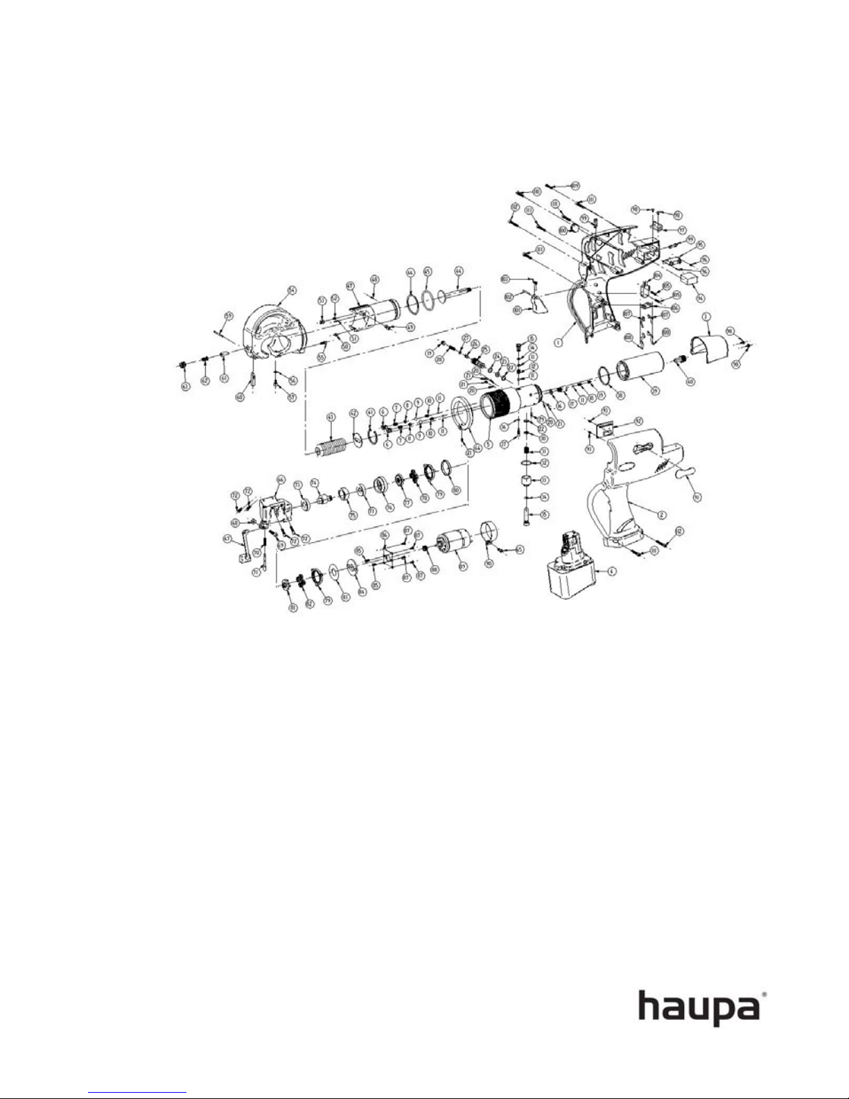
Exploded assembly drawing Art. 21 66 01
Table of contents
Other haupa Crimping Tools manuals

haupa
haupa AO-6 User manual

haupa
haupa KH-12 User manual

haupa
haupa MO-6 User manual

haupa
haupa SMART-LINE 216801-1 User manual

haupa
haupa SD300-6M User manual

haupa
haupa AC25-12 User manual

haupa
haupa SMART-LINE SH-6 User manual

haupa
haupa SMART-LINE SO-6M User manual

haupa
haupa SMART-LINE SH-6 User manual

haupa
haupa SDE240-6M User manual


Popular Crimping Tools manuals by other brands

Tyco Electronics
Tyco Electronics PIDG Series instruction sheet

ZURN
ZURN Medium QickClamp Operation instructions

Tyco Electronics
Tyco Electronics AMP CERTI-CRIMP II instruction sheet

Staubli
Staubli PV-CZM-61100 operating instructions

molex
molex CR5905 Operating Instruction and Specifications Sheet

Textron
Textron Greenlee GATOR EK1550FLX Operation manual


