haupa SMART-LINE SH-6 User manual
Q
ZERTIFIKAT
DIN EN ISO 9001
… convincing solutions
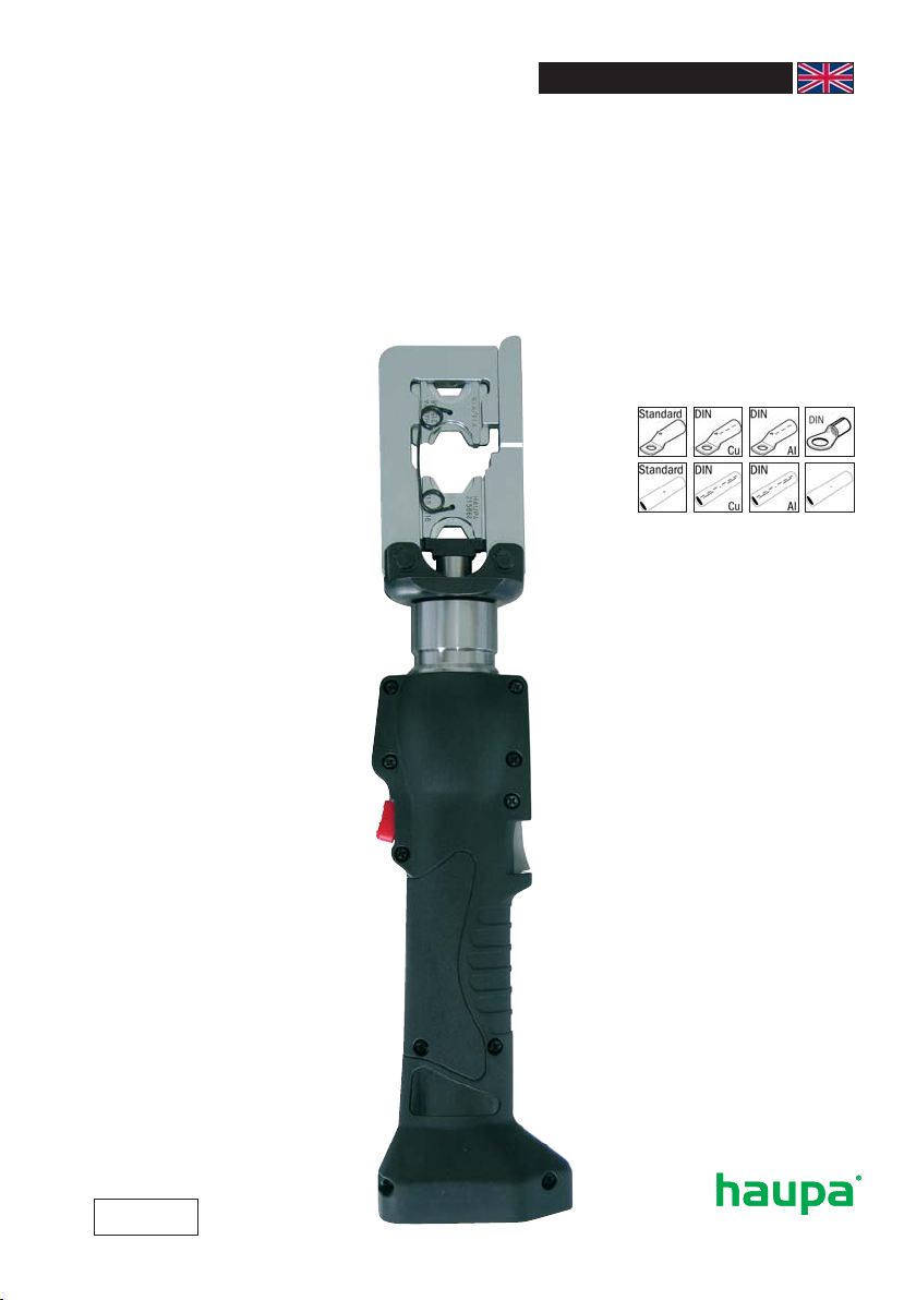
Battery powered crimping tool
„SH-6“
Art. 21 58 81
INSTRUCTION MANUALBattery powered crimping tool SMART-LINE

1. Technical data
Area of application: For the creation of an electrical connection by means of
compression
Scope of delivery: 1 crimping tool, 1 charger, 2 batteries, 1 carry loop, in plastic case,
without pressing dies.
Pressing force: 60kN
Oil type: ISO class viscosity 15
Safety: The tool is fitted with a safety value that has been set at the factory.
Structure: The working head can be rotated by 180° to make it easier to adapt
to the operation to be carried out. The model Art. 215881 does not
protect the operator when working on cables that carry power.
Guarantee: 2 year guarantee if used for the purpose it is intended
2. Area of work/Performance characteristics
• Pressing force in kN: 60kN
• Working pressure in bar: 700
• Head can be opened
• Opening / Hub: 9 mm
• Pressing width: slim
• Motorstop
• Crimping range cable lugs: Cu 10-240 / DIN Cu 10-240 / DIN Al 16-185
• Crimping range connectors: Cu 10-240 / DIN Cu 10-240 / DIN Al 16-185
• Pressing time, battery-operated in seconds: 2
• Battery charging time in minutes: 60
• Battery type: NiMH, 14,4 V, 3 Ah
• Weight in kg: 2,4
• Weight Set in kg: 3,2
• 6 tonnes of pressing force for maximum performance
• Motor stop. The feed is stopped immediately the operating switch is released.
No post-travel of the piston
• 180° rotating crimping head. Can thus be mounted even in places that are difficult to
access
• Manual return enables shorter process cycles and saves battery capacity
• The manual return enables the operator to bring the piston back to the starting point in
the event of a faulty pressing.
• After the pressing is completed, the device operates in idle.
(If the compression is not completed, manual return of the piston on the return operation
button is „very perceptibly“ more difficult)
• The two button operation ensures logical, simple and quick single-handed operation.
• The tool is supplied with 2 NiMH batteries, 3 Ah and a quick charger.
• The second battery ensures continuous operation.
(One battery in use, the other in the charger)

Germany: HAUPA GmbH & Co. KG, Königstraße 165-169, D - 42853 Remscheid.
Phone: +49 (0)2191 8418-0, Fax: +49 (0)2191 8418-840, [email protected] • Errors and technical changes reserved.
… convincing solutions
english
3. Operating instructions
CAUTION! TOOLS MAY NEVER BE USED WITHOUT FIRST INSERTING THE PRESSING DIES.
Ensure that the pressing dies fit precisely to the appropriate area and are seated perfectly in
the holders.
OTHERWISE THIS MAY CAUSE SERIOUS DAMAGES OR BREAKAGES AND THE GUARANTEE WILL
BE VOIDED.
Preparation
Before starting up the tool, read the operating instructions first.
All current-carrying elements in the area you are working in should be disconnected.
Otherwise the protective procedures for working in the vicinity of components under current
must be implemented. (DIN EN 50110)
Do not use the tool if you are tired or under the influence of medication, drugs or alcohol.
Take into account the valid accident prevention and safety regulations and use the tool exclusi-
vely for the purpose for which it is intended.
Only electro-technically trained persons over 16 years of age may process connecting materials
using the tool.
The operating instructions must always be carried with the tool.
The instructions must have been read and understood by the user.
The operator must ensure that this is the case.
• Pressing dies from 10 to 120 mm2can be used on both sides (2 conductor cross-sections
with only one pressing die)
• Area of application in accordance with the available pressing dies (max. 240 mm2DIN tube
terminals)
Operating:
• Select the required pressing die.
• Never use a crimping tool without pressing dies!
• The pressing procedure can be stopped at any time by releasing the actuation switch.
• No components under power may be compressed.
• The tool is not insulated!
• The tool is not designed for permanent use.
• After 35 - 45 compression actions carried out one after another, you must take a break
of 10 to 15 minutes to allow the tool to cool down.
• If it is heated too high, this may cause damages to the tool.
• Do not use under water or when it is raining.
• Please observe the processing notes for the relevant connection materials as detailed in
our catalogue.
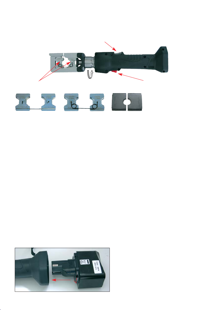
4. Removing and inserting the battery
Never short-circuit the battery.
ATTENTION:
Hold the tool firmly and press the battery release button to remove the battery.
Inserting the battery
Insert the battery until it clicks into place. Make sure the poles are facing the right way.
Die holder Pushbutton for return movement
Pushbutton to advance
Illustration 1
Germany: HAUPA GmbH & Co. KG, Königstraße 165-169, D- 42853 Remscheid.
Phone: +49 (0)2191 8418-0, Fax: +49 (0)2191 8418-840, [email protected] • Errors and technical changes reserved.
… convincing solutions
english
Charging
Before using the tool, charge the battery as follows:
Connect the cable of the charger to a socket (AC).
As soon as the charger is connected to the power supply, the red LED will light up.
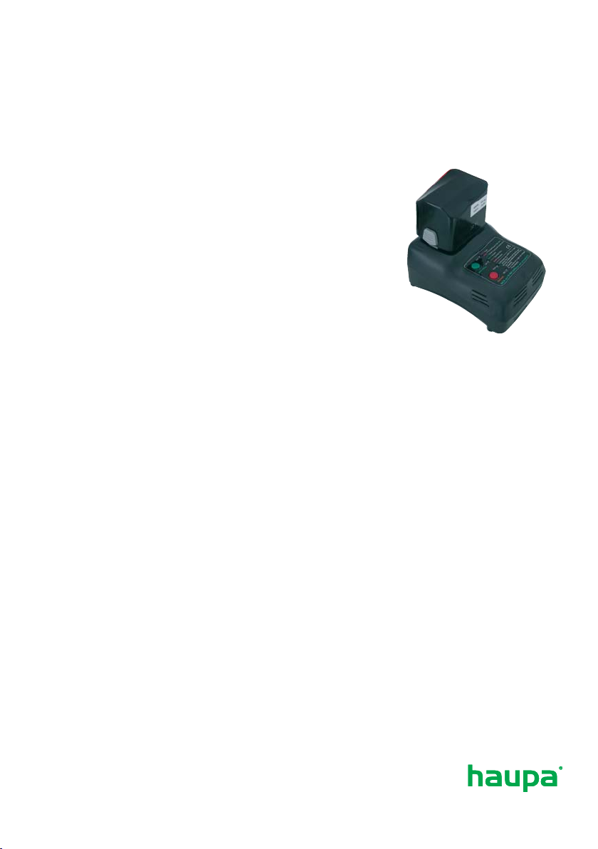
Inserting the battery into the charger
Insert the battery firmly, as shown in Illustration 2 shown here,
until it touches the bottom of the charging compartment.
ATTENTION:
If the battery is inserted incorrectly (Illustration 1),
it will not only not be charged, it may also damage the charger
(e.g. by bending the terminals/short-circuiting).
Charging
When you insert a battery into the charger, the battery will start charging and the green control
light will also light up.
When the battery is fully charged the green control light will flash.
If the yellow control light comes on, the battery is overheating. Remove the battery immediately
and disconnect the charger from the power supply.
5. Care and maintenance
Cleaning
• Careful cleaning of the tool, in particular, the moving parts contributes towards a longer use-
ful life. Remember that dust, sand, environmental influences, in particular a high salt index, and
dirt in general are extremely damaging to hydraulic tools.
• Particular care should be taken when cleaning the pump drive piston and the piston.
The tiniest of contaminations may scratch the walls of the cylinder and damage the leak-proof
seals. For the correct cleaning of the piston, we recommend extending the piston and then
cleaning it with a high-quality, non-corrosive solution.
Power switch
Check to see whether the switch on the machine automatically pops out again when you
release it.
Storage
To prevent damage to the tool as a result of bumps, dust etc. you should if possible store the
tools in the original packaging.
Illustration 2

Guarantee:
2 year guarantee when used for the purpose it is intended when the annual maintenance inter-
vals are maintained by an authorised HAUPA service centre.
We reserve the right to rework the product.
Faults:
Loss of oil:
Send to the HAUPA service centre. Do not open!
Very slow feed of the piston:
Air is in the hydraulic system. Keep the head upright and operate both operating switches for
10 seconds at the same time in idle. As soon as the air has been expelled from the hydraulic
system, the feed rate and the pressure is restored.
Disposal:
…in accordance with the scope of validity of the European WEEE (2002/96/EU) and RoHS
directives (2002/95/EU). Batteries must be disposed off separating according to the battery
directive.

Germany: HAUPA GmbH & Co. KG, Königstraße 165-169, D- 42853 Remscheid.
Phone: +49 (0)2191 8418-0, Fax: +49 (0)2191 8418-840, [email protected] • Errors and technical changes reserved.
… convincing solutions
english
Always use original replacement parts. Other parts may seriously damage the tool and will void
the guarantee.
If the tool still does not work correctly, send it to the nearest repair service for specialist main-
WITH EVERY REPLACEMENT PART ORDER, INCLUDE THE FOLLOWING INFORMATION:
1) Article number.
2) Article description.
3) Reference to the operating instructions and/or date.
4) Tool type.
5) Serial number of the tool.
The guarantee is voided if you use parts that are not original replacement parts from HAUPA.
Replacement parts list art. 215881
N0. Description PU
1 Housing (R) 1
2 Housing (L) 1
3 Start Knob 1
4 Spring 1
5 Switch Rod 1
6 Release Lever 1
7 Lever Support 2
8 Switch Unit 1
9 Release Spring 1
10 M4 x 12Screw 6
11 M4 x 20Screw 4
12 Strap 1
13 Power System 1
14 S-32 O-Ring 1
15 Oil Reservoir 1
16 S-36 O-Ring 1
17 Bush 1
18 1/8" Steel Ball 1
19 M4 x4 Screw 1
20 Cylinder Insert 2
21 P06 Back-Up Ring 2
22 PS-6 O-Ring 2
23 Pump Piston 2
24 Piston Spring 2
25 Release Valve Stem 1
26 P03 O-Ring 2
27 Reservoir Screw 1
28 S3 O-Ring 1
29 Filter Seat 2
31 Suction Valve 2
N0. Description PU
32 P03 O-Ring 2
33 5/32" Steel Ball 3
34 Valve Spring 2
35 M3X5 Screw 1
36 Release Spring 1
37 P03 Back-Up Ring 1
38 Release Screw 1
39 Safety Valve Set 1
40 P05 O-Ring 1
41 3/16" Steel Ball 2
42 Valve Spring 2
43 Valve Seat 2
44 Screw 1
45 Pump Body 1
46 P-28 O-Ring 1
47 P-28 Back-Up Ring 1
48 Ram 1
49 Ram Spring 1
50 Cylinder Head 1
51 Pin 2
52 Snap Ring 4
53 M5 x5 Screw 1
54 M5 x8 Screw 1
55 Die Holder 1
56 Jaw 2
57 Spring 1
58 Upper Die Holder 1
59 Spring 2
60 Down Die Holder 1
61 M4 x3 Screw 1
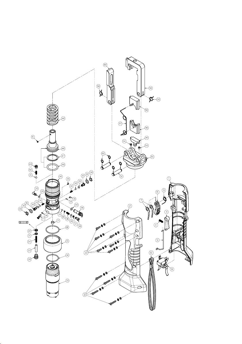
Exploded assembly drawing art. 215881
Other manuals for SMART-LINE SH-6
1
Table of contents
Other haupa Crimping Tools manuals

haupa
haupa SHs-6M User manual

haupa
haupa AC25-12 User manual

haupa
haupa SMART-LINE SHs-6 User manual

haupa
haupa SMART-LINE SH-6 User manual

haupa
haupa KH-12 User manual

haupa
haupa SMART-LINE 216801-1 User manual

haupa
haupa AO-6 User manual

haupa
haupa US-6M User manual

haupa
haupa 21 67 50 User manual

haupa
haupa SD300-6M User manual


