manuals.online logo
Brands
  1. Home
  2. •
  3. Brands
  4. •
  5. Tyco Electronics
  6. •
  7. Crimping Tools
  8. •
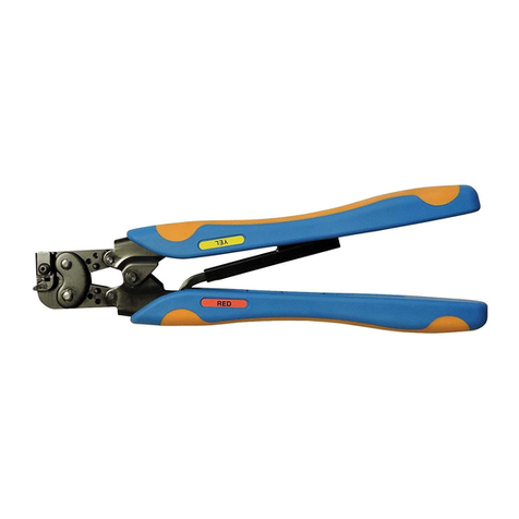
  9. Tyco Electronics PIDG Series User manual

Tyco Electronics PIDG Series User manual

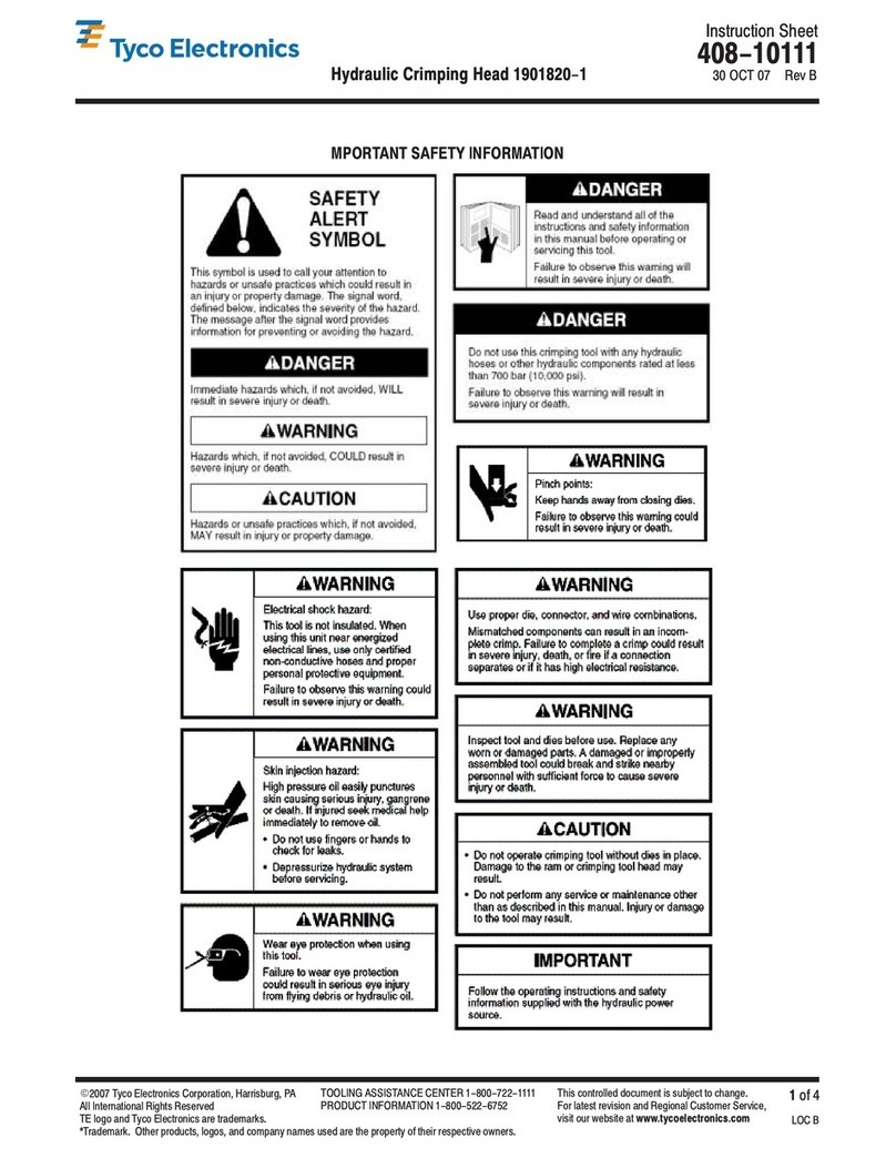
Instruction Sheet
Premium RBY Die Set and Locator
Assembly for PIDG* and PLAS I-GRIP* 408-10256
LOC B
1
of 4
E
2008 Tyco Electronics Corporation, Harrisburg, PA
All International ights eserved
TE logo and Tyco Electronics are trademarks.
*Trademark. Other products, logos, and company names used are the property of their respective owners.
TOOLING ASSISTANCE CENTE 1-800-722-1111
P ODUCT INFO MATION 1-800-522-6752 This controlled document is subject to change.
For latest revision and egional Customer Service,
visit our website at
www.tycoelectronics.com
27 OCT 08 ev A
Red / Blue / Yellow erminals
PROPER USE GUIDELINES
CumulativeTraumaDisorderscanresult fromtheprolongeduseofmanuallypoweredhand tools.Handtoolsareintendedforoccasional useandlowvolume
applications. A wide selection of powered application equipment for extended-use, production operations is available.
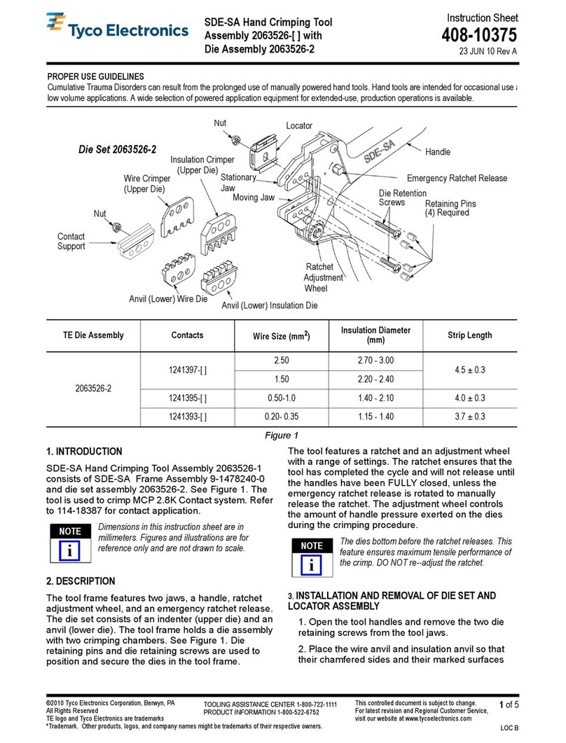
Die Assembly 2063030-1
( eplaceable Item)
Hand Tool Frame Assembly
9-1478240-0 ( ef)
ERMINAL/S RIP LENG H INFORMA ION
PRODUC WIRE SIZE INSULA ION INSULA ION S RIP LENG H
LINE RANGE, AWG DIAME ER (MAX.) COLOR MINIMUM MAXIMUM
PIDG or
22-16 3.56 [.140] ed 5.15 [.203] 5.95 [.234]
PIDG or
PLASTI-G IP
Til
16-14 4.32 [.170] Blue 5.15 [.203] 5.95 [.234]
Terminals 12-10 6.35 [.250] Yellow 7.94 [.312] 8.73 [.344]
PIDG FASTON* 22-18 Flag 3.56 [.140] ed 8.33 [.328] 9.14 [.360]
Terminals 16-14 Flag 4.32 [.170] Blue 8.33 [.328] 9.14 [.360]
Figure 1
1. IN RODUC ION
This instruction sheet provides application and
maintenance procedures for the Premium RBY Die
Set and Locator Assembly 2063030–1 for PIDG and
PLASTI–GRIP Red / Blue / Yellow Terminals. See
Figure 1.
The die set is designed to crimp PIDG and
PLASTI–GRIP terminals onto pre–stripped wire.
Read these instructions thoroughly before crimping
any terminals.
All dimensions are in millimeters [with inches in
brackets]. Figures and illustrations are for
reference only and are not drawn to scale.
NO E
i
408-10256
Premium RBY Die Set an Locator Assembly
Rev
A2
of 4 Tyco Electronics Corporation
Figure 2
Typical PIDG
Type Terminal
Insulation
Stripped Wire
Enters From
Back of Tool
Front of Tool
Back of Tool
Yellow
Red
Blue
Wire Crimper
Insulation Crimper
Die Set
2063030-1
Locator
Assembly
Ed e of Terminal
Insulation Ali ned
with Locator
Flat Side of
Terminal
2. DESCRIPTION
(Fi ure 1)
The die set is a replaceable die assembly with three
crimping areas which are marked with the letters R,B,
and Y. The letter corresponds to the insulation color of
the terminal (Red, Blue, or Yellow) to be crimped in
the crimping area. This die set can be used in the
tools listed in Figure 4. Refer to the instructions
packaged with the tools for die installation/removal
and tool operation procedures.
3. CRIMPING PROCEDURE
(Fi ure 2)
1. Strip wire to proper length. See Figure 1.
2. Choose desired terminal and match insulation
color to crimping area letter.
3. Place terminal in the appropriate crimping
chamber between the locator assembly and the
upper die. Make sure that the flat side of the
terminal faces up. See Figure 2.
4. Terminal should be positioned in tool so that
wire enters from the BACK of the tool.
5. Close tool handles until terminal is held in dies
without deforming wire barrel.
6. Place stripped wire in terminal wire barrel and
squeeze handles until ratchet releases.
Damaged terminals may not be used. If a
terminal has been damaged during termination,
it must be cut from the wire and replaced with a
new one.
4. MAINTENANCE AND INSPECTION
4.1. Daily Maintenance
It is recommended that operators of the die set be
made aware of, and responsible for, the following
steps of daily maintenance:
1. Remove dust, moisture, and any other
contaminants from the die with a clean, soft brush,
or a clean, soft, lint–free cloth. Do NOT use hard or
abrasive objects that could damage the die.
2. Make certain that the retaining pins are in place
and that they are secured with retaining rings.
3. All pins, pivot points, and bearing surfaces
should be protected with a thin coat of any good
SAE 20 motor oil. Do not oil excessively.
4. When the tool is not in use, keep handles closed
to prevent objects from becoming lodged in the
crimping jaws. Store the tool in a clean, dry area.
CAUTION
!
408-10256
Premium RBY Die Set and Locator Assem ly
3
of 4Rev
A
Tyco Electronics Corporation
4.2. Periodic Inspection
Regular inspections of the die should be performed by
quality control personnel. A record of scheduled
inspections should remain with the die or be supplied
to supervisory personnel responsible for the die.
Inspection frequency should be based upon amount
of use, working conditions, operator training and skill,
and established company standards.
4.3. Visual Inspection
1. Remove all lubrication and accumulated film by
immersing the tool (handles partially closed) in a
suitable commercial degreaser that will not affect
paint or plastic material.
2. Make certain that all retaining pins are in place
and secured with retaining rings.
3. Close tool handles until ratchet releases and
then allow them to open freely. If they do not open
quickly and fully, the spring is defective and must
be replaced. Refer to the instructions packaged
with the tool.
4. Inspect the tool frame for wear or damage,
paying particular attention to the tool jaws and
pivot points. If damage is evident, refer to the
instructions packaged with the tool for replacement
of parts. If tool is acceptable, lubricate and return
to service.
5. Check the crimping dies occasionally to make
sure dies are not broken or chipped. If damage is
evident, refer to Paragraph 6, PARTS
REPLACEMENT.
5. MEASURING DIE OPENING
The die assembly will perform correctly as long as:
S
The product specified is correct for the
application.
S
The specific die assembly is used.
S
The die assembly has been measured to
ensure that the openings are correct.
S
The tool has been adjusted correctly.
Figure 3 provides information on die opening sizes.
Figure 3
4.37 +0.08
[.172 +.003] 2.84 +0.08
[.112 +.003]
3.10 +0.08
[.122 +.003]
6. PARTS REPLACEMENT
Customer–replaceable parts are shown in Figure 1. If
the dies are damaged or worn excessively, they must
be replaced. Order the replaceable parts through your
Tyco Electronics Representative, or call
1–800–526–5142, or send a facsimile of your
purchase order to 1–717–986–7605, or write to:
CUSTOMER SERVICE (38–35)
TYCO ELECTRONICS CORPORATION
P.O. BOX 3608
HARRISBURG, PA 17105–3608
For tool repair service, please contact a
representative at 1–800–526–5136.
7. REVISION SUMMARY
S
Initial release of document
408-10256
Premium RBY Die Set and Locator Assembl
Rev
A4
of 4 Tyco Electronics Corporation
Figure 4
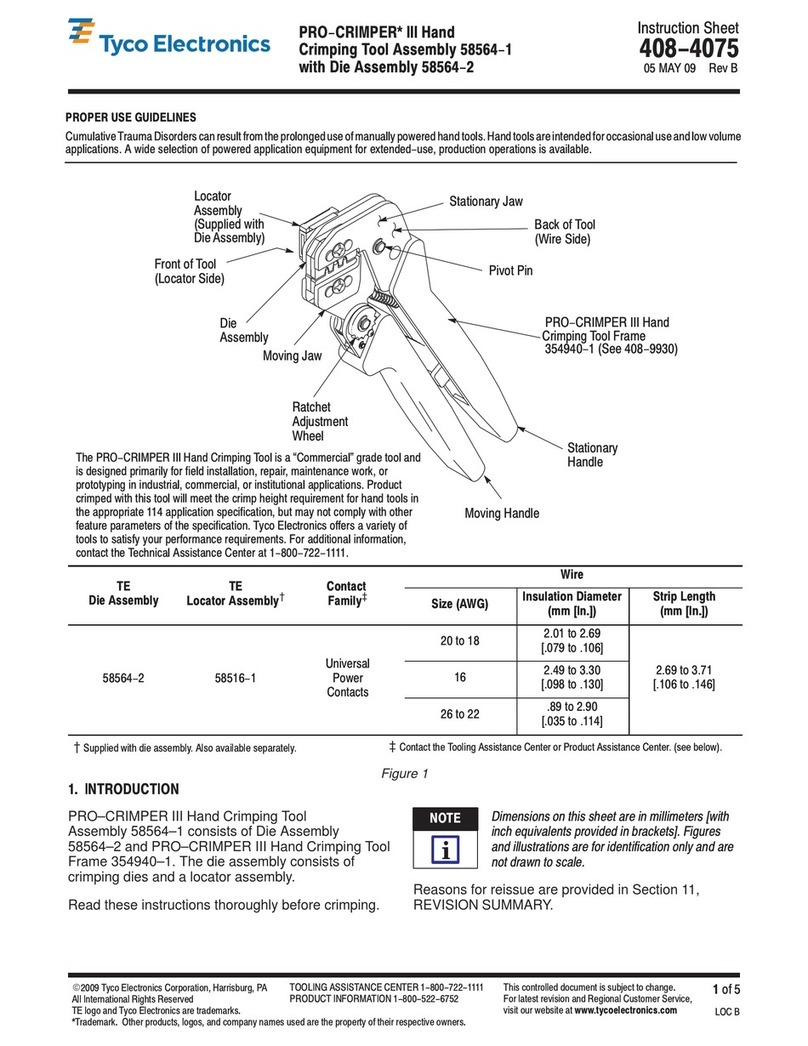
Pro-Crimper Hand Tool 354940-1
(Instru tion Sheet 408-9930) SDE PEW-12 Hand Tool 9-1478240-0
(Instru tion Sheet 408-8851)
SDE Ben h Terminator 1490076-2
(Customer Manual 409-10052) 626 Adapter 679304-1
(Instru tion Sheet 408-4070)
Battery Tool (Shouldered Die) 1725837-1, -2
(Customer Manual 409-10053) Battery Tool (Pin Die) 1213890-1, -2
(Customer Manual 409-10065)
Die Set and Lo ator Assembly 2063030-1 Can be Used in Tools Show Below

This manual suits for next models

2

Other Tyco Electronics Crimping Tools manuals

Tyco Electronics 2063195-1 User manual

Tyco Electronics

Tyco Electronics 2063195-1 User manual

Tyco Electronics 58613-1 User manual

Tyco Electronics

Tyco Electronics 58613-1 User manual

Tyco Electronics 48858-1 User manual

Tyco Electronics

Tyco Electronics 48858-1 User manual

Tyco Electronics PRO-CRIMPER II User manual

Tyco Electronics

Tyco Electronics PRO-CRIMPER II User manual

Tyco Electronics PRO-CRIMPER III User manual
Tyco Electronics

Tyco Electronics PRO-CRIMPER III User manual

Tyco Electronics PRO-CRIMPER III User manual

Tyco Electronics

Tyco Electronics PRO-CRIMPER III User manual

Tyco Electronics STRATO-THERM 1-46673-0 User manual

Tyco Electronics

Tyco Electronics STRATO-THERM 1-46673-0 User manual

Tyco Electronics 3-1579002-1 User manual

Tyco Electronics

Tyco Electronics 3-1579002-1 User manual

Tyco Electronics ERGOCRIMP 3-1579001-5 User manual

Tyco Electronics

Tyco Electronics ERGOCRIMP 3-1579001-5 User manual

Tyco Electronics PRO-CRIMPER III User manual

Tyco Electronics

Tyco Electronics PRO-CRIMPER III User manual

Tyco Electronics 603995 Series User manual

Tyco Electronics

Tyco Electronics 603995 Series User manual

Tyco Electronics 9-1478246-0 User manual

Tyco Electronics

Tyco Electronics 9-1478246-0 User manual

Tyco Electronics PRO-CRIMPER III 58564-1 User manual

Tyco Electronics

Tyco Electronics PRO-CRIMPER III 58564-1 User manual

Tyco Electronics 2-1579004-9 User manual

Tyco Electronics

Tyco Electronics 2-1579004-9 User manual

Tyco Electronics 46121 User manual

Tyco Electronics

Tyco Electronics 46121 User manual

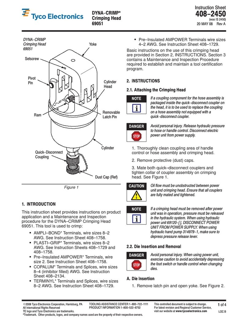
Tyco Electronics 1901820-1 User manual

Tyco Electronics

Tyco Electronics 1901820-1 User manual

Tyco Electronics 58569-1 User manual

Tyco Electronics

Tyco Electronics 58569-1 User manual

Tyco Electronics CERTI-CRIMP II User manual

Tyco Electronics

Tyco Electronics CERTI-CRIMP II User manual

Tyco Electronics PRO-CRIMPER III 58517 Series User manual

Tyco Electronics

Tyco Electronics PRO-CRIMPER III 58517 Series User manual

Tyco Electronics 1213850-1 User manual

Tyco Electronics

Tyco Electronics 1213850-1 User manual

Tyco Electronics PRO-CRIMPER III User manual

Tyco Electronics

Tyco Electronics PRO-CRIMPER III User manual

Tyco Electronics AMP PRO–CRIMPER II User manual
Tyco Electronics

Tyco Electronics AMP PRO–CRIMPER II User manual

Tyco Electronics PIDG STRATO-THERM 1-576778-0 User manual

Tyco Electronics

Tyco Electronics PIDG STRATO-THERM 1-576778-0 User manual

Tyco Electronics PRO-CRIMPER III User manual
Tyco Electronics

Tyco Electronics PRO-CRIMPER III User manual

Popular Crimping Tools manuals by other brands

CRH CRL CBLHCT1 instruction manual

CRH

CRH CRL CBLHCT1 instruction manual

Staubli PV-CZM operating instructions

Staubli

Staubli PV-CZM operating instructions

Cembre B540ND-BVE Operation and maintenance manual

Cembre

Cembre B540ND-BVE Operation and maintenance manual

Hasco Z 865 Series operating instructions

Hasco

Hasco Z 865 Series operating instructions

KUDOS HD-BGD3 SAFETY OPERATING & MAINTENANCE INSTRUCTIONS

KUDOS

KUDOS HD-BGD3 SAFETY OPERATING & MAINTENANCE INSTRUCTIONS

Cembre B1350-CA Operation instructions

Cembre

Cembre B1350-CA Operation instructions

Textron Klauke ERB0818-L instruction manual

Textron

Textron Klauke ERB0818-L instruction manual

molex 207129 Series Specification sheet

molex

molex 207129 Series Specification sheet

BARTON TOOLS EC300 instruction manual

BARTON TOOLS

BARTON TOOLS EC300 instruction manual

molex 63819-3700 manual

molex

molex 63819-3700 manual

molex 63825-6070 Specification sheet

molex

molex 63825-6070 Specification sheet

Elpress V611 Directions for use

Elpress

Elpress V611 Directions for use

HYDROSCAND H120BASIC user manual

HYDROSCAND

HYDROSCAND H120BASIC user manual

Burndy HYTOOL MD6 Series SAFETY OPERATING & MAINTENANCE INSTRUCTIONS

Burndy

Burndy HYTOOL MD6 Series SAFETY OPERATING & MAINTENANCE INSTRUCTIONS

Panduit Black Fin CT-2931 Series instruction manual

Panduit

Panduit Black Fin CT-2931 Series instruction manual

Trick-tools Roper Whitney 0585 Operation, parts & maintenance manual

Trick-tools

Trick-tools Roper Whitney 0585 Operation, parts & maintenance manual

TE Connectivity 2393700-1 instruction sheet

TE Connectivity

TE Connectivity 2393700-1 instruction sheet

molex 64001-2800 Operating Instruction Sheet And Specifications

molex

molex 64001-2800 Operating Instruction Sheet And Specifications

manuals.online logo
manuals.online logoBrands
  • About & Mission
  • Contact us
  • Privacy Policy
  • Terms and Conditions

Copyright 2025 Manuals.Online. All Rights Reserved.