USE ONLY HAYWARD GENUINE REPLACEMENT PARTS
EAU129IOM Rev B ECR 044V
Page 3 of 6
Hayward Flow Control
1-888-HAY-INDL (1-888-429-4635) www.haywardowcontrol.com
• These actuators are designed to be used between a horizontal and upright position. Do NOT mount
the assembly with the actuator top below a horizontal position (i.e. upside down).
• When installing conduit, use proper techniques for entry into the actuator. Use drip loops to prevent
conduit condensate from entering the actuator.
• The EMT conduit port MUST use proper ttings to protect the NEMA 4X integrity of the housing.
• Use proper wire size to prevent actuator failure (see Wire Sizing Chart for proper wire sizing).
• All terminals accept 12-18AWG solid/stranded wire.
CAUTION – Please follow the following guidelines for proper installation.
1. Fully OPEN the valve to which the actuator is to be mounted.
2. Assemble necessary linkage hardware and attach the actuator to the valve.
3. Center the actuator on the valve drive shaft and tighten all hardware.
4. Make the electrical connections per the Wiring Diagram.
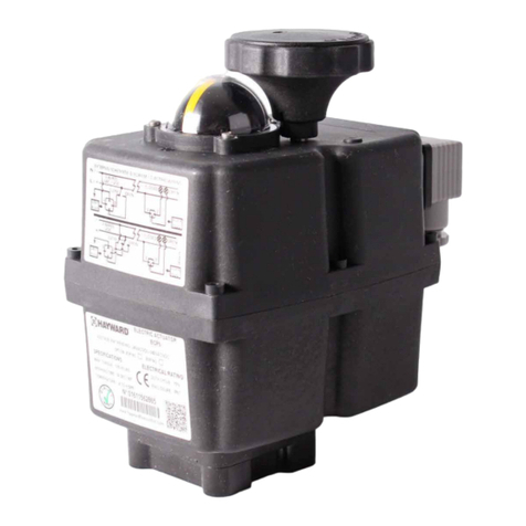
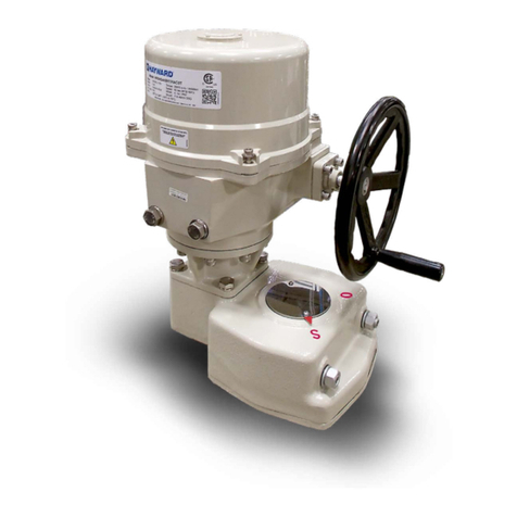
Position Indication - The coupling
is visible between the actuator and
the mounted valve, allowing the
user to see the position of the valve.
2 PB
Hayward is a registered trademark
of Hayward Industries, Inc.
© 2018 Hayward Industries, Inc.
USA: 1.888.429.4635 • Fax: 1.888.778.8410 • One Hayward Industrial Drive • Clemmons, NC 27012 • Email: [email protected] Canada: 1.888.238.7665 • Fax: 1.905.829.3636 • 2880 Plymouth Drive • Oakville, ON L6H 5R4 • Email: [email protected] Visit us at: haywardflowcontrol.com
TECHNICAL INFORMATION, CONTINUED
EAU1 Series
Electronic Actuators
NPP_EAU1
VALVE SELECTION CHART
SIZE
IN/DN TRUE UNION BALL VALVE THREE-WAY BALL VALVE
1/2”-2” / 15-50 EAU129 (90°) N/A
WIRING DIAGRAM
CCW
Rotation seen from below is a mirror
of the direction viewed from above.
1. Position on arrival:
• An unmounted actuator is delivered in the OPEN position which also
means the auxiliary switch is closed between terminals 6 and 7. (For
proper position and indication, mount this actuator to your valve with the
valve and actuator in the open position).
• A 2 way ball valve assembly arrives in the FULLY OPEN (CCW) position.
2. Storage: This unit should not be stored outside unless it is powered up and
has proper conduit terminations. When not powered up, it should be stored
in a clean, dry environment at all times.
3. This quarter-turn actuator has been factory tested for operation between 0°
and 90°. There are no travel adjustments.
4. Notice: The EAU129 Series actuators have no mechanical stops to limit rotation.
5. Notice: Protect the actuator from moisture by installing it with water tight
EMT ttings and proper conduit drainage. There is no internal heater.
WARNING – To avoid dangerous or fatal electrical shock, turn OFF power to all electrical equipment
before working on electrical connections.
Notice: All EAU129 Series actuators rotate CCW to close the output
shaft out the bottom of the actuator when viewed from above. The
actuator is unidirectional and rotates 90° with each control signal input.
ACTUATOR HANDLING AND INSTALLATION
PRODUCT MOUNTING AND SETUP
SHIPPING AND HANDLING
INSTALLATION NOTES
Back to TOC
