Installation:
This light should be installed at least 152mm (6”) below the water line by qualified/approved personnel using proper tools and
materials. The minimum hull thickness is 8mm (0.31”) and maximum (for sufficient heat dissipation) is 73mm (2.87”) with an
access area of at least 100mm (3.9”) left behind the light for LED array servicing and general ventilation.
After selecting a flat surface, cut a 60mm (2-3/8”) diameter hole through the vessel hull in the desired location. Caution! Check
that no electrical wiring, fuel lines, oil lines, water lines etc., pass near or through the intended hole location.
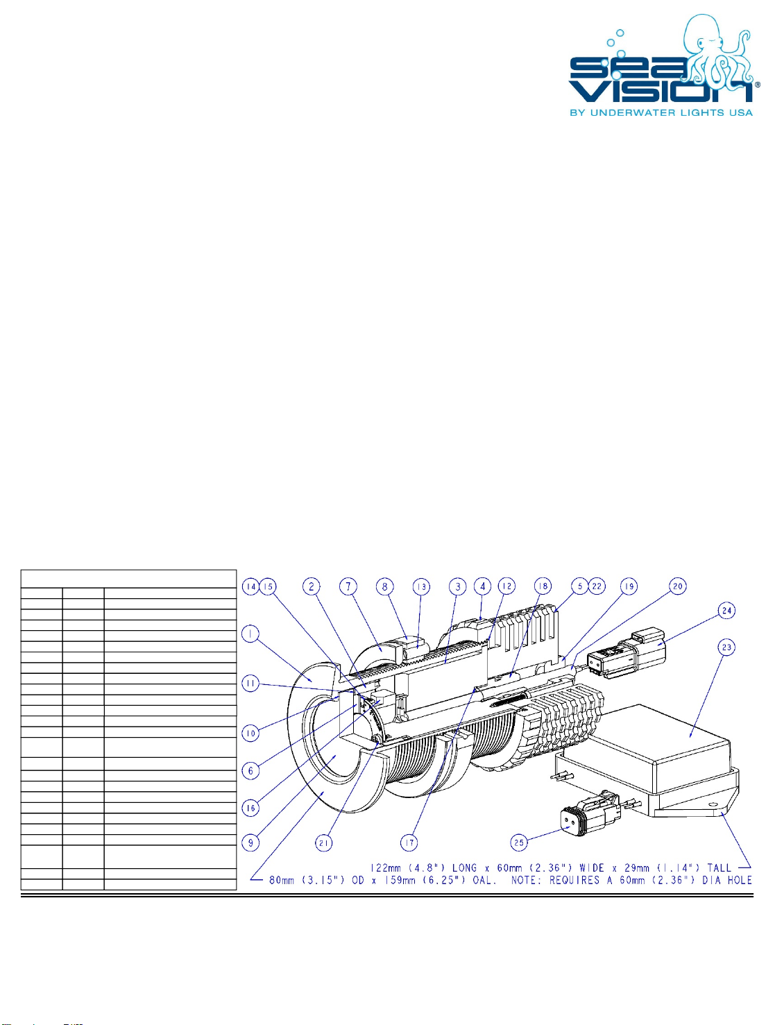
Remove numbers (4) [with attached (5)], (7) + (8) from the light. Carefully coat the Flanged Main Body (1) and inner surface of
above cut hole with 3M 5200 Marine Adhesive or equivalent. Caution! Avoid placing adhesive on flanged main body threads. Note:
Exposed inner hole surface must be properly sealed before light installation to prevent potential water intrusion into the hull proper.
Holding the Flanged Main Body (1), push the light through the hole, slide the Compression Ring (7) over the Flanged Main Body (1)
and then tighten the Locking Ring (8) hand tight. Note: Ensure that the tips of all three set screws (13) are NOT touching the
Compression ring (7). After the 3M 5200 Marine Adhesive is fully cured, tighten the three set screws (13) to 7 Nm (5 ft/bs) using a
3mm allen wrench.
Insert the Projector Mount (3) in the Flanged Main Body (1) and hand tighten Projector Lid (4) [with attached (5)]. Upon
completing light installation, it is highly recommended that the Flanged Main Body (1) face be coated with antifouling paint and a
wire lead be connected from the Locking Ring (8) M4 x 0.7 tapped hole to the vessels grounding and cathodic protection system.
Securely mount the LED Driver (23) as high as possible away from the light and point electrical wires downwards. Connect loose
LED driver RED wire lead to a switched and fused power source utilizing supplied fuse, connect loose LED driver BLACK wire lead to
a good ground. Plug LED driver (25) output connector to LED light input connector (24).
Caution! Directly connecting power source to light without using the LED driver will permanently damage the light.
Serviceable Parts:
The SV20 LED Underwater Light is field serviceable and most of the parts are replaceable. However, numbers (9), (10) + (11) are
not field serviceable on this light. Please contact our technical support staff to discuss your individual needs.
Underwater Lights Europe Sarl
16, rue Rouaze
06400 Cannes, France
Phone: 33-(0)-4-97-21-02-96
Fax: 33-(0)-4-97-21-10-96
Internet: www.seavision.com
Underwater Lights USA, LLC
3406 SW 26th Terrace, C-6/7
Fort Lauderdale, FL 33312USA
Phone: 1-954-760-4447
Fax: 1-954-525-3261 Internet:
www.seavision.com Email:
Thru-Hull Mount, LED Array
SV20 LED
Underwater Light
WHITE MODELS A11A11B41-13G32C-36, 12VDC & A11A11B41-14G32C-36, 24VDC
BLUE MODELS A11A11B49-13G32C-36, 12VDC & A11A11B49-14G32C-36, 24VDC
CABLE STRAIN RELIEF2011018
STRAIN RELIEF O-RING2010917
THERMOSWITCH2010816
WHITE LED ARRAY
BLUE LED ARRAY
20106
20121
14
M6 x 1.0 x 16LG SST SET SCREW2002113
PROJECTOR LID GASKET2001612
OUTER GLASS GASKET2004610
GLASS200459
LOCKING RING200118
COMPRESSION RING200107
LED SHIELD201056
PROJECTOR CAP201045
PROJECTOR LID201034
PROJECTOR MOUNT201013
GLASS RETAINING COLLAR200422
FLANGED MAIN BODY200391
DESCRIPTIONPARTBALLOON
12VDC LED DRIVER COMPLETE
24VDC LED DRIVER COMPLETE
20116
20117
23
RUBBER GROMMET2011119
INNER GLASS GASKET2004811
LED ARRAY CONNECTOR2010715
ELECTRICAL CABLE2011220
M3 x 0.5 x 5LG SST PPHS2011321
M3 x 0.5 x 20LG SST SHCS2011422
RECEPTACLE ASSEMBLY, 2-WAY2011824
PLUG ASSEMBLY, 2-WAY2011925