HBM MP60 User manual

A0616-13.4 en
PME industrial
measurement electronics
with fieldbus link
MP60/MP07
Operating manual


3
PME-MP60/MP07
A0616-13.4 en HBM
Contents Page
Safety instructions 4. . . . . . . . . . . . . . . . . . . . . . . . . . . . . . . . . . . . . . . . . . . . .
1 Introduction 9. . . . . . . . . . . . . . . . . . . . . . . . . . . . . . . . . . . . . . . . . . . . . . . . .
1.1 Scope of supply and accessories 9. . . . . . . . . . . . . . . . . . . . . . . . . . .
1.2 General 9. . . . . . . . . . . . . . . . . . . . . . . . . . . . . . . . . . . . . . . . . . . . . . . . .
2 Selecting amplifier settings with DIP switches 11. . . . . . . . . . . . . . . . .
3 Mounting/dismounting the MP60/MP07 15. . . . . . . . . . . . . . . . . . . . . . . .
3.1 Connecting several modules 17. . . . . . . . . . . . . . . . . . . . . . . . . . . . . . .
4 Connections 18. . . . . . . . . . . . . . . . . . . . . . . . . . . . . . . . . . . . . . . . . . . . . . . .
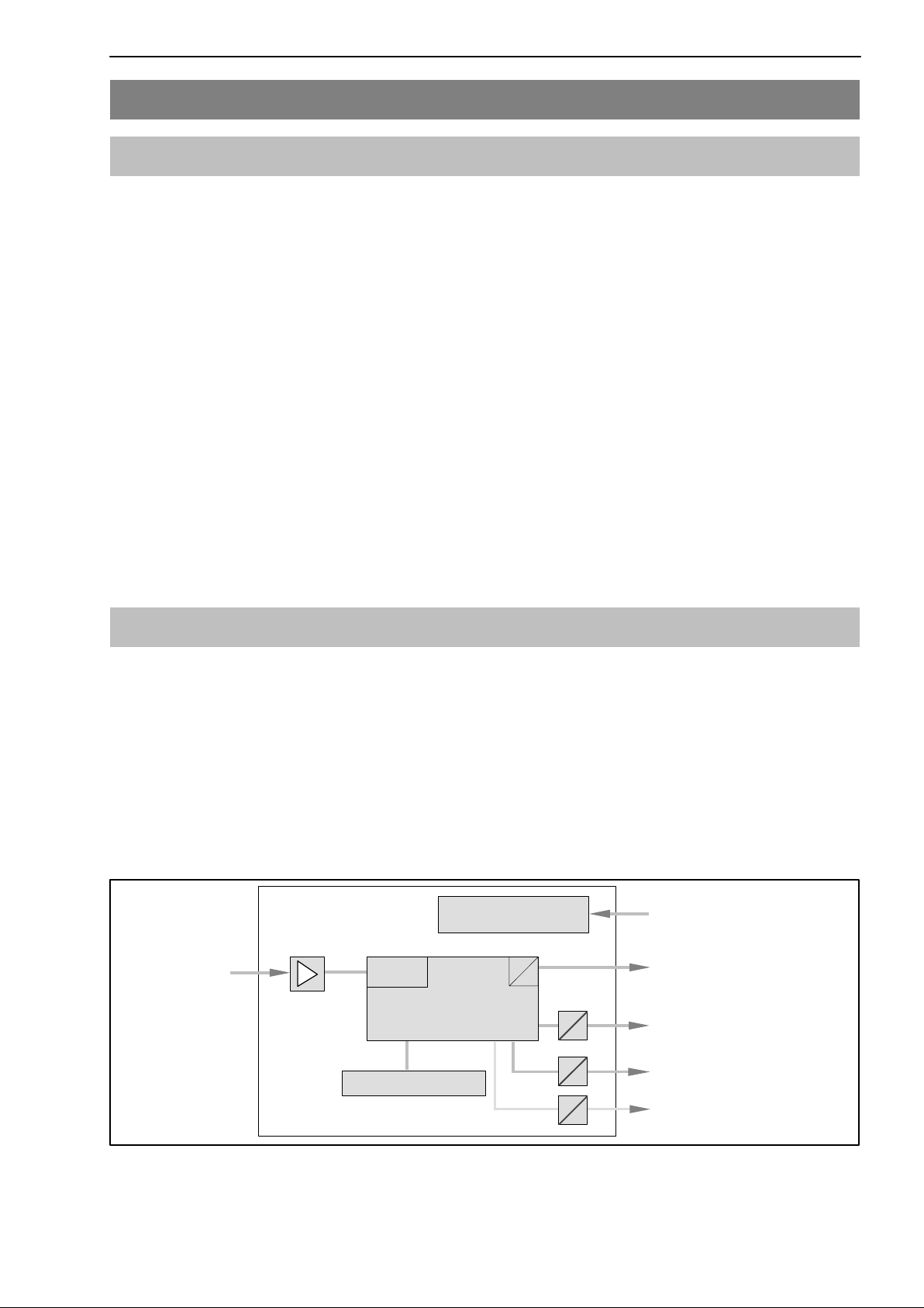
4.1 Functional overview of MP60/MP07 18. . . . . . . . . . . . . . . . . . . . . . . . .
4.2 Supply voltage and control inputs/outputs MP60 19. . . . . . . . . . . . . .
4.2.1 External supply voltage for control outputs (MP60) 20. . . . . . .
4.3 Supply voltage MP07 21. . . . . . . . . . . . . . . . . . . . . . . . . . . . . . . . . . . . .
4.4 Connecting a transducer 22. . . . . . . . . . . . . . . . . . . . . . . . . . . . . . . . . .
4.5 CAN interface 25. . . . . . . . . . . . . . . . . . . . . . . . . . . . . . . . . . . . . . . . . . . .
4.6 Synchronization (MP60) 26. . . . . . . . . . . . . . . . . . . . . . . . . . . . . . . . . . .
5 Setting up and operation (MP60) 27. . . . . . . . . . . . . . . . . . . . . . . . . . . . . .
5.1 Operating principles 27. . . . . . . . . . . . . . . . . . . . . . . . . . . . . . . . . . . . . .
5.2 Commissioning 30. . . . . . . . . . . . . . . . . . . . . . . . . . . . . . . . . . . . . . . . . . .
5.3 Guide to all groups and parameters 31. . . . . . . . . . . . . . . . . . . . . . . . .
5.3.1 Set up all parameters 32. . . . . . . . . . . . . . . . . . . . . . . . . . . . . . . .
5.4 Example: measuring Md and N with torque
transducer T10F (24 V supply) 36. . . . . . . . . . . . . . . . . . . . . . . . . . . . .
6 Declaring the significant parameters 39. . . . . . . . . . . . . . . . . . . . . . . . . .
7 CAN interface description (MP60 only) 47. . . . . . . . . . . . . . . . . . . . . . . .
7.1 General 47. . . . . . . . . . . . . . . . . . . . . . . . . . . . . . . . . . . . . . . . . . . . . . . . .
7.2 Cyclical data transmission 47. . . . . . . . . . . . . . . . . . . . . . . . . . . . . . . . .
7.3 Parameter assignment 48. . . . . . . . . . . . . . . . . . . . . . . . . . . . . . . . . . . .
7.4 Object directory (communications profile section) 50. . . . . . . . . . . . .
7.5 Emergency objects 53. . . . . . . . . . . . . . . . . . . . . . . . . . . . . . . . . . . . . . .
7.6 Object directory: manufacturer-specific objects 54. . . . . . . . . . . . . . .
7.7 Manufacturer-specific objects in floating data format 64. . . . . . . . . .
7.8 Examples 66. . . . . . . . . . . . . . . . . . . . . . . . . . . . . . . . . . . . . . . . . . . . . . .
8 Error messages/operating status (LED) 67. . . . . . . . . . . . . . . . . . . . . . .
9 Keyword index 72. . . . . . . . . . . . . . . . . . . . . . . . . . . . . . . . . . . . . . . . . . . . . .

4PME-MP60/MP07
A0616-13.4 enHBM
Safety instructions
Before connecting the device, make sure that the mains voltage and current
type specified on the type plate correspond to the mains voltage and current
type at the site of installation and that the current circuit used is sufficiently
safe.
Due to the fact that the device has not been equipped with a proper
mains switch, the connected supply cable must not be directly
connected to the mains. The maximum permissible supply voltage is
18...30 V.
According to a VDE recommendation these devices must be equipped
with a switching device (e.g. with a mains switch) for disconnection
from the mains. Make sure, that the device can quickly be disconnected
from the mains at any time.
The supply connection, as well as the signal and sense leads, must be
installed in such a way that electromagnetic interference does not adversely
affect device functionality (HBM recommendation: ”Greenline shielding
design”, downloadable from the Internet at http://www.hbm.com/Greenline).
Automation equipment and devices must be covered over in such a way that
adequate protection or locking against unintentional actuation is provided
(such as access checks, password protection, etc.).
When devices are working in a network, these networks must be designed in
such a way that malfunctions in individual nodes can be detected and shut
down.
Safety precautions must be taken both in terms of hardware and software, so
that a line break or other interruptions to signal transmission, such as via the
bus interfaces, do not cause undefined states or loss of data in the
automation device.

5
PME-MP60/MP07
A0616-13.4 en HBM
Use in accordance with the regulations
The MP60 and MP07 module and their connected transducers may be used
for measurement tasks only and directly related control tasks. To ensure safe
operation, the transducer may only be used as specified in the operating
manual. It is also essential to follow the respective legal and safety
regulations for the application concerned during use. The same applies to the
use of accessories.
Each time, before starting up the equipment, you must first run a project
planning and risk analysis that takes into account all the safety aspects of
automation technology. This particularly concerns personal and machine
protection.
Additional safety precautions must be taken in plants where malfunctions
could cause major damage, loss of data or even personal injury. In the event
of a fault, these precautions establish safe operating conditions.
This can be done, for example, by mechanical interlocking, error signaling,
limit value switches, etc.
General dangers of failing to follow the safety instructions
The modules complies with the state of the art and is safe to operate. If the
equipment is used and operated inappropriately by untrained personnel,
residual dangers may arise.
Anyone responsible for installing, starting up, maintaining or repairing the
equipment needs to have read and understood the operating manual and in
particular the safety instructions.
Conditions on site
Protect the devices from moisture or atmospheric influences such as rain,
snow, etc.
Protect the device from direct sunlight. Ensure sufficient ventilation.
Maintenance and cleaning
The modules are maintenance free. Please note the following points when
cleaning the housing:
- Before cleaning, disconnect the devices from the power supply.
- Clean the housing with a soft, slightly damp (not wet!) cloth. You should
never use solvent, since this could damage the labelling on the front panel
and the display.
- When cleaning, ensure that no liquid gets into the device or connections.

6PME-MP60/MP07
A0616-13.4 enHBM
Residual dangers
The scope of performance and supply of the MP60 or MP07 covers only part
of the measurement technology. In addition, equipment planners, installers
and operators should plan, implement and respond to the safety engineering
considerations of measurement technology in such a way as to minimize re-
sidual dangers. Prevailing regulations must be complied with at all times. Re-
sidual dangers connected with measurement technology need to be pointed
out.
Any risk of residual dangers when working with the MP60 or MP07 is pointed
out in this introduction by means of the following symbols:
Symbol: WARNING
Meaning: Dangerous situation
Warns of a potentially dangerous situation in which failure to comply with sa-
fety requirements can result in death or serious bodily injury.
Symbol: CAUTION
Meaning: Potentially dangerous situation
Warns of a potentially dangerous situation in which failure to comply with
safety requirements could result in damage to property or some form of
bodily injury.
Symbol: NOTE
Points out that important information about the product or its handling is being
given.
Symbol:
Meaning: Statutory marking requirements for waste disposal
National and local regulations regarding the protection of the environment and
recycling of raw materials require old equipment to be separated from regular
domestic waste for disposal.
For more detailed information on disposal, please contact the local authorities
or the dealer from whom you purchased the product.

7
PME-MP60/MP07
A0616-13.4 en HBM
Symbol:
Meaning: CE mark
The CE mark enables the manufacturer to guarantee that the product com-
plies with the requirements of the relevant EC directives (the declaration of
conformity is available at http://www.hbm.com/HBMdoc).
Working safely
Error messages should only be acknowledged once the cause of the error is
removed and no further danger exists.
The device complies with the safety requirements of DIN EN 61010 Part 1
(VDE 0411 Part 1).
The device must be mounted on a support rail connected to grounded con-
ductor potential. Both the support rail and the MP60/MP60DP module must be
free of paint, varnish and dirt at the point of installation.
To ensure adequate immunity from interference, the bus cables (CAN and for
MP60DP, Profibus DP) must be shielded, twisted−pair lines. The transducer
cables must also be shielded. To ensure adequate immunity from interfer-
ence, use Greenline shielding only (conncect the shield of the transducer
cable to the plug housing).
The cables of the digital inputs and outputs of the MP60/MP60DP should not
be longer than 30 m or should they be routed outside the building where the
system is located. Otherwise proper functioning of the device cannot be guar-
anteed. The effects of strong electromagnetic fields or lightning strike could
result in damage to the instrument.
When connecting cables (fitting and extracting terminals), measures must be
taken to prevent electrostatic discharge which could damage the electronics.
The MP60/MP60DP module needs to be operated with a separated extra−low
voltage (18...30 V DC supply voltage), which usually supplies one or more
consumers within a control cabinet.
Should the equipment be operated on a dc voltage network1), additional pre-
cautions must be taken to discharge excess voltages.
1) Distribution system for electrical energy with greater physical expansion (over several control cabinets, for
example) that may possibly also supply consumers with high nominal (rated) currents.

8PME-MP60/MP07
A0616-13.4 enHBM
Conversions and modifications
HBM’s express consent is required for modifications affecting the transdu-
cers’s design and safety. HBM does not take responsibility for damage resul-
ting from unauthorized modifications.
The product is delivered from the factory with a fixed hardware and software
configuration. Changes can only be made within the possibilities documented
in the manuals.
The product is delivered from the factory with a fixed hardware and software
configuration. Changes can only be made within the possibilities documented
in the manuals.
Qualified personnel
The equipment may be used by qualified personnel only; the specifications
and the special safety regulationsneed to be followed in all cases.
This means people who meet at least one of the three following requirements:
−Knowledge of the safety concepts of automation technology is a
requirement and as project personnel, you must be familiar with these
concepts.
−As automation plant operating personnel, you have been instructed how to
handle the machinery and are familiar with the operation of the equipment
and technologies described in this documentation.
−As commissioning engineers or service engineers, you have successfully
completed the training to qualify you to repair the automation systems.
You are also authorized to activate, to ground and label circuits and
equipment in accordance with safety engineering standards.
It is also essential to comply with the appropriate legal and safety regulations
for the application concerned during use. The same applies to the use of ac-
cessories.
Qualified personnel means personel familiar with the installation, fitting,
start−up and operation of the product, and trained according to their job.

9
PME-MP60/MP07
A0616-13.4 en HBM
1 Introduction
1.1 Scope of supply and accessories
Scope of supply:
D1 MP60 module or 1 MP07 module
DFor the MP60: 3 x 6-pin terminal plugs, coded
Order No.: 3.3312−0427 (terminal plug 3);
3.3312−0428 (terminal plug 4); 3.3312−0426 (terminal plug 1)
D1 flat ribbon cable connector, 10-pin
DAdditional spring for assembly of housing (enclosed in bag)
D1 operating manual for MP60/MP07 module
DFor the MP07: shielded MP60-MP07 connector cable,
Order no.: 2-9269.0226
Accessories:
DStandard ribbon cable, 10pin, 1.27 mm pitch
1.2 General
MP60 module:
The MP60 module, from the PME product line, is a frequency measurement
module intended for connecting incremental transducers, frequency
generators and HBM T10F-SF1 and T10F-SU2 torque flanges.
The MP60 module is set up and parameters assigned via the keyboard and
display or with the aid of the PME Assistent. The PME Assistent gives you a
simple operator interface under MS-Windows for assigning parameters to the
modules (described in the ”PME Assistent” online help).
Keyboard and display
Voltage supply
electrically isolated 24 V
μPDA
Counter
Intelligent signal
conditioning,
e.g. limit value switch
MP60 / MP60DP
Scalable
Analogue output
Control inputs
Control outputs
Frequency outputs
CANopen interface
Profibus DP interface
(for MP60DP)
F1
F2
Zero reference
Error
Fig. 1.1: Block diagram of MP60 module

10 PME-MP60/MP07
A0616-13.4 enHBM
Note: You must set amplifier type MP60 on DIP switch S12 (MP60)
(see also page 13).
12 3456
S12
ON
Switch positions
must not be
changed!
Module MP07:
The MP07 module is used for the excitation of torque transducers.
The following HBM torque transducers may derive their excitation from an
MP07 module:
T10F-KF1, T30FNA, T32FNA, T34FN, T36FN
The MP07 module, like the MP60, is connected to a 24 V supply voltage and
delivers the following output voltages (short-circuit proof):
+15 VDC, 100 mA
-15 VDC, 100 mA
54 VPP / 75 VPP
, 150 mA (24 - 25 kHz square-wave excitation voltage)
The supply voltage is electrically isolated from the calibration signal inputs.
The calibration signal is triggered by increasing the excitation voltage of the
transducer shaft from 54 VPP to approx. 75 VPP 1).
The MP07 module has no display and no control keys.
1) See operating manual for torque transducer

11
PME-MP60/MP07
A0616-13.4 en HBM
2 Selecting amplifier settings with DIP switches
NOTE
The adjustment/alteration of DIP switch settings must take place before
mounting the PME.
Various settings are defined with the aid of DIP switches. These are the
settings for
terminating resistance, frequency input signals, input connection
(asymmetric, symmetric), analogue output, synchronization, bus
terminating impedance, slope steepness
To set the DIP switches, you must proceed as shown in Fig. 2.1.
S5
S4
S10
S11
S12
Screw off
cover
1
2
S6
Fig. 2.1: Open housing, position of DIP switch
123456
Example:
means
ON
Fig. 2.2: Switch convention

12 PME-MP60/MP07
A0616-13.4 enHBM
ON
ON
ON
Top
motherboard:
Bottom
circuit board:
S10
S11
123456123456
ON
123456
S10 S11 S12
ON ON
S6
S5
S12
1
2
3
123
ON
S4
1
2
3
5
4
6
1
2
3
5
4
6
1
2
3
5
4
6
ON ON ON
1
2
3
4
5
6
1
2
3
Synchronization
(Master)
Analogue
output
(10 V)
Analogue
output
(10 V)
Terminating
resistance
120 Ω
(OFF)
123 123456
ON ON
S6 S5
Switch positions
must not be
changed!
Amplifier
type
S10, S11, S12 and
S13
S4, S5 and S6
Factory settings:
Frequency
source, Zero
reference;
Internal switching
threshold
(Symmetric)
No
function
No
function

13
PME-MP60/MP07
A0616-13.4 en HBM
S11
S5
S6
S12 S4
123
ON
S6
Line terminating resistance 120W
Frequency source F1
123
ON
123
ON
Input signal asymmetric / symmetric2)
Factory settings:
Frequency source F2
Zero reference
123456
ON
Frequency source F1
123456
ON
Frequency source F2
123456
ON
Zero reference
S5
Analogue output1)
123456
ON
S11
123
ON
S4
"10 V
"20 mA
123456
ON
123
ON
123456
ON
4 - 20 mA
V
mA S4
S11
S11
ON
123
S6
123
ON
123
ON
123
ON
123
ON
123456
ON
symmetric asymmetric
123456
ON
123456
ON
symmetric asymmetric
OffOn
OffOn
OffOn
Fig. 2.3: Setting up the amplifier
1) Viewing/checking display under the ANALOGUE OUTPUT group, parameter ”Mode Vo”; see page 33
2) dependent on transducer
3) Connect (F1, F2 zero reference to ON) for symmetrical output signals and long measuring leads
(u100 m).

15
PME-MP60/MP07
A0616-13.4 en HBM
3 Mounting/dismounting the MP60/MP07
Fig. 3.1: Mounting on a support rail
Fig. 3.2: Dismounting

16 PME-MP60/MP07
A0616-13.4 enHBM
Fig. 3.3: Fitting of a second spring fore more stable mounting of the module on the
DIN rail
CAUTION
The support rail must be on protection circuit potential .

17
PME-MP60/MP07
A0616-13.4 en HBM
3.1 Connecting several modules
1.
2.
3.
Colour coding
at Pin 1
Flat ribbon cable connector
Recommended
spacing of flat ribbon
cable connectors
Subsequent devices are
interconnected via this connector.
58mm
Fig. 3.4: Connecting the flat ribbon cable
Several MP60 or MP07 modules may be connected over one flat ribbon
cable. This cable is used for local connection of the supply voltage and
synchronization between the modules. You should not interconnect more than
8 modules with one flat ribbon cable.
Connect MP60 to MP07
MP60 MP07
Flat ribbon cable,
Product number 171
(see Accessories)
MP60 MP07
Transducer shaft
Shielded MP60-MP07 connector cable, Order no.: 2-9269.0226
Fig. 3.5: Connect MP60 and MP07 with shielded cable

18 PME-MP60/MP07
A0616-13.4 enHBM
4 Connections
WARNING
Please take note of the safety instructions before putting the device into
operation.
4.1 Functional overview of MP60/MP07
Terminal plug 1:
Voltage supply and CAN-bus, Synchronization
Transducer connection (15-pin D-Sub connector (male))
Terminal plug 3:
Potential-separated1) control inputs (24 V level), analogue output
Pressure-sensitive control keys
Two line LCD display
Terminal plug 2: (same pin assignment as terminal plug 1)
CAN adapter for PC/laptop connection, assigning
parameters via CAN-bus
Terminal plug 4:
Potential-separated control outputs (24V level), external power supply of control inputs
LED
Local linking of CAN-bus, supply voltage and synchronization between the modules
1) Potential separation in relation to amplifier (measuring circuit) and supply voltage
Control inputs and outputs have the same reference potential
M
P
6
0
S
E
N
S
O
R
Terminal plug 1:
Voltage supply
Transducer connection (15-pin D-Sub connector
(male)) complete with transducer excitation for torque
transducers
Terminal plug 2: (same pin assignment as terminal plug 1)
MP60 module connection
MP60
MP07 Local linking of CAN-bus, supply voltage and
synchronization between the modules
Blank plates

19
PME-MP60/MP07
A0616-13.4 en HBM
4.2 Supply voltage and control inputs/outputs MP60
Four removable terminal plugs are provided for connection.
0V
SYN
Analogue OUT
±10 V
±20 mA
4...20 mA
IN1
IN2
IN3
IN4
0 V
24 V
OUT1
OUT2
OUT3
OUT4
Terminal plug 3
Terminal plug 4
LH
Terminal plug 1
IN = Digital input OUT = Digital output
You will find more about inputs and outputs in Chapter 6, page 44.
CAUTION In the event of a power failure on the MP60 module, all
control outputs are set to 0 V.
24 V
Label
Label
Label
Terminal plug 2
Connect voltage supply
The MP60 module must be connected to an external voltage supply of
18-30 VDC (24 Vnom.).
Warning
DTwist wires of the voltage supply and fit end sleeves for strands.
DScrew ends of conductors to terminal plug 1.
DInsert terminal plug in top socket.
DSwitch on voltage supply.
Voltage supply
MP60
Fig. 4.1: Pin assignment for terminal plugs
The 4 terminal plugs are coded, so they can be inserted in the 4 sockets with
no danger of a mix-up. The sockets are provided with coded lateral guides
and the terminal plugs with coded pins.

2
0PME-MP60/MP07
A0616-13.4 enHBM
4.2.1 External supply voltage for control outputs (MP60)
Example: PLC connection
OUT3
24 V*
0 V*
max. 100 mA
MP60 module PLC Relay
0 V*
max. 100 mA
OUT1
Terminal plug 4
24V
Fig. 4.2: Connection to a PLC
Control inputs are provided at terminal plug 3 and control outputs at terminal
plug 4, and are electrically isolated internally from the supply voltage (see also
Chapter 6, ”Declaring the significant parameters” page 44).
*)The control outputs must be supplied with an external voltage (ground and
24 V [maximum +30 V]).
This manual suits for next models
1
Table of contents
Other HBM Measuring Instrument manuals
Popular Measuring Instrument manuals by other brands

Hamilton Sundstrand Company
Hamilton Sundstrand Company Gas Fuel Metering Valve HFG2.0 user manual

Middle Atlantic Products
Middle Atlantic Products RackLink owner's manual

YHLO BIOTECH
YHLO BIOTECH VISION ESR Operation manual

XONOX
XONOX CT 200 Quality assurance document

HP
HP 3406A Operating and service manual

Trotec
Trotec BE50 manual