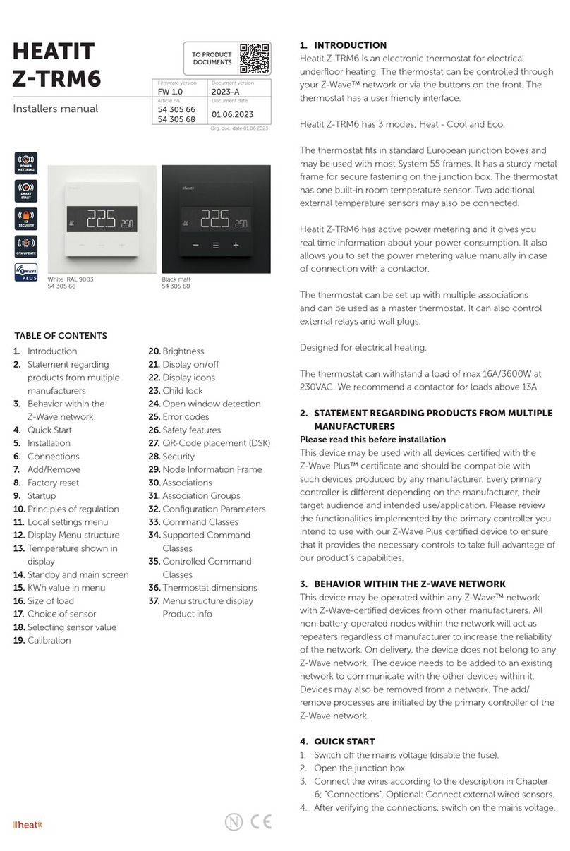
INTRODUCTION
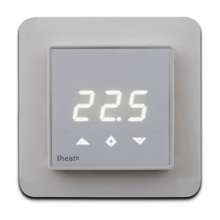
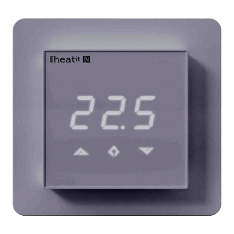
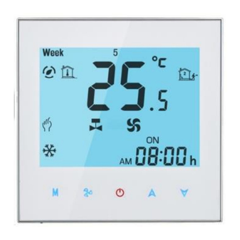
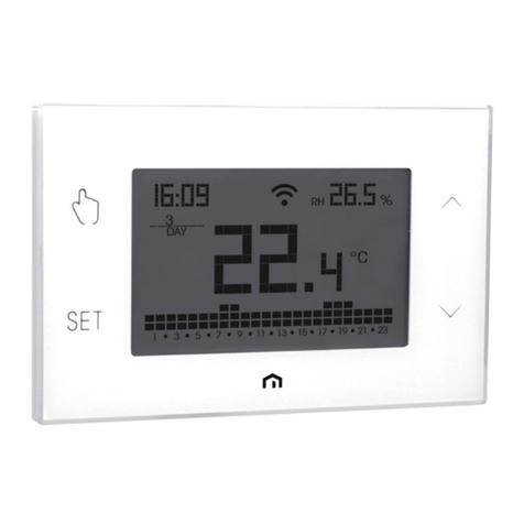
Heatit Z-TRM3 is an electronic thermostat for electrical
floor heating, designed to be mounted in a standard
flush box. The thermostat has a built-in Z-Wave chip
that can be connected with Home Automation
systems. Heatit Z-TRM3 is equipped with a single pole
switch and fits into System 55 frames. The thermostat
can withstand a load of max 16A /3600W at 230V.
The thermostat may be used for water based heating
if the thermostat is linked with the Heatit Z-Water.
NB! If the sensor mode is changed to A or AF mode
then a room sensor compensation process will
start, which limits maximum power output to 75%.
The thermostat adapts to the environment within
a few days. No internal sensor calibration should be
performed during the first few days.
INSTALLATION
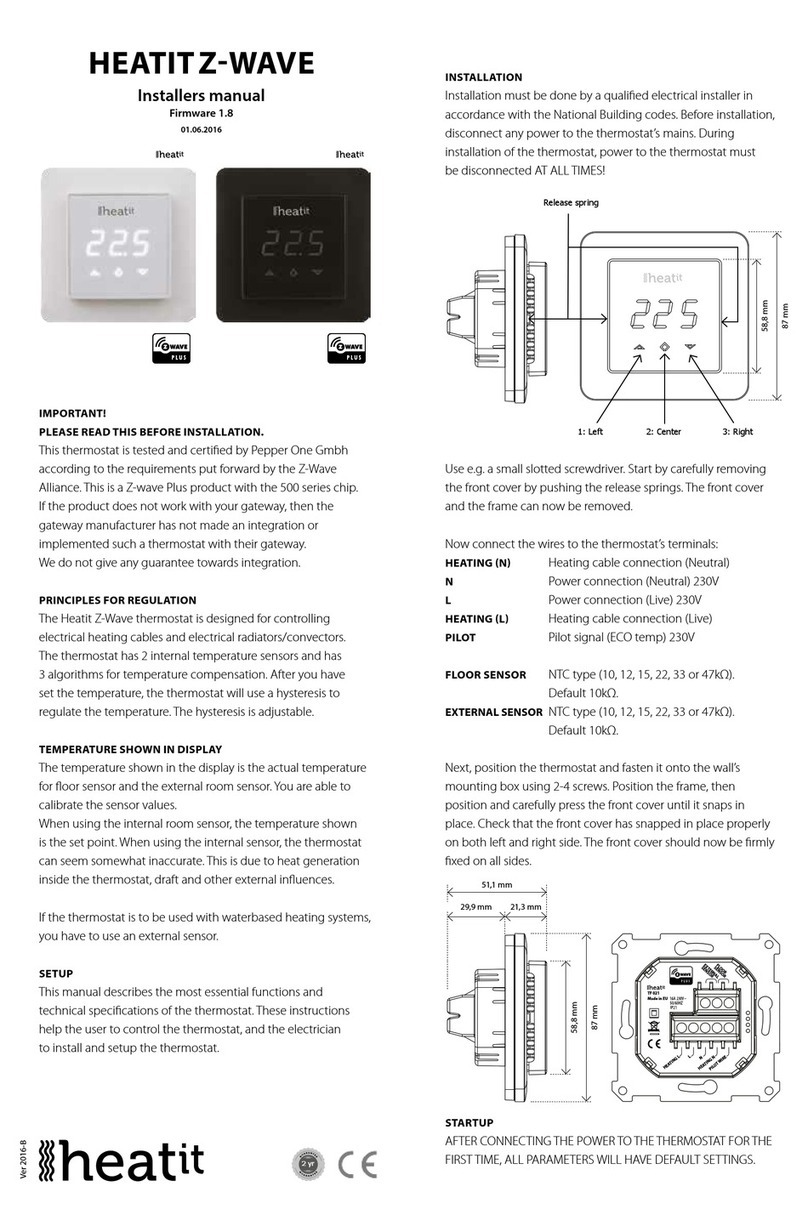
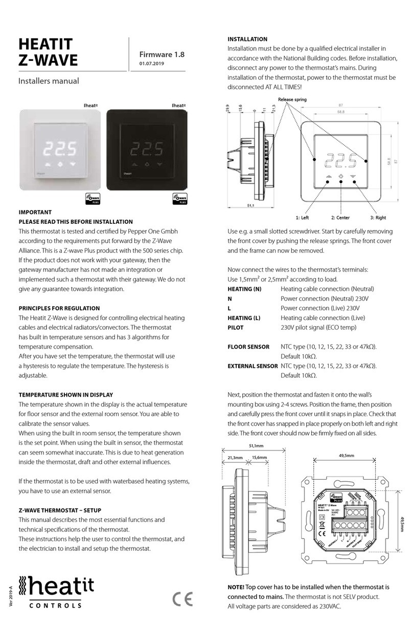
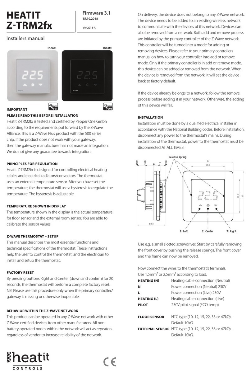
Use e.g. a small slotted screwdriver. Start by carefully
removing the front cover by pushing the release springs.
The front cover and the frame may now be removed.
Connect the wires to the thermostat terminals: Use
1,5mm² or 2,5mm² according to load.
HEATIT
ZTRM3
Quickguide Ver 2020-A
Read the full manual at:
manuals.heatit.com
manuals.thermo-oor.no
49,5mm
49,5mm
8
7
6
5
D
C
B
A
B
C
D
E
F
1
2
3
4
5
6
7
8
F
E
A
Date
Pages
Author
Designer
Scale
Document type
Document description
Item
Document code and revision
1/1
Modifier
Page size
-- A4
XL1331-A-02
XL1331
Drawing
PRINTED Z-TRM3
THERMOSTAT BOTTOM
21.01.2020
MM
--
This document and all information and data inclosed herein or herewith are the condential and proprietary property of Ouman Oy
and are not to be used, reproduced or disclosed in whole or in part to anyone without written permission of Ouman Oy.
Part: XKA367
Tool: YP1079
51,1mm
15,6mm
21,3mm
HEATING (N) Heating cable connection (Neutral)
N Power connection (Neutral) 230V
L Power connection (Live) 230V
HEATING (L) Heating cable connection
FLOOR SENSOR
NTC type (10, 12, 15, 22, 33 or 47kΩ). Default 10kΩ.
EXTERNAL SENSOR
NTC type (10, 12, 15, 22, 33 or 47kΩ). Default 10kΩ.
Next, position the thermostat and fasten it onto the
wall’s mounting box using 2-4 screws. Position the
frame, then position and carefully press the front cover
until it snaps in place. Check that the front cover has
snapped in place properly on both left and right side.
The front cover should now be firmly fixed on all sides.
To be able to to read the Power Metering, the load
needs to be connected to both heating L + N.
Release spring
58,8mm
87mm
1: Lef t 2: Center 3: Right
MULTIREG®Z- WAVE
