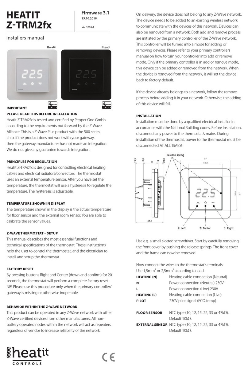
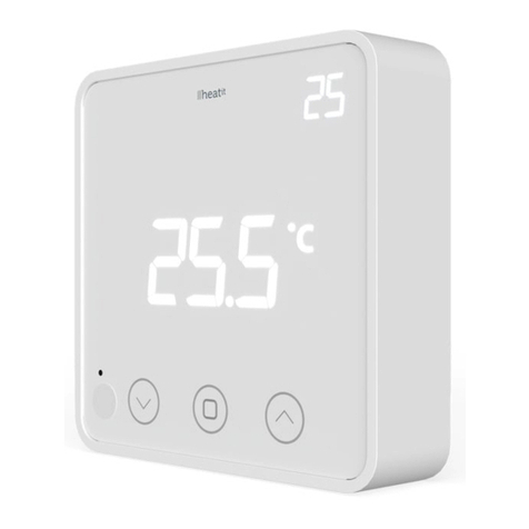
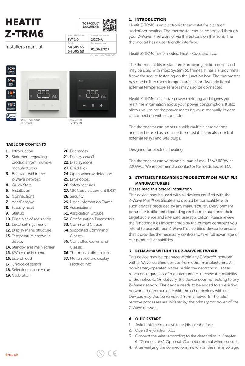
Heatit 7S NFC User guide

1. INTRODUCTION
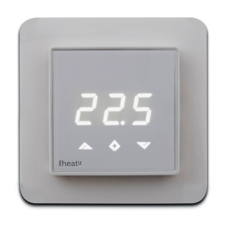
Heatit 7S NFC is an electronic thermostat for electrical underfloor
heating, designed to be mounted in a junction box. The thermostat
has three modes; Comfort, Economy and Automatic.
Heatit NFC Thermostat has a built-in NFC chip to control the
thermostat via a NFC app. All parameters can be configured from the
app, in addition you can set up weekly programs via the app.
Heatit 7S NFC Thermostat is equipped with a single-pole switch and
fits into System 55 frames. The thermostat can withstand a load of max
16A/3600W at 230VAC. We recommend a contactor for loads above
13A. The thermostat may be connected to two wired external sensors.
The thermostat is designed for electrical heating.
2. INSTALLATION
Installation must be done by a qualified electrician in accordance with
the national building codes. Before installation, disconnect any power
to the device from the mains. During installation of the device, power
to the device must be disconnected AT ALL TIMES!
Start carefully releasing the front cover by pushing the release springs.
Use e.g. a small slotted screwdriver. The front cover and frame may
now be removed.
TABLE OF CONTENTS
1. Introduction
2. Installation
3. Startup
4. Text on screen
4.1 Heating modes
4.2 Configuration menu
4.3 Other features accessible from the main screen
4.4 Error messages
5. User interface
6. Standby/Main screen
7. User modes
7.1 Heating modes
7.2 Operating modes
8. Smartphone application
8.1 Read configuration from thermostat
8.2 Main view
8.3 Weekly schedule
8.4 Advanced settings
8.5 Import/export temperature profile
8.6 Writing new configurations for the thermostat
8.7 Time
8.8 Text on thermostat display related to NFC data exchange
Product information
HEATIT 7S NFC
THERMOSTAT
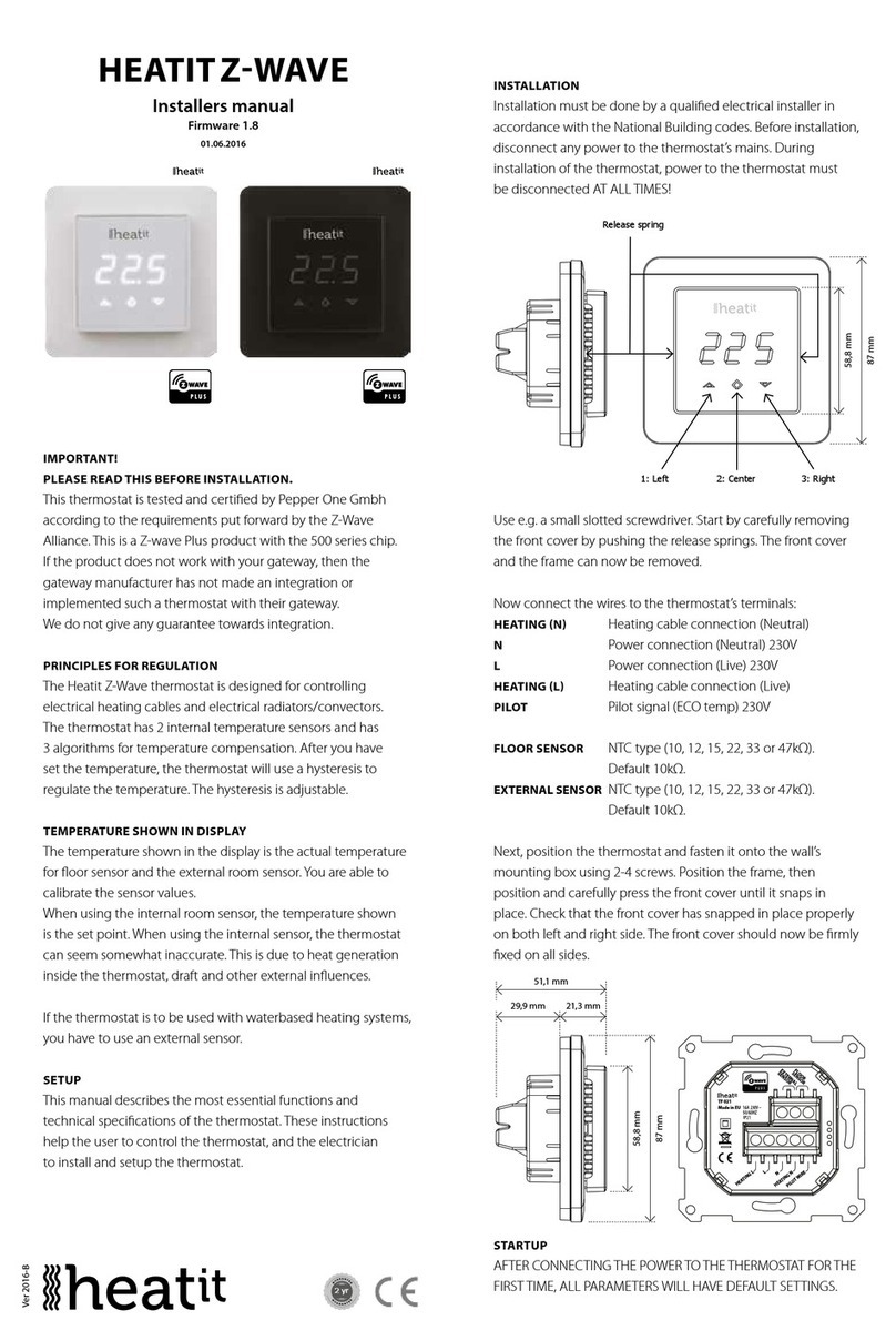
Installers manual
Ver 2022-A
Firmware 1.0
01.05.2022
Release springs
Art.no. 54 305 85

Connect the wires to the thermostat terminals. Use 1.5mm² or 2.5mm²
according to load.
Max tightening torque for terminal screws: 2Nm
PILOT Pilot Wire
HEATING (N) Heating cable connection (Neutral)
NPower connection (Neutral) 230VAC
LPower connection (Live) 230VAC
HEATING (L) Heating Cable connection (Live)
FLOOR SENSOR Floor temp sensor, NTC type
EXTERNAL SENSOR External temp sensor, NTC type
4. TEXT ON SCREEN
4.1 Heating modes
CO Comfort mode
ECO Economy mode
Aut Automatic mode
4.2 Conguration menu
OFF Thermostat will be turned off. Hold down middle button for
5 seconds to turn the thermostat on again.
OPE Operating mode (F, A, AF, A2)
FFloor sensor
AInternal sensor
AF Internal sensor + floor sensor
A2 External sensor
SEn Sensor menu. In this menu a correct NTC value of floor
sensor (in modes F, AF) or external sensor (in mode A2) can
be defined.
CAL Calibration menu. Displayed room temperature can be
adjusted to match the actual measured temperature.
Bri Contrast of display can be adjusted in this menu between
values 0...9 or A. In case of A, the brightness is regulated
automatically according to ambient light intensity.
ALo/AHI Room sensor low/high limit.
FLo/FHI Floor sensor low/high limit.
ESC Leave the menu and return to main screen.
4.3 Other features accessible from the main screen
don/dof Display on/off function. Press and hold left and middle
buttons for 5 secondss to change between don and dof.
rES Factory reset. Press and hold middle and right buttons for
20 seconds to reset the thermostat to factory default
settings.
LOC Child lock. Press and hold left and right button for 10
seconds to activate child lock. When child lock is activated
the thermostat ignores touch button inputs. Trying to make
changes causes LOC text to appear on screen. Child
lock can be deactivated by holding left and right button for
10 seconds.
4.4 Error messages
Er1 Internal error
Er3 Internal error
Er4 Floor sensor error. F or AF mode selected, sensor not connected or
damaged.
Er5 External sensor error. A2 mode selected, sensor not connected or
damaged.
5. USER INTERFACE
The thermostat is controlled by three capacitive touch buttons.These are:
• Left (Up)
• Middle (Conrm)
• Right (Down)
The red LED indicator on the right side of the user interface represents
the thermostat’s relay state. If the LED is on, the relay is closed, i.e. the
heating element is switched on. If the LED is off, the relay is open.
49,5mm
49,5mm
51,1mm
15,6mm 21,3mm
86mm
Use an extra screw connector to connect heating cable earth wire to
mains earth wire. Next, position the thermostat and fasten it into the
wall’s junction box using 2-4 screws. Position the frame, then position
and carefully press the front cover until it snaps in place. Check that the
front cover is placed properly on sides. The front cover should now fit
firmly fixed on all sides.
Note! The top cover has to be installed when the thermostat
is connected to the main power source. The thermostat is not
a SELV product. All voltage parts must be considered to be
230VAC.
3. STARTUP
After connecting the power to the thermostat for the first time, all
parameters will have default settings. (Alternative settings are shown in
parenthesis).
Heating mode CO (ECO, Aut)
Operating mode FFloor sensor
AInternal sensor
AF Internal sensor + floor sensor
A2 External sensor
Floor sensor type Default value 10kΩ (6.8, 10, 12, 15, 22, 33, 47kΩ)
Calibration 0°C (-4°C…4°C)
Display contrast 3 (0…9, A)
Temperature limits: FLo (Floor min temp.)
FHI (Floor max temp.)
ALo (Room min temp.)
AHI (Room max temp.)
Note: Wooden floors require a floor sensor to be connected. Most
manufacturers of wooden floors state that the maximum temperature
must be limited to 27°C.

6. STANDBY/MAIN SCREEN
If the thermostat remains untouched for a while, it will automatically
go to standby screen. In case dof is activated, the standby screen will
be totally black and in case don is activated, room temperature will be
on the screen at low brightness.
The thermostat displays the main screen if any of the buttons are
pressed. On the main screen it is possible to change the setpoint of
CO or ECO mode by pressing left or right buttons (screen blinks during
selection). If the left or right button is pressed in automatic (Aut) mode,
the display shows current active setpoint according to schedule.
Heating mode can be toggled between CO, ECO and Aut by holding
the middle button for 1 second.
The configuration menu is accessed by holding the middle button for
5 seconds. The left and right button allows you to navigate between
configuration menu items, and a short push on middle button enters
the selected menu. Configuration parameters can be changed by
left and right button. A 1 second push on middle button confirms
parameter selection, after that “Sto” is displayed.
7. USER MODES
7.1 Heating modes
The thermostat has 3 different heating modes:
Comfort (CO), Economy (ECO) and Automatic (Aut).
Comfort mode: Comfort mode is used as“at home”mode with
warm and comfortable setpoint (by default
21°C)
Economy mode: Economy mode is used as“away”mode with
lower, energy-saving setpoint (by default 18°C).
Automatic mode: Automatic mode helps to save energy by
changing the setpoint according to weekly
schedule (see“Weekly Schedule” in chapter 8).
The schedule can be configured from
smartphone application only. By default,
the weekly schedule is configured to constant
21°C setpoint.
Pilot Wire
CO and ECO modes can also be toggled by pilot wire input. In case
a full-period line voltage is applied to the pilot wire, the thermostat
switches to ECO mode. If the line voltage is switched off from pilot
input, the thermostat enters CO mode. Pilot wire input has no effect in
automatic mode.
7.2 Operating modes
Operating mode A
In operating mode A, the thermostat regulates room temperature
according to the built-in room temperature sensor. Parameters AHI and
ALo limit setpoint selection range (FHI/FLo are not used).
Operating mode F
In operating mode F, the thermostat regulates floor temperature
according to the floor sensor (a floor sensor must be connected).
Minimum and maximum floor temperature values can be defined with
FHI and FLo parameters (AHI/ALo are not used).
Operating mode AF
In operating mode AF the thermostat regulates room temperature
according to the built-in room temperature sensor while ensuring that
the floor temperature is within the limits of FHI and FLo settings (a floor
sensor must be connected). This operating mode is practical for use
with wooden floors, where floor temperature should not exceed 27°C.
Parameters AHI and ALo limit setpoint selection range in mode AF, as
in mode A.
Operating mode A2
In operating mode A2 the thermostat regulates temperature according
to an external sensor temperature. Limits AHI/ALo and FHI/FLo are not
used.
8. SMARTPHONE APPLICATION
The smartphone application allows you to control the thermostat by
NFC (Near Field Communication). All the parameters of the thermostat
can be configured through the app. In addition, the app allows you to
create weekly schedules in automatic mode.
8.1 Read conguration from thermostat
Each time the app is started, a “read”view is displayed, prompting you
to place your phone near the thermostat. Move your phone close to
the thermostat front panel (0…3 cm) and wait until the app displays
a success (or failure) message. With a successful read operation, the
main view is displayed and the phone may be moved away from the
thermostat.
If necessary, the settings can be reread from the
thermostat by tapping the orange “Read”button in
the top right corner of the screen.
8.2 Main view
In the main view you may select the desired heating mode (Off, Eco,
Comfort, Automatic) and change setpoint values.
Download and install
the app from the link in
the QR-code:
For iOS For Android
Download and install
the app from the link in
the QR-code:
Main view (Comfort mode selected)

8.3 Weekly schedule
When automatic mode is selected, a weekly schedule may be
configured. A schedule of each weekday may be viewed and modified
by tapping on circular weekday buttons. You may add up to three time
periods with different setpoints and durations per day by tapping“Add
time period”. The base temperature value defines the setpoint between
these periods.
The weekday button changes color tone if the schedule of the day is
different compared to other days. Days with same schedule settings
have the same color tone.
In order to copy one weekday schedule to the next, tap“Copy to” and
select the weekdays where you want to paste the schedule of the
currently selected day.
Weekly schedules may be reset by tapping“Delete schedule” in the
bottom left corner of the main view.
8.4 Advanced settings
Advanced settings that are present in the configuration menu of the
thermostat (operating mode, sensor type, etc.) can be changed from
the side menu in the app, under“Advanced settings. ”The side menu
is accessed by tapping the“burger”icon in top left corner of the main
view.
One additional parameter under advanced settings is configurable
only from the app - namely“Adaptive start”. If adaptive start is enabled,
heating in automatic mode is turned on in advance before each
positive setpoint change (i.e., when changing from a low temperature
to a higher temperature). The temperature setpoint configured in the
schedule is reached approximately at the specified time. If adaptive
start is turned off, the thermostat simply changes the setpoint
according to schedule, and heating is not turned on in advance.
Main view (Automatic mode selected)
8.5 Import/export temperature prole
It is possible to export (save) or import (load) your temperature profile
in the phone memory. The temperature profile includes all the data in
the main view: heating mode (Off, CO, ECO, Aut), CO and ECO setpoints
and weekly schedule data. Advanced settings in the side menu are not
stored under temperature profile to avoid false configuration if more
than one thermostat is configured from the same smartphone.
8.6 Writing new congurations for the thermostat
To write new configurations for the thermostat, tap “Send”button in
the bottom right corner of the screen.
When the“Write”screen appears, hold the phone
close to thermostat front panel and wait until
success or failure message is displayed (do not
remove the phone from thermostat before this
message appears).
8.7 Time
During every NFC write operation the clock inside the thermostat is
automatically synchronized to allow correct operation of automatic
mode. In case of power failure the clock remains operational for 24
to 48 hours. Please note that the thermostat does not automatically
adjust to/from daylight saving time.
8.8 Text on thermostat display related to NFC data exchange
During read or write operation the display shows“nFC”, indicating that
the NFC field is active. After a successful write operation the thermostat
displays the text“Sto”.
Side menu

Heatit Controls AB l Läkarvägen 4, 454 31 BRASTAD, SWEDEN
Heatit Controls AB can not be held liable for typographical errors, other errors or omittances in our information.
Product specifications may change without further notice. All electrical installations must be carried out by a licensed
electrician. The product must be installed in accordance with national building codes and our installers manual.
DISPOSAL GUIDELINES
Do not dispose of electrical appliances as unsorted municipal waste, use separate collection
facilities. Contact your local government for information regarding the collection systems
available. If electrical appliances are disposed of in landfills or dumps, hazardous substances
can leak into the groundwater and get into the food chain, damaging health and well-being.
ART. NO. PRODUCT COLOR
54 305 85 Heatit 7S NFC Thermostat White RAL 9003
PRODUCT INFO Heatit 7S NFC
FEATURES
• NFC thermostat
• LED-display, 7 segment
• Floor sensor
• Internal room sensor
• External sensor (not included)
• Adaptive regulation
• 3 modes: Comfort, Economy and Automatic
• Weekly schedule
• Setback temperature through pilot wire
• Child lock
• Calibration for internal sensor
• Smartphone requirements: Iphone 7, Android 6.0 or later +
NFC support
• English/Swedish/Suomi language options
TECHNICAL DATA
Protocol NFC
Rated voltage 230VAC 50Hz
Max load 3600W (resistive loads only)
Use contactor for loads higher than 13A
Max current 16A
Power consumption 0.5W
Ambient temperature 5°C to 40°C (during operation)
Temperature range 5°C to 40°C
Hysteresis 0.5°C
Compatible with NTC
sensors with values 6.8, 10, 12, 15, 22, 33 og 47kΩ @ 25°C
IP Code IP 21
Approvals CE
Approved for use in bathrooms.
TERMINAL
Use 1.5mm² or 2.5mm² according to load.
MAINTENANCE
The device is maintenance-free, but must never be covered.
This manual suits for next models
1
Table of contents
Other Heatit Thermostat manuals

Heatit
Heatit Z-WAVE User guide

Heatit
Heatit HEATITZ-WAVE User guide

Heatit
Heatit Z-TRM6 User guide

Heatit
Heatit ZM 16A User guide

Heatit
Heatit Z-Temp2 User guide

Heatit
Heatit ET-7AW User manual

Heatit
Heatit Z-TRM3 User guide

Heatit
Heatit Z-TRM2 User guide

Heatit
Heatit Z-TEMP2 User guide

Heatit
Heatit Z-TEMP2 User manual
Popular Thermostat manuals by other brands

Lauda
Lauda PTT operating instructions

OJ Electronics
OJ Electronics Microline OTN-1991H11 instructions

Lux Products
Lux Products T40-1143 Installation and operating instructions

Hunter
Hunter F42213 owner's manual

Honeywell
Honeywell TB6980 Installation and user guide

Technotherm
Technotherm TPF-Eco Control guide