Heatit ZM 16A User guide
1. INTRODUCTION
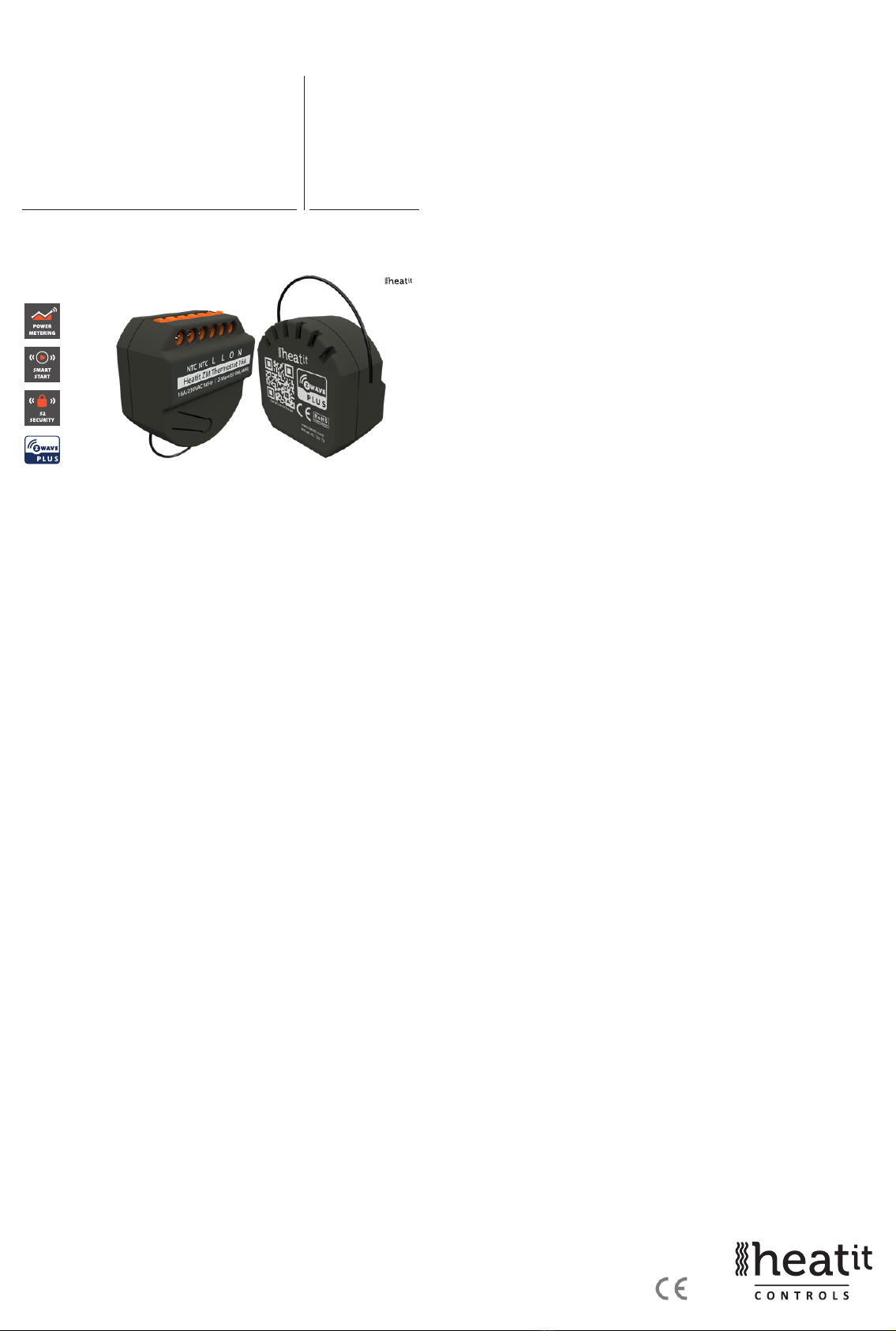
Heatit ZM Thermostat 16A is an electronic thermostat for electrical
oor heating designed for in-wall installations.
The thermostat allows you to control your electrical heating through
your Z-Wave™ network. The module is equipped with a 16A single pole
relay. The thermostat requires you to connect an external wired sensor
which is included with the device.
The device can withstand a max load of 16A at 230VAC.
2. STATEMENT REGARDING PRODUCTS FROM MULTIPLE
MANUFACTURERS
Please read this before installation
This device may be used with all devices certied with the Z-Wave
Plus™ certicate and should be compatible with such devices
produced by any manufacturer. Every primary controller is dierent
depending on the manufacturer, their target audience and intended
use/application. Please review the functionalities implemented by the
primary controller you intend to use with our Z-Wave Plus certied
device to ensure that it provides the necessary controls to take full
advantage of our product’s capabilities.
3. BEHAVIOR WITHIN THE ZWAVE™ NETWORK
This device may be operated within any Z-Wave network with
Z-Wave-certied devices from other manufacturers. All non-battery-
operated nodes within the network will act as repeaters regardless of
manufacturer to increase the reliability of the network. On delivery, the
device does not belong to any Z-Wave network.
The device needs to be added to an existing network to communicate
with the other devices within it. Devices may also be removed from
a network. The add/remove processes are initiated by the primary
controller of the Z-Wave network.
4. QUICK START
1. Switch o the mains supply (disable the fuse).
2. Open the wall box.
3. Connect the wires according to the description in Chapter 5;
”Installation”.
4. After verifying the connections, switch the mains supply back on.
5. Set the primary controller in add mode (security/non-security).
6. Press the conguration button 3 times in rapid succession.
7. The device LED will blink in green when the adding procedure has
been successfully initiated. When the device is included in the home
automation system, the LED will light up in green for 3 seconds.
5. INSTALLATION
Installation must be done by a qualied electrician in accordance with
the national building codes. Before installation, disconnect any power
to the device mains. During installation of the device, power to the
device must be disconnected AT ALL TIMES!
The product allows for wiring of cables with a cross section of up to
1x2.5mm2.
TABLE OF CONTENTS
1. Introduction
2. Statement regarding products from multiple manufacturers
3. Behavior within the Z-Wave™ network
4. Quick Start
5. Installation
6. Add/Remove
6.1 Method 1: Standard (Manual)
6.2 Method 2: SmartStart (Automatic)
7. Factory Reset
8. Startup
9. Principles of regulation
10. Hysteresis
11. Safety Features
11.1 Overload
11.2 Overheating
12. Calibration
13. LED Blinking patterns description
14. QR-Code placement (DSK)
15. Security
16. Node Information Frame
17. Associations
17.1 Setting and removing associations
17.2 Associations Groups
18. Conguration Parameters
19. Command Classes
19.1 Basic Command Class
19.2 Binary Switch Command Class
19.3 Meter Command Class
19.4 Indicator Command Class
20. Supported Command Classes
Product Information
HEATIT ZM
THERMOSTAT
16A Ver 2021-A
Firmware 1.0
01.09.2021
Installers manual

NPower connection (Neutral) 230VAC.
OOutput. Load need to be connected between O and Neutral.
LPower connection (Live) 230VAC.
LPower connection (Live) 230VAC.
NTC 10K NTC Temperature sensor.
NTC 10K NTC Temperature sensor.
6. ADD/REMOVE
Please read this before installation
The primary controller/gateway has a mode for adding or removing
devices. Please refer to your primary controller manual on how to set
the primary controller in add/remove mode. The device may only be
added or removed from the network if the primary controller is in add/
remove mode.
When the device is removed from the network, it will NOT revert to
factory settings.
There are two ways to add the device to a Z-Wave network.
6.1 Method 1: Standard (Manual)
Add/remove mode is indicated on the device by a blinking green
LED. It indicated this for 90 seconds until a timeout occurs, or until the
module has been added to/removed from the network.
To start the conguration process, press the conguration button 3
times in rapid succession. The LED will light up green for 3 seconds if
adding/removing is successful.
The device is now ready for use with default settings.
NB! When the device is removed from the gateway, the parameters are
not reset. To reset the parameters, see Chapter 7 ”Factory reset”.
If inclusion fails, please perform a ”remove device” process and try
again. If inclusion fails again, please see Chapter 7 “Factory reset”.
6.2 Method 2: SmartStart (Automatic)
SmartStart enabled products may be added to a Z-Wave network
by scanning the Z-Wave QR-Code on the product if your primary
controller supports SmartStart inclusion. No further action is required
and the SmartStart product will be added automatically after being
powered on within range of the primary controller.
7. FACTORY RESET
Press and hold the conguration button. After 3 seconds the LED will start to
blink in green. After 20 seconds the LED will start to blink green rapidly for 5
seconds. You may now release the button.
NB! Please use this procedure only when the primary controller/
gateway is missing or otherwise inoperable.
8. STARTUP
After powering up the device for the rst time, all the parameters will have
default settings.
9. PRINCIPLES OF REGULATION
The thermostat uses temperature readings retrieved from the sensor to
regulate heating. When you have chosen a setpoint temperature, the
thermostat will use an internal hysteresis to regulate the temperature.
10. HYSTERESIS
You can make changes to the thermostat hysteresis. You may change
the hysteresis from between 0.3°C and 3.0°C using parameter 2.
The default setting is 0.5°C. When using water-based heating, the
recommended hysteresis is 1.0°C.
11. SAFETY FEATURES
The device security features make the device safe to use and noties the user
of any unexpected behavior in the device, such as overload or overheating.
If this happens, the thermostat turns the relay OFF and starts to blink red
and green from the LED until the error(s) have been resolved and the device
has been disconnected and reconnected from the mains.The following
temperature notications will be sent to the gateway/controller:
• 121°C = Overheat
• 122°C = Overload
• 123°C = Sensor short
• 124°C = Sensor not connected
11.1 Overload
The device features a 16A overload protection. The overload is triggered if
there is a current draw of more than 16A. The relay allows for inrush current. If
the current is between 16-20A it waits for 2 seconds, if it is between 20-30A it
waits for 0.5 seconds and if it is above 30A it will wait for 0.2 seconds. After the
given time the device will do the following:
• Set the relay OFF
• Blink red and green
• Send a temperature report of 122°C
To clear the overload state, the connected load has to be checked and the
thermostat must be disconnected and reconnected from the mains.
11.2 Overheating
The device features an internal temperature sensor which prevents
overheating inside the device or wall.
When overheating is detected, the device will:
• Set the relay to OFF
• Blink red and green
• Send a temperature report of 121°C
To clear the overheating state, the thermostat must be allowed to cool
down and the cause of the overheating must be removed.
11.3 Sensor short circuit
The device has the ability to detect a sensor short circuit. This is to
ensure that the device regulates correctly from the sensor.
When a sensor short circuit is detected, the device will:
• Set the relay to OFF
• Blink red and green
• Send a temperature report of 123°C
To clear the sensor short circuit error the device has to be
disconnected from the mains, then the wiring and sensor needs to be
checked. When the fault is resolved the mains can be reconnected and
the device will function normally again.
NOLL
NTC
NTC
NTC
Last
Load
L N Conguration button
LED light in back

11.4 Sensor not connected
The device has the ability to detect when there is no sensor connected
or when the sensor is broken and causes an open circuit.
When the device detects the sensor error, the device will:
• Set the relay to OFF
• Blink red and green from the LED
• Send a temperature report of 124°C
To clear the “Sensor not connected” error the device has to be
disconnected from the mains, and the wiring and sensor needs to be
checked. When the fault is resolved the mains can be reconnected and
the device will function normally again.
12. CALIBRATION
Parameter 6 allows you to calibrate the temperature displayed in the
controller/gateway and what the thermostat uses for regulation. If
the temperature sensor readout is not correct, you can make minor
changes to the temperature readout. You can calibrate the measured
temperature by ±6°C degrees.
13. LED BLINKING PATTERNS DESCRIPTION
The device supports numerous LED blinking patterns to make it as
easy as possible to identify what the device is doing.
Error code
Error status on device:
Alternating red and green blinking
pattern (100ms duration) for 5
seconds.
200ms
0s 1s 2s 3s 4s 5s
400ms 800ms 1000ms
600ms 900ms
Device Not in Network
The LED will ash red when the de-
vice is not added to a Z-Wave network
0s 1s 2s 3s 4s 5s
Device Status
On: Green
O: Red
When the device is in OFF Mode, LEDs
will be o.
Add/Remove
When device enters add/remove
mode the LED will ash green.
If successful, the LED will light up in
green for 3 seconds.
If unsuccessful, the LED will light up in
red for 3 seconds.
0s 1s 2s 3s xs x+3s
Success
Fail
14. QRCODE PLACEMENT DSK
The QR-Code is needed when including a device using S2 security or
SmartStart. The DSK can be found in the QR-Code and is located;
• On the product.
• On the Quick Guide manual.
• On the product box.
15. SECURITY
S2 security enhances Z-Wave Plus with an additional layer of AES
128-bit encryption of the wireless Z-Wave communication to prevent
hacking and man-in-middle attacks on the home network. This device
supports S2 and has a Z-Wave DSK QR-Code label that may be used
when the module is added to the Z-Wave home network. The primary
controller will ask for a 5-digit code, which can be found underneath
0s 1s 2s 3s 4s 5s
0s 1s 2s 3s 4s 5s
the QR-Code. The primary controller will then ask you to conrm the
rest of the code that is contained in the QR-Code.
16. NODE INFORMATION FRAME
The node information frame is the ”business card”of a Z-Wave device.
It contains information about the device type and its technical features.
The add and remove procedure of the device is conrmed by sending
out a node information frame. Besides this, it may be necessary for
certain network operations to send out a node information frame.
17. ASSOCIATIONS
Z-Wave devices interact with other Z-Wave devices. The relationship
between one device controlling another device is called an association.
In order to control a subordinate device, the controlling device needs
to maintain a list of devices that will receive controlling commands.
These lists are called ”Association Groups”. They are always related to
the specic event triggered (e.g., sensor reports). In case the event is
triggered, all devices stored in the respective association group will
receive a joint wireless command.
17.1 Setting and removing associations
Associations may be assigned and removed via Z-Wave commands.
Please refer to your primary controller/Z-Wave gateway for more
information.
17.2 Association groups
RELAY DEVICE THE MAIN DEVICE
Group 1
Lifeline
Lifeline. (Normally used by the Z-Wave Controller) Sends:
- Device Reset Notications.
- Thermostat Setpoint Reports.
- Thermostat Mode Reports.
- Thermostat Operating State.
- Sensor Multilevel Report.
- Meter report.
- Basic report.
- Indicator report.
Max. nodes in group: 5
Group 2
External Control
Send Binary Switch set commands representing the
status of the internal relay.
(0x00, 0xFF) ON/OFF
Max. nodes in group: 5
18. CONFIGURATION PARAMETERS
Z-Wave products are supposed to work out of the box after inclusion.
Some device conguration may, however, alter the functionality to
better serve user needs or unlock further enhanced features. All the
parameters below do not feature altering capabilities, advanced or
read only ag.
Parameter 1, Parameter size 1. Operating mode.
Sets the thermostat mode.
NO
#
PARA
SIZE
(BYTE) NAME
SHORT
DESCRIPTION /
COMMENT
MIN MAX
DE-
FAU LT
DESCRIPTION
OFVALUE
1 1 Operating
mode
Sets the thermo-
stat mode
0 1 OFF
Thermostat will
not operate
1Heating Thermo-
stat is in heating
mode
2 Cooling
Thermostat is in
cooling mode

PRECISCION (VALUE) SCALE SUPPORTED (VALUE) SIZE
2 decimals (0x02) kWh (0x01) 4
2 decimals (0x02) W (0x02) 4
19.4 Indicator Command Class
The device supports the Indicator Command Class.
The indicator Command Class will turn ON/OFF internal LED as wanted
as well as turning the relay ON/OFF.
Controlled command classes
INSECURE INCLUSION
INSECURE ON
SECURE INCLUSION
SECURE ON
SECURE INCLUSION
Binary Switch v2 Yes Yes
20. SUPPORTED COMMAND CLASSES
The following table lists all Command Classes supported by the Z-Wave
device. The device supports S0, S2 Authenticated security and S2
Unauthenticated security.
INSECURE INCLUSION
INSECURE ON
SECURE INCLUSION
SECURE ON
SECURE INCLUSION
Association v2 Yes Yes
Association Group
Information v3
Yes Yes
Basic v2 Yes Yes
Conguration v4 Yes Yes
Device Reset
Locally v1
Yes Yes
Firmware Update
Meta Data v5
Yes Yes
Manufacturer
Specic v2
Yes Yes
Meter v3 Yes Yes
Multichannel
Association v3
Yes Yes
Power level v1 Yes Yes
Security 0 v1 Yes Yes
Security 2 v1 Yes Yes
Supervision v1 Yes Yes
Indicator v3 Yes Yes
Transport Service
v2
Yes Yes
Version v3 Yes Yes
Z-Wave Plus Infor-
mation v2
Yes Yes
Thermostat Set-
point v3
Yes Yes
Thermostat Mode
v3
Yes Yes
Thermostat Operat-
ing State v1
Yes Yes
Multilevel Sensor v5 Yes Yes
2 1 Tem-
perature
control
hysteresis
Chooses the
hysteresis for the
thermostat.
3 30 5
(0.5°C)
0.3°C to 3.0°C.
3 2 Minimum
tempera-
ture
Decides the
lowest setpoint
temperature
allowed by the
thermostat.
50 400 50
(5°C)
5.0°C to 40.0°C.
4 2 Maximum
tempera-
ture
Decides the
highest setpoint
temperature
allowed by the
thermostat.
50 400 400
(40°C)
5.0°C to 40.0°C.
5 2 Ther-
mostat
setpoint
Decides the ther-
mostat setpoint.
50 400 210
(21°C)
5.0°C to 40.0°C.
6 1 Sensor
calibration
Manually
calibrates the
sensor by ±6°C.
-60 60 0 -6.0°C to 6.0°C.
Calibrates the
sensor by ±6°C.
NB! To set a
negative value,
use 256 and
subtract the
desired value.
7 2 Tempera-
ture report
interval
Sets time interval
between
consecutive
temperature
reports.
30 65535 1020
(17
min-
utes)
30 to 65 535
seconds.
8 1 Tempera-
ture report
hysteresis
Temperature
reports based
on change in
temperature from
last report.
0 10
(1°C)
Temperature
report based on
delta value is
disabled.
1 100 0.1°C to 10°C.
9 2 Meter
report
interval
Sets time interval
between consecu-
tive meter reports.
30 65535 1020
(17
min-
utes)
30 to 65 535
seconds.
10 1 Inverted
output
Decides if the relay
output should be
inverted.
0 0 Standard input.
1 Inverted input.
11 2 Relay state
update
interval
Sets the time
interval of how
often the device
reports Binary
Switch Set and
thermostat mode.
0 43200
(12
hours)
Disabled
30 65535 30 to 65535
seconds.
19. COMMAND CLASSES
Besides the mandatory command classes, the device has support for
the following command classes:
19.1 Basic Command Class
A Basic command to the device will change the thermostat mode.
Uses the following values:
0x00 = OFF (0x00)
0xFF = HEAT (0x01)
19.2 Binary Switch Command Class
Binary Switch commands are used to control external relays associated
in group 2.
Uses the following values:
0x00 = OFF
0xFF = ON
19.3 Meter Command Class
The device supports Meter Command Class Get, and the thermostat
will only respond on supported electric meter scales:
kWh (accumulated) and Watt (instant). The device will report when
asked:
Rate import: Import (0x01)
Meter type: Electric meter (0x01)
Precision: 2 decimals (0x02)
Heatit Controls AB l Läkarvägen 4, 454 31 BRASTAD, SWEDEN
Heatit Controls AB can not be held liable for typographical errors, other errors or omittances in our information.
Product specifications may change without further notice. All electrical installations must be carried out by a licensed
electrician. The product must be installed in accordance with national building codes and our installers manual.
DISPOSAL GUIDELINES
Do not dispose of electrical appliances as unsorted municipal waste, use separate collection
facilities. Contact your local government for information regarding the collection systems
available. If electrical appliances are disposed of in landlls or dumps, hazardous substances
can leak into the groundwater and get into the food chain, damaging health and well-being.
ART. NO. PRODUCT COLOR FREQUENCY
45 126 73 Heatit ZM Thermostat 16A Grey RAL 6015 EU 868.4MHz
PRODUCT INFO Heatit ZM Thermostat 16A
FEATURES
• Z-Wave thermostat for in-wall installations
• 16A/3600W
• NTC 10 sensor
• SmartStart
• Firmware update (OTA)
• Power Metering
• Supports encryption modes S0, S2 Authenticated Class,
S2 Unauthenticated Class
This product is a security-enabled Z-Wave Plus product with
encryption. The product must be used with a security-enabled
Z-Wave Controller in order to fully utilize the product.
TECHNICAL DATA
Protocol Z-Wave
Chip Z-Wave 700 chip
Rated voltage 230VAC 50Hz
Max load 3600W 16A
Power Consumption <1W
Ambient temperature 5°C to 40°C (-30°C to 70°C storage)
Humidity Max 95% RH
Range RF Min. 40 meters
IP Code IP 20
Size (DxWxH) 46 x 45 x 25mm
Approvals Z-Wave Plus V2, CE
EN 60669-1:2018, EN 60669-2-1:2004 + A1:2009, EN 60669-1:2004/
A12:2010, EN 60669-2-5:2016, IEC 965-2-1, EN 62479:2010,
ETSI EN 301 489-3 V2.1.1(2017-03), ETSIEN300 220-2 V3.1.1
(2017-02), RoHS 2002/95/EG, WEE 2002/96/EC
MAINTENANCE
The device is maintenance-free. Indoor use only.
The product is also available in other Z-Wave frequency versions on request.
This manual suits for next models
1
Table of contents
Other Heatit Thermostat manuals

Heatit
Heatit Z-TEMP2 User manual

Heatit
Heatit Z-TRM2fx User guide

Heatit
Heatit Z-TEMP2 User manual

Heatit
Heatit Z-TRM2 User guide

Heatit
Heatit Z-TEMP2 User guide

Heatit
Heatit HEATITZ-WAVE User guide

Heatit
Heatit Z-TRM3 User manual

Heatit
Heatit Z-WAVE User guide

Heatit
Heatit 7S NFC User guide

Heatit
Heatit Z-TRM6 User guide


Popular Thermostat manuals by other brands


Aube Technologies
Aube Technologies EConnect Wireless Thermostat Kit TA7210 System installation guide

koban
koban KTD 01 manual

Purmo
Purmo Unisenza Installation and user manual

Tekmar
Tekmar tekmarNet 2 530 Installation & operation manual

Carrier
Carrier 53DFST2-NP installation instructions

Hunter
Hunter 40080 quick guide


