SICK MPB10 User manual

OPERATING INSTRUCTIONS
MPB10
Multi Physics Box

Described product
MPB10
Manufacturer
SICK AG
Erwin-Sick-Str. 1
79183 Waldkirch
Germany
Legal information
This work is protected by copyright. Any rights derived from the copyright shall be
reserved for SICK AG. Reproduction of this document or parts of this document is
only permissible within the limits of the legal determination of Copyright Law. Any modi‐
fication, abridgment or translation of this document is prohibited without the express
written permission of SICK AG.
The trademarks stated in this document are the property of their respective owner.
© SICK AG. All rights reserved.
Original document
This document is an original document of SICK AG.
2006/42/EC
NO
SAFETY
2O P E R A T I N G I N S T R U C T I O N S | MPB10 8028041/2022-08-16 | SICK
Subject to change without notice

Contents
1 Information on the operating instructions..................................... 5
2 About this document........................................................................ 6
2.1 Further information................................................................................... 6
2.2 Symbols and document conventions...................................................... 6
2.3 Customer service...................................................................................... 6
3 Safety information............................................................................ 8
3.1 Intended use............................................................................................. 8
3.2 Improper use............................................................................................. 8
3.3 Limitation of liability................................................................................. 8
3.4 Requirements for skilled persons and operating personnel.................. 9
3.5 Hazard warnings and operational safety................................................. 9
4 Product description........................................................................... 10
4.1 Product ID.................................................................................................. 10
4.1.1 Device view............................................................................... 10
4.2 Product characteristics............................................................................ 10
4.2.1 Product features...................................................................... 10
4.2.2 Status indicators...................................................................... 11
4.2.3 System architecture................................................................. 11
4.3 Vibration analysis (Index 4474-4588).................................................... 12
4.3.1 Principle of operation.............................................................. 12
4.3.2 Settings for vibration analysis (Index 4477, 4479, 4482,
4531)........................................................................................ 12
4.3.3 Trigger (Index 4474-4475)...................................................... 15
4.3.4 Activity detection (Index 4479-4480).................................... 16
4.3.5 Vibration in time range (Index 4483-4539)........................... 16
4.3.6 Vibration in the frequency range............................................ 18
4.4 Temperature monitoring (Index 4352-4355).......................................... 19
4.5 Shock (Index 4434–4448)...................................................................... 19
5 Transport and storage....................................................................... 20
5.1 Transport................................................................................................... 20
5.2 Transport inspection................................................................................. 20
5.3 Storage...................................................................................................... 20
6 Mounting............................................................................................. 21
6.1 Mounting requirements............................................................................ 21
6.2 Mounting................................................................................................... 21
6.3 Mounting methods................................................................................... 21
6.4 Optional accessories................................................................................ 23
7 Electrical installation........................................................................ 24
7.1 Safety......................................................................................................... 24
CONTENTS
8028041/2022-08-16 | SICK O P E R A T I N G I N S T R U C T I O N S | MPB10 3
Subject to change without notice
7.1.1 Notes on the electrical installation......................................... 24
7.1.2 Wiring instructions................................................................... 24
7.2 Connections.............................................................................................. 26
7.2.1 Pin assignment/Connection diagram + wire colors.............. 26
7.3 Connecting the supply voltage................................................................. 26
8 Commissioning.................................................................................. 27
8.1 Overview of commissioning steps........................................................... 27
8.2 Put the sensor into operation for the first time...................................... 27
9 Operation............................................................................................ 28
9.1 General notes on operation..................................................................... 28
9.2 Alarm behavior (Index 4842)................................................................... 28
9.3 Vibration monitoring................................................................................. 31
9.3.1 Monitoring in time range......................................................... 31
9.3.2 Monitoring in frequency range (Index 4549-4582)............... 35
9.3.3 Readout of raw data................................................................ 40
9.4 Temperature monitoring (Index 4352-4355).......................................... 43
9.5 Shock detection (Index 4434-4448)....................................................... 43
9.6 Configuration of digital outputs............................................................... 44
9.7 Smart Task basic logic (A00)................................................................... 45
9.8 Device diagnostics (Index 4356-4370)................................................... 48
9.9 System-wide commands (Index 2)........................................................... 48
10 Process data structure..................................................................... 49
10.1 Byte 0 to 15............................................................................................... 49
10.2 Byte 18 and 19......................................................................................... 50
10.3 Process data profile (Index 120)............................................................. 51
11 Troubleshooting................................................................................. 52
12 Maintenance...................................................................................... 53
13 Decommissioning............................................................................. 54
13.1 Replace device.......................................................................................... 54
13.2 Disassembly and disposal....................................................................... 54
13.3 Returning devices..................................................................................... 54
14 Technical data.................................................................................... 55
14.1 Technical data........................................................................................... 55
14.2 Dimensional drawing................................................................................ 56
15 Annex.................................................................................................. 57
15.1 Conformities and certificates................................................................... 57
15.2 Index.......................................................................................................... 58
CONTENTS
4O P E R A T I N G I N S T R U C T I O N S | MPB10 8028041/2022-08-16 | SICK
Subject to change without notice

1 Information on the operating instructions
These operating instructions provide important information on how to use sensors from
SICK AG.
Prerequisites for safe work are:
•Compliance with all safety notes and handling instructions supplied
•Compliance with local work safety regulations and general safety regulations for
sensor fields of application
The operating instructions are intended to be used by qualified personnel and electrical
specialists.
NOTE
Read these operating instructions carefully before starting any work on the sensor, in
order to familiarize yourself with the sensor and its functions.
The instructions constitute an integral part of the product and are to be stored in the
immediate vicinity of the sensor so they remain accessible to staff at all times. If the
sensor is passed on to a third party, these operating instructions should be handed
over with it.
These operating instructions do not provide information on operating the machine
in which the sensor is integrated. For information about this, refer to the operating
instructions of the specific machine.
INFORMATION ON THE OPERATING INSTRUCTIONS 1
8028041/2022-08-16 | SICK O P E R A T I N G I N S T R U C T I O N S | MPB10 5
Subject to change without notice

2 About this document
2.1 Further information
You can find the product page with further information under the SICK Product ID at:
pid.sick.com/{P/N}.
P/N corresponds to the part number of the product.
The following information is available depending on the product:
•Data sheets
•These publication in all available languages
•CAD files and dimensional drawings
•Certificates (e.g., declaration of conformity)
•Other publications
•Software
•Accessories
2.2 Symbols and document conventions
Warnings and other notes
DANGER
Indicates a situation presenting imminent danger, which will lead to death or serious
injuries if not prevented.
WARNING
Indicates a situation presenting possible danger, which may lead to death or serious
injuries if not prevented.
CAUTION
Indicates a situation presenting possible danger, which may lead to moderate or minor
injuries if not prevented.
NOTICE
Indicates a situation presenting possible danger, which may lead to property damage if
not prevented.
NOTE
Highlights useful tips and recommendations as well as information for efficient and
trouble-free operation.
Instructions to action
bThe arrow denotes instructions to action.
1. The sequence of instructions is numbered.
2. Follow the order in which the numbered instructions are given.
✓The tick denotes the results of an action.
2.3 Customer service
If you require any technical information, our customer service department will be happy
to help. To find your agency, see the final page of this document.
2 ABOUT THIS DOCUMENT
6O P E R A T I N G I N S T R U C T I O N S | MPB10 8028041/2022-08-16 | SICK
Subject to change without notice

NOTE
Before calling, make a note of all type label data such as type code, serial number, etc.,
to ensure faster processing.
ABOUT THIS DOCUMENT 2
8028041/2022-08-16 | SICK O P E R A T I N G I N S T R U C T I O N S | MPB10 7
Subject to change without notice

3 Safety information
3.1 Intended use
The Multi Physics Box MPB10 is a condition monitoring sensor. It is used to detect
ambient and/or status conditions of a machine or system, such as vibration, shock and
temperature.
The sensor can issue alarms when definable values are exceeded.
The data can be stored, visualized and analyzed via integration in a system controller or
a gateway. Through integration with cloud systems and analytics tools, the MPB10 can
be used as part of a condition monitoring system.
SICK AG assumes no liability for losses or damage arising from the use of the product,
either directly or indirectly. This applies in particular to use of the product that does not
conform to its intended purpose and is not described in this documentation.
3.2 Improper use
•The sensor does not constitute a safety-relevant device according to the EC Machi‐
nery Directive (2006/42/EC).
•The sensor must not be used in explosion-hazardous areas.
•Any other use that is not described as intended use is prohibited.
•Any use of accessories not specifically approved by SICK AG is at your own risk.
•The sensor is not suitable for outdoor applications.
NOTICE
Danger due to improper use!
Any improper use can result in dangerous situations.
Therefore, observe the following information:
bThe sensor should be used only in line with intended use specifications.
bAll information in these operating instructions must be strictly complied with.
3.3 Limitation of liability
Applicable standards and regulations, the latest technological developments, and our
many years of knowledge and experience have all been taken into account when
assembling the data and information contained in these operating instructions. The
manufacturer accepts no liability for damage caused by:
■Failure to observe the operating instructions
■Improper use
■Use by untrained personnel
■Unauthorized conversions
■Technical modifications
■Use of unauthorized spare parts, wear and tear parts, and accessories
The actual scope of delivery may differ from the features and illustrations shown here
where special variants are involved, if optional extras have been ordered, or as a result
of the latest technical changes.
3 SAFETY INFORMATION
8O P E R A T I N G I N S T R U C T I O N S | MPB10 8028041/2022-08-16 | SICK
Subject to change without notice

3.4 Requirements for skilled persons and operating personnel
WARNING
Risk of injury due to insufficient training!
Improper handling of the sensor may result in considerable personal injury and material
damage.
■All work must only ever be carried out by the stipulated persons.
The operating instructions state the following qualification requirements for the various
areas of work:
■Instructed personnel have been briefed by the operating entity about the tasks
assigned to them and about potential dangers arising from improper action.
■Skilled personnels have the specialist training, skills, and experience as well as
knowledge of the relevant regulations to be able to perform tasks assigned to
them and to recognize and avoid any potential dangers independently.
■Electricians have the specialist training, skills, and experience, as well as knowl‐
edge of the relevant standards and provisions, to be able to carry out work on
electrical systems and to recognize and avoid any potential dangers independently.
In Germany, electricians must meet the specifications of the DGUV Work Safety
Regulations (e.g. Master Electrician). Other relevant regulations applicable in other
countries must be observed.
The following qualifications are required for various activities:
Activities Qualification
Mounting, maintenance ■Basic practical technical training
■Knowledge of the current safety regulations in the workplace
Electrical installation,
device replacement
■Practical electrical training
■Knowledge of current electrical safety regulations
■Knowledge of the operation and control of the devices in their
particular application
Commissioning, configura‐
tion
■Basic knowledge of the design and setup of the described
connections and interfaces
■Basic knowledge of data transmission
■Knowledge of the operation and control of the devices in their
particular application
Operation of the device for
the specific application
■Knowledge of the operation and control of the devices in their
particular application
■Knowledge of the software and hardware environment in the
application
3.5 Hazard warnings and operational safety
Please observe the safety notes and the warnings listed here and in other sections
of these operating instructions to reduce the possibility of risks to health and avoid
dangerous situations.
SAFETY INFORMATION 3
8028041/2022-08-16 | SICK O P E R A T I N G I N S T R U C T I O N S | MPB10 9
Subject to change without notice

4 Product description
4.1 Product ID
4.1.1 Device view
1
2
4
3
Figure 1: Device view
1Cable connection
2Physical zero position
3Transparent seal with LED
4M3 mounting hole
4.2 Product characteristics
4.2.1 Product features
The following parameters are measured at the following positions:
12
3
Figure 2: Sensor elements
1Vibration
2Shock
3Temperature
The measured values can be output via the IO-Link service data as well as via the
process data. The structure of the process data and service data can be found in
section 10.
Target applications
With the ability to set vibration limit values according to ISO 10816-3 (see "Limit values
based on ISO 10816 (Index 4534-4536)", page 33), the Multi Physics Box is ideal for
monitoring rotating components such as pumps, fans and motors.
Added to this are vibration, temperature and shock data, which enables condition deter‐
mination for additional applications. By recording condition indicators and machine
states, early maintenance cycles can therefore be carried out before failures and down‐
time occur with the resulting high costs.
4 PRODUCT DESCRIPTION
10 O P E R A T I N G I N S T R U C T I O N S | MPB10 8028041/2022-08-16 | SICK
Subject to change without notice

As a result, maintenance intervals can be adapted to the actual maintenance require‐
ments. This results in reduced maintenance costs, higher machine availability, reduced
downtime/production loss costs, extended life cycles of machines and plants, and
increased production/product quality.
4.2.2 Status indicators
The LEDs indicate the current operational status of the Multi Physics Box. As shown in
figure 1, these light up the almost completely transparent seal to the outside at the
sides.
The different LED states are shown in table 1.
Table 1: LED states
LED Operational status
SIO mode active
(1Hz)
IO-Link communication
Alarm active
(2Hz)
Find device mode active1
1With the Find device mode, it is possible to clearly identify the Multi Physics Box via the LEDs.
4.2.3 System architecture
The Multi Physics Box provides information for condition monitoring of machines and
processes.
For successful interpretation of conditions and incipient failures, ideally the threshold
of the condition change should be known or the sensor data should be analyzed. Both
on-premise and off-premise systems can be used for data analysis. Possible network
structures are listed in figure 3. An off-premise solution can be implemented via a
SIM1004 and via a secure SICK cloud connection using SICK LiveConnect. In the cloud,
services such as the Monitoring Box (www.sick.com/sick-monitoring-box) can be used.
Alternatively, the sensor can also be integrated into a PLC controller via an IO-Link
Master (e.g. SIG200) in order to save the data locally on a server.
Figure 3: Possible system architecture for data recording
PRODUCT DESCRIPTION 4
8028041/2022-08-16 | SICK O P E R A T I N G I N S T R U C T I O N S | MPB10 11
Subject to change without notice

4.3 Vibration analysis (Index 4474-4588)
The Multi Physics Box monitors the vibration of critical components in the time range
and in the frequency range.
1
2
Figure 4: Vibration analysis
1Time
2Frequency
4.3.1 Principle of operation
The sensor detects the acceleration via a MEMS element in the X, Y and Z direction.
For vibration monitoring, the Multi Physics Box does not display raw acceleration values
but rather statistical indication values. These values are calculated block by block in
an adjustable time window. The sensor needs processing time to calculate values in
the frequency range as well as in the time range. No acceleration values are recorded
during this time, as the sensor cannot process any other values.
table 2 indicates the typical processing time in relation to the block size. After process‐
ing, the indication values are updated and a new block is recorded. This process is
shown in figure 5. If a manual trigger (see "Trigger (Index 4474-4475)", page 15) is
set, the system waits for the next trigger signal. Likewise, the averaging of blocks (Index
4477, Subindex 5) influences the update rate of the vibration values. Index 4482 can
be used to determine whether updated indication values are available.
2
3 3
41
2
t
Figure 5: Vibration block and processing
1Block 1
2Process time
3Available indication values
4Block 2
4.3.2 Settings for vibration analysis (Index 4477, 4479, 4482, 4531)
The sensor offers the following basic setting options in the vibration analysis:
4 PRODUCT DESCRIPTION
12 O P E R A T I N G I N S T R U C T I O N S | MPB10 8028041/2022-08-16 | SICK
Subject to change without notice

•Block length
•Alarm axis (see "Vibration monitoring", page 31)
•Signal axis
•Activity detection (see "Activity detection (Index 4479-4480)", page 16)
•Trigger (see "Trigger (Index 4474-4475)", page 15)
•Evaluation zone (see "Limit values based on ISO 10816 (Index 4534-4536)",
page 33)
Other adjustments:
•Single-axis mode with a block length of 1,280ms
•Number of blocks for averaging
•Signal type
NOTICE
Changes in the vibration settings result in all set limit values and alarms being deleted.
Block length (Index 4477, Subindex 2)
The block length represents a compromise between the update rate of the characteris‐
tic values and the noise of these values. A shorter block length means more frequent
updating, a longer block length means higher averaging and thus lower noise of the
indication values. The block length can be set between 20 and 1,280ms, whereby the
maximum duration can only be used in single-axis mode.
Table 2: Block length, processing time and total block length
Block length [ms] Typical processing time [ms] Average total block length
[ms]
1,280
Only single axis possible
240 1,520
640 320 960
320 160 380
160 80 240
80 40 120
40 20 60
20 10 30
NOTE
Single-axis operation reduces the processing time to approx. 20% of the block length.
Number of blocks for averaging (Index 4477, Subindex 4)
By averaging over several blocks, the noise of the indication values can be reduced
even further. However, this reduces the update rate of the frequency and time range
parameters.
Table 3: Example values for calculating the update rate
Block length [ms] Total block length [ms] Number of blocks for averag‐
ing
640 960 3
960ms (block length) x 3 (number of blocks) = 2,880ms (update rate)
As shown in the example calculation, the value is updated only after the defined
number of recorded blocks with the corresponding processing time. This means that
this value is updated every 2.9seconds. It should also be noted that averaging is only
useful if the vibration signal also remains uniform throughout the entire averaging time.
PRODUCT DESCRIPTION 4
8028041/2022-08-16 | SICK O P E R A T I N G I N S T R U C T I O N S | MPB10 13
Subject to change without notice
Data update counter (Index 4482)
The data update counter in Index 4482 can be used to see whether the indication
values have been updated. This counter is incremented by one each time new vibration
data is available in the time and frequency ranges. All influencing factors are taken into
account and the counter is only increased if new values are available in the indices. If,
for example, 5 blocks are taken into account for averaging, the data update counter is
only incremented after 5 blocks and the corresponding processing time.
Signal axis and axis mode (Index 4477, Subindex 1 and 3)
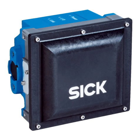
The Multi Physics Box also displays values in the frequency range (see "Vibration in the
frequency range", page 18) through a Fast Fourier transformation. This is calculated on
the vibration data of the signal axis selected via Subindex 3. If information of all 3 axes
is required, this can be implemented via the magnitude of the axes.
Magnitude =
If only one of the three axes is relevant for vibration monitoring, the sensor can be set
to single-axis operation via Subindex 1. In this case, all indication values are output
only for the axis selected in Subindex 3 (the values on the other axes are ’0’).
NOTE
The maximum block length of 1,280 ms can only be used in single-axis mode.
Signal type (Index 4477, Subindex 4)
The indication values can be calculated based on speed or acceleration values. This
selection is valid for the time range and the frequency range.
Indication values calculated based on speed weight low frequencies more heavily.
Indication values based on acceleration, on the other hand, weight higher frequencies
more heavily.
Phenomena that primarily cause vibration at frequencies up to 1,000Hz can be bet‐
ter observed with speed-based indication values. Acceleration-based indication values
should be used to detect phenomena that primarily cause higher-frequency vibrations.
Some examples are listed in table 4.
Table 4: Vibration speed and acceleration
Signal type Essential fre‐
quency range
Physical influence Application
Speed 10 ... 1,000Hz Kinetic energy and
inertia
Unbalance
Misalignment
Relaxation
Acceleration Up to 3,200Hz Dynamics and shock
forces
Mechanical wear, ball bear‐
ing damage
It should be noted that the speed-based indication values also heavily weight the
low-frequency noise. To obtain stable measured values when using this signal type,
the lower limit of the considered frequency range (Index 4478) should therefore be set
as high as possible. The minimum value for this limit is 10Hz with a block length of
640ms and is set automatically when changing to the Speed signal type. The minimum
values for this limit for the other block lengths are shown in table 5.
4 PRODUCT DESCRIPTION
14 O P E R A T I N G I N S T R U C T I O N S | MPB10 8028041/2022-08-16 | SICK
Subject to change without notice
Table 5: Lower limit of the frequency range for Speed signal type [Hz]
Block length [ms] Lower limit of the frequency range for Speed
signal type [Hz]
20 320
40 160
80 80
160 40
320 20
640 10
1280 10
Bandpass filter (Index 4478)
Which frequency ranges are to be considered can be selected using a bandpass filter.
Restricting the frequency range can, depending on the application and the component
to be monitored, provide a more precise indication of an error.
If no bandpass filter is applied, the frequency range from 0to 3,200Hz is taken into
account. When using the “ISO10816limit values" (see "Limit values based on ISO
10816 (Index 4534-4536)", page 33), the monitored frequency range is limited to
10 ... 1,000Hz according to the specifications of the standard.
4.3.3 Trigger (Index 4474-4475)
Condition monitoring requires repeatable conditions and corresponding data quality. Only
with these two prerequisites can changes in condition over time and deviation over the
course of time be detected. In applications with continuous uniform speeds, such as
pumps or fans driven by asynchronous motors, this is usually the case. The vibration
should always remain the same, no matter at what point in time it is measured during
operation. This is not the case with dynamic, non-uniform movements such as punches,
presses or motors with changing loads. Here, the data must be recorded at a specific
point in time at which a constant vibration pattern is expected (e.g. always the same
point in time in the punching process).
NOTE
When using the trigger, the number of blocks for averaging (Index 4477 Subindex 4)
should be considered and set to 1 if necessary. With a block number of 4, for example,
the trigger must fire 4 times before the values are output.
Trigger settings (Index 4474)
Recording starts with an automatic trigger immediately after the boot process. The
data blocks and the evaluations then line up seamlessly and the indication values are
updated according to the total block length (see table 2, page 13). This is the factory
setting, which is suitable for uniform, permanent movements.
If, on the other hand, recording of data is to be started at an exactly defined time, it
can be triggered via an index or via pin 2. The selection of the trigger source (automatic,
index or pin 2) is done in Index 4474, Subindex 1. If required, this trigger can be
delayed by an adjustable time (Index 4474, Subindex 3).
Trigger via an ISDU
Index 4475 can be used to trigger by writing a 1 if trigger source ISDU is selected in
Index 4474, Subindex 1.
PRODUCT DESCRIPTION 4
8028041/2022-08-16 | SICK O P E R A T I N G I N S T R U C T I O N S | MPB10 15
Subject to change without notice
Trigger via pin 2 (Index 121)
Alternatively, pin 2 can be triggered by a falling or rising signal edge or both on the
hardware side. The setting via which a signal edge is to be triggered takes place in
4474, Subindex 2. At the same time, pin 2 in Index 121 must be configured as a trigger
signal (see "Configuration of digital outputs", page 44).
4.3.4 Activity detection (Index 4479-4480)
The sensor updates the indication values even when there is no vibration. In this case,
the indication values are calculated from the noise signal of the vibration sensor. Espe‐
cially the impulse factor (see "Vibration in time range (Index 4483-4539)", page 16)
can assume very high values, which can lead to misinterpretations of the machine
condition and undesired alarms.
An applied vibration can therefore be registered via activity detection. When the func‐
tion is used, Index 4480 outputs whether an activity is detected or not.
If no vibration is detected, all current indication values are set to 0, the minimum and
maximum values are not updated. This has the advantage that, for example, the limit
value of the impulse factor is not exceeded as long as no vibration is present. Activity
detection is based on the a-RMS magnitude value (or in single-axis mode, on the a-RMS
value of the selected axis). If the a-RMS value exceeds the “activity limit” set in Index
4470 Subindex 2, an activity is recognized as such. If the a-RMS value falls below the
limit value set in Subindex 3, no activity is detected accordingly.
4.3.5 Vibration in time range (Index 4483-4539)
The Multi Physics Box, as shown in section 4.3.1, provides indication values in the time
range calculated block by block. These values provide information about the vibration
intensity and the type of vibration signal.
A total of 9 statistical and vibration-specific values are provided for interpretation. The
mathematical basis of the indication values is described below. Which error cases and
effects can represent changes of the respective characteristic values is described in
section 9.3.
a-RMS (Index 4483-4485)
a-RMS stands for acceleration - Root Mean Square. The value, given in [g = 9.81m/s2], is
the effective value of the acceleration signal and a measure of the energy contained
in the vibration. It can be used to estimate the strength of the vibration. In general, it
can be assumed that the a-RMS value is more sensitive to changes in vibration above
1,000Hz than the v-RMS value.
v-RMS (Index 4486-4488)
In line with the a-RMS, the v-RMS (velocity - Root Mean Square) in [mm/s] represents
the effective value of the speed signal. This value is also a measure of the energy
contained in the vibration. Unlike the a-RMS, the v-RMS is more sensitive to changes in
vibration below 1,000Hz than the a-RMS.
Variance (Index 4489-4491)
The variance is a statistical measure that indicates how widely the signal values are
scattered around their mean value. In the context of vibration analysis, this is a meas‐
ure of the strength of a vibration analogous to the RMS value.
4 PRODUCT DESCRIPTION
16 O P E R A T I N G I N S T R U C T I O N S | MPB10 8028041/2022-08-16 | SICK
Subject to change without notice

Skewness (Index 4491-4494)
Skewness is a statistical measure that indicates the asymmetry of the signal’s scatter
around its mean value. A change in Skewness indicates a fundamental change in the
mode of vibration.
Kurtosis (Index 4495-4497)
Kurtosis is a dimensionless parameter for the distribution of values in the acceleration
signal. The value can be used to estimate the type of vibration measured and thus
detect a change. For example, a white noise signal has a Kurtosis of 3, whereby a sine
wave has a Kurtosis of 1.5. An example is shown in figure 6, where pulses occurring in
the vibration are reflected in higher values of Kurtosis.
1
2
(m/s2)
(S)
Figure 6: Kurtosis
1Kurtosis = 7
2Kurtosis = 3
Peak to peak (Index 4498-4500)
The Peak to peak value indicates the range of raw acceleration and speed values. It is
calculated as the difference between the largest and the smallest value.
Shape factor (Index 4501-4503)
The Shape factor is defined as the ratio between the effective value of the signal and
the mean value of the absolute values of the signal. An increase in the Shape factor
indicates an increase in the amplitudes of harmonics in the signal.
Crest factor (Index 4504-4506)
The Crest factor is defined as the ratio of the Peak to peak value to the RMS value of the
signal. An increase in the Crest factor typically indicates the occurrence of pulsed signal
components.
Impulse factor (Index 4507-4509)
The impulse factor is the ratio of the Peak to peak raw values to the mean value
of the “Absolute raw values.” The value can be considered an indication of whether
brief pulses occur in the acceleration signal which are significantly stronger than the
permanent vibration.
For example, a pure sine wave has a impulse factor of 1.44. If a much stronger impulse
factor is measured for an expected sinusoidal vibration, this is an indication of pulsed
faults.
PRODUCT DESCRIPTION 4
8028041/2022-08-16 | SICK O P E R A T I N G I N S T R U C T I O N S | MPB10 17
Subject to change without notice
Calculation of the impulse factor: IF = maximum value/mean value of the absolute raw
values
1
2
Figure 7: Impulse factor example
1IF = 4.2
2IF = 1.44
4.3.6 Vibration in the frequency range
Vibration data in the frequency range in many cases allow for a much more precise
identification of vibration causes than the previously discussed time range values.
For this purpose, the vibration signal is transmitted from the time to the frequency
range by means of FFT (Fast Fourier Transformation). The information of what are the
dominant frequencies in a vibration makes it possible to better understand the cause
of the vibration. For example, the vibration of an motor always contains vibrations with
frequencies corresponding to the motor speed, but can also contain vibrations caused
by the motor bearings or electronic components such as the rectifier, which contain
other frequencies.
The acceleration or speed spectrum of the vibration can be observed through the
frequency.
The analysis in the frequency range is based on the vibration values of one axis or
the sum signal of all 3 axes (magnitude). The selection is made via the settings of
the vibration analysis (see "Settings for vibration analysis (Index 4477, 4479, 4482,
4531)", page 12).
The settings for trigger, block length and number of blocks for averaging have the
same effect on vibration analysis in the frequency range. The bandpass filter must
also be taken into account, which can restrict the frequency range under consideration
between 0.78 and 3,200Hz.
The frequency resolution is calculated with 1/block length in seconds. It specifies
both the smallest measurable frequency and the minimum frequency spacing that
two vibration components must have in order to be distinguishable in the frequency
analysis.
Table 6: Block length in relation to frequency resolution
Block length [ms] Resolution [Hz]
Smallest measurable frequency
20 50
40 25
80 12.5
160 6.25
4 PRODUCT DESCRIPTION
18 O P E R A T I N G I N S T R U C T I O N S | MPB10 8028041/2022-08-16 | SICK
Subject to change without notice
Block length [ms] Resolution [Hz]
Smallest measurable frequency
320 3.12
640 1.56
1,280 0.78
As explained in section 4.3.2, the sensor can average the spectra of several data
blocks recorded in succession, and continue to process this averaged spectrum (to
output the spectrum or to detect the peaks in the spectrum). Averaging improves the
signal-to-noise ratio in the spectrum, but the output data is updated correspondingly
less frequently.
4.4 Temperature monitoring (Index 4352-4355)
Temperature changes in the application are measured via the back of the sensor hous‐
ing. The better the thermal diffusivity of the material on which the sensor is mounted,
the more accurate the measurement.
If the sensor is non-flush or there is an adapter plate with poor temperature conductiv‐
ity between the sensor and the machine, the influence of the self-heating of the sensor
is stronger and the measured value is less accurate. Observe section 6 here.
4.5 Shock (Index 4434–4448)
In addition to the vibration sensor for vibration, there is another MEMS-based vibration
sensor for shock detection in the Multi Physics Box.
With a measuring range of up to 200g, the maximum accelerations are measured in all
three axes, thus monitoring shock events.
PRODUCT DESCRIPTION 4
8028041/2022-08-16 | SICK O P E R A T I N G I N S T R U C T I O N S | MPB10 19
Subject to change without notice
5 Transport and storage
5.1 Transport
For your own safety, please read and observe the following notes:
NOTE
Damage to the sensor due to improper transport.
■The device must be packaged for transport with protection against shock and
damp.
■Transport should be performed by specialist staff only.
■The utmost care and attention is required at all times during unloading and
transportation on company premises.
■Note the symbols on the packaging.
■Do not remove packaging until immediately before you start mounting.
5.2 Transport inspection
Immediately upon receipt at the receiving work station, check the delivery for complete‐
ness and for any damage that may have occurred in transit. In the case of transit
damage that is visible externally, proceed as follows:
■Do not accept the delivery or only do so conditionally.
■Note the scope of damage on the transport documents or on the transport compa‐
ny’s delivery note.
■File a complaint.
NOTE
Complaints regarding defects should be filed as soon as these are detected. Damage
claims are only valid before the applicable complaint deadlines.
5.3 Storage
Store the device under the following conditions:
■Recommendation: Use the original packaging.
■Do not store outdoors.
■Store in a dry area that is protected from dust.
■To allow any residual dampness to evaporate, do not package in airtight contain‐
ers.
■Do not expose to any aggressive substances.
■Protect from sunlight.
■Avoid mechanical shocks.
■Storage temperature: see "Technical data", page 55.
■Relative humidity: see "Technical data", page 55.
5 TRANSPORT AND STORAGE
20 O P E R A T I N G I N S T R U C T I O N S | MPB10 8028041/2022-08-16 | SICK
Subject to change without notice
Table of contents
Other SICK Accessories manuals

SICK
SICK OLS10 User manual

SICK
SICK W34 Series User manual

SICK
SICK MultiPulse WTB4-3P2100S14 User manual

SICK
SICK WT34 Series User manual

SICK
SICK WTB4S-3 User manual

SICK
SICK UC40-112 Series User manual

SICK
SICK LFP Inox User manual

SICK
SICK RMS1000 User manual

SICK
SICK deTem4 Core IP69K User manual

SICK
SICK Lector64x Flex User manual

SICK
SICK deTem4 Core A/P User manual

SICK
SICK KTS User manual

SICK
SICK NAV210 User manual

SICK
SICK GTB6L-P1 Series User manual

SICK
SICK GRL18 Series User manual

SICK
SICK MLS User manual

SICK
SICK OD7000 Series User manual

SICK
SICK PL240DG-H User manual

SICK
SICK LFV 200 User manual

SICK
SICK T-EASIC FTS User manual