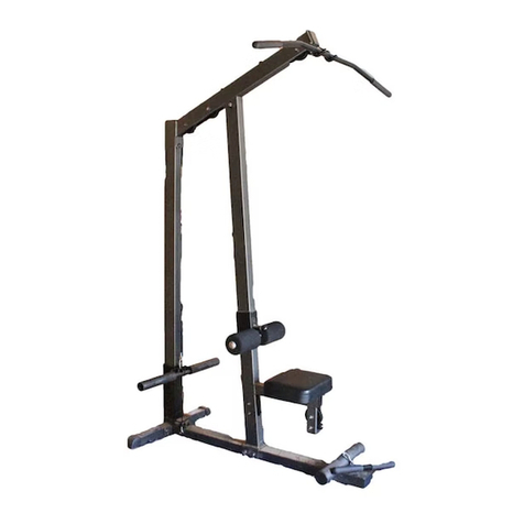
867101 LAT OPTION ASSEMBLY INSTRUCTIONS
10.
11.
12.
13..
14.
Slide the CARRIAGEdown over the LATUPRIGHTas showI1 on drawing. (MAKESU]~E THAT
THE WEIGt~T PEG ON THE. CPJ~RL&GE IS FAC][NG TOWAP~STHE FRONT OF THE
MACHINE)
15.
SECURELYassemble the UPRIGHTEXTENSIONto the top of the UPRIGHTFRAMEas shown in
(DETAILB) using one (1) 1/2 X 3 IN. BOLT,the 3/4 X1/2 X1-9/t6 IN. SPACER,two (2) 1/2
WASI-~RS,and one (1) 1/2 IN. NUT.
LOOSELYassemble three (3) 3-1/2 X 3/8 X 1 IN. PULLEYS,and six (6) 5/8 X3/8 X
SPACERSbetween the PULLEYMOUNTFLATSas shown on drawing using three (3) 3/8 X 3-1/4 IN.
BOLTS,six (6) 3/8 IN. WASHERS,and three (3) 3/8 IN. LOCKNUTS.(DONOTTIGI[TENTHE
BOLT CONNECTIONSAT T]~IS TIME)
LOOSELYassemble the two (2) PULLEYMOUNTFLATSto the LATUPRIGHT,and the
UPRIGtITEXTENSIONas shownon drawing, using two (2) 3/8 X 3-1/4 IN. BOLTS,four (4) 3/8
WASHERS,and two (2) 3/8 IN. LOCKNUTS. (DO NOT TIGHTENTHE BOLT CONNECTIONS
AT THIS TIME)
Loosen, remove, and discard the top 1/2 X 3-1/4 IN. BOLTthat connects the CROSSBRACEto the
UPRIGHTFRAME,and SECURELYassemble file LOWPULLEYSUPPORTto tile UPRIGttT
FRAMEas shownon dra~ving using one (1) 1/2 X 3-1/2 IN. BOLT,and re-using the two (2) 1/2 IN.
WASHERS,and file one 1/2 IN. LOCKNUT.
LOOSELYassemble one (1) 3-1/2 X 3/8 X 1 IN. PULLEYand orte 5/8 X 3/8 X 1/4 IN. SPACERto file
LOWPULLEYSUPPORTas shown on drawing using one (1) 3/8 X 2-1/4 IN. BOLT,two (2.) 3/8
WASHERS,and one (1) 3/8 IN. LOCKNUT. (THIS CONNECTIONWILL BE TIGIITENED
AFTER CABLE HAS BEEN ROUTED)
LOOSELYassemble two (2) 3-1/2 X 3/8 X 1 IN. PULLEYSbetween two (2) CONNECTORPLATES
as shownon drawing using two (2) 3/8 X2-1/4 IN. BOLTS,four (4) 3/8 IN. WASHERS,and two (2)
IN. LOCKNUTS. (TttIS CONNECTIONWILL BE TIGHTENEDAFTER CABLE HAS BEEN
ROUTED)
Route the first CABLE(THE ENDWITHOUTWHITEBALL)over file HIGHPULLEYof the
PULLEYMOUNTFLATS.Then assemble one (1) 3/8 X 3-1/4 IN. BOLTtwo (2) 3/8 IN. WASHERS,
m~done(l) 3/8 IN. LOCKNUTto file last hole of the PULLEYMOUNTFLATS.(DO NOTOVER
TIGHTEN BOLT) (MAKE SURE THAT THE CABLE IS BETWEENTHE PULLEY AND
BOLT)
Pull CABLEover and down the SECONDPULLEYof the PULLEYMOUNTFLATS. Rim the
CABLEaround one of the PULLEYSassembled ~o the CONNECTORPLATESfrom STEP 14, and
up to file THIRDPULLEYof the PULLEYMOUNTFLATS.
Pull CABLEover and downthe THIRDPULLEY,to file CARRIAGE.Attach the CABLEtc, the
CARRIAGE,using one (1) 5/16 IN. SNAPHOOIC
See CABLEROUTINGDIAGRAMfor help hi completing STEP 15.
504./1:;/97
