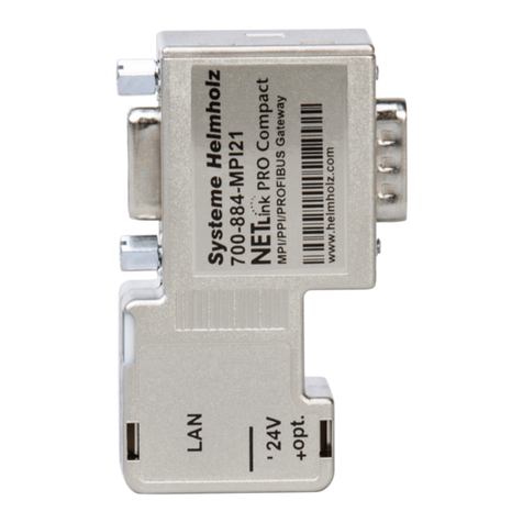
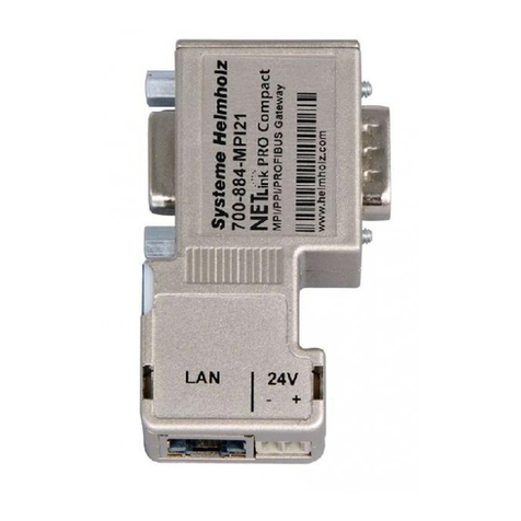
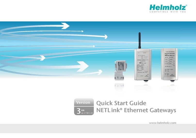
Helmholz NETLink 700-881-MPI21 User manual

Helmholz GmbH & Co. KG | Hannberger Weg 2 | D-91091 Großenseebach | Germany
Phone +49 9135 7380-0 | Fax +49 9135 7380-110 | info@helmholz.de | www.helmholz.com
Ethernet Gateways for MPI/PPI/PROFIBUS
Manual for all NETLink®Ethernet versions:
700-881-MPI21
700-882-MPI21
700-884-MPI21
Edition 3 / 16.02.2021 / ab FW 2.58
Order number of manual: 900-88X-MPI21/en

All rights are reserved, including those of translation, reprinting, and
reproduction of this manual, or parts thereof. No part of this manual
may be reproduced, processed, copied, or transmitted in any way
whatsoever (photocopy, microfilm, or other method) without the
express written permission of Helmholz GmbH & Co.KG, not even
for use as training material, or using electronic systems. All rights
reserved in the case of a patent grant or registration of a utility
model or design.
Copyright ©2009 by
Helmholz GmbH & Co.KG
Hannberger Weg 2, 91091 Grossenseebach, Germany
Note:
We have checked the content of this manual for conformity with
the hardware and software described. Nevertheless, because devia-
tions cannot be ruled out, we cannot accept any liability for com-
plete conformity. The information in this manual is regularly up-
dated. When using purchased products, please heed the latest ver-
sion of the manual, which can be viewed in the Internet at
www.helmholz.com, from where it can also be downloaded.
Our customers are important to us. We are always glad to receive
suggestions for improvement and ideas.
STEP ,Protool, TIA Portal, Starter, Micro/Win, and SIMATIC are registered trademarks of SIEMENS AG
MS-DOS and Windows are registered trademarks of Microsoft Corporation.

NETLink®Ethernet Products
3
Revision history of this document:
Edition Date Revision
1
16.06.2012
Summary of all Ethernet variants
2
16.03.2015
NETLink Switch deleted; Troubleshooting supplements
3
16.02.2021
General updates

4 NETLink®Ethernet Products
Contents
1Safety Information 7
1.1 General 7
1.2 Restriction of access 8
1.3 Information for the user 8
1.4 Use as intended 8
1.5 Avoiding use not as intended! 8
2Installation and mounting 9
2.1 Mounting orientation 9
2.2 Minimum spacing 9
2.3 Installing the module 9
2.3.1 NETLink®PRO PoE and NETLink®WLAN 9
2.3.2 NETLink®PRO Compact 9
3Overview of the System 10
3.1 Application and functional description 10
3.1.1 NETLink®PRO Poe and NETLink®WLAN 10
3.1.2 NETLink®PRO Compact 11
3.2 Connections 12
3.2.1 NETLink®PRO PoE and NETLink®WLAN 12
3.2.2 NETLink®PRO Compact 12
3.3 LED-Indicators 12
3.3.1 LEDs on the RJ45 network jack (all NETLink®versions) 13
3.3.2 General LED Indications and Connectors 13
3.3.3 LED-displays on the NETLink®PRO Compact 15
3.4 Included in Delivery 15
3.5 Accessories 15
3.5.1 Manuals 15
3.5.2 Software 15
3.5.3 Other accessories 15
3.5.4 WLAN antenna and antenna cable 16
4Installation of the driver software 17
4.1 Introduction 17
4.2 System requirements 17
4.3 Running the installation setup 17
4.3.1 Adding the interface to the PG/PC interface 18
4.3.2 Selecting the required interface parameterization 20
5Configuration via the NETLink-S7-NET Driver 21
5.1 Bus settings 21

NETLink®Ethernet Products
5
5.1.1 MPI 22
5.1.2 PROFIBUS configuration 23
5.1.3 PPI configuration 26
5.2 Local connection (TCP parameterization) 26
5.2.1 Creating a station 27
5.2.2 Setting TCP parameters 29
5.2.3 Operation without the DHCP 30
5.2.4 DHCP 31
5.2.5 Additional features 31
5.3 Options of the driver 32
5.3.1 Language setting of the display elements 32
5.3.2 Version information 32
5.4 Diagnostics 33
5.4.1 Bus members 33
5.4.2 Bus parameters 33
6The Tool: ‘NETLink®PRO Family Configuration’ 35
7Possibilities of the Web Interface 36
7.1 Home Page 36
7.2 Setting up access 36
7.3 Status Page 37
7.4 Configuration page 37
7.5 Security page 38
7.6 Observing variables 39
7.7 NETLink®WLAN configuration 39
7.7.1 NETLink®WLAN in the infrastructure mode (AP) 39
7.7.2 NETLink®WLAN in the ad hoc mode 40
7.7.3 Connection establishment PC to NETLink®WLAN in the
unencrypted ad hoc mode 40
7.7.4 Connection establishment PC to NETLink®WLAN in the
encoded ad hoc mode 42
8RFC1006-Function (S7-TCP/IP) 46
8.1 CPU Addressing with Rack/Slot and TSAP 46
9Bus Parameters in Single Master Operation 48
9.1 Storing specified bus parameters 48
9.2 Addressing with Routing over RFC 49
9.2.1 RFC Multicomputing with TSAP 50
9.2.2 RFC Routing over CP with TSAP 50
10 Troubleshooting 52
11 Appendix 56

6 NETLink®Ethernet Products
11.1 General technical Data 56
11.1.1 Technical Data NETLink®PRO PoE 56
11.1.2 Technical Data NETLink®WLAN 56
11.1.3 Technical Data NETLink®PRO Compact 57
11.2 Pin assignments 57
11.2.1 MPI/PROFIBUS interface pin assignments 57
11.2.2 Assignment of the Ethernet interface (host interface) 57
11.2.3 Power supply socket 57
11.3 Further documentation 58
11.3.1 Information in the internet 58
11.3.2 Further information 58
11.3.3 Address conversion table 59
12 Glossary 60

NETLink®Ethernet Products
7
1Safety Information
For your own safety and for the safety of others, always heed the
safety information given here. The safety information indicates
possible hazards and provides information about how you can
avoid hazardous situations.
The following symbols are used in this manual.
Caution, indicates hazards and sources of error
Gives information
Hazard, general or specific
Danger of electric shock
1.1 General
A NETLink®Gateway is only used as part of a complete system.
The operator of a machine system is responsible for observing
all safety and accident prevention regulations applicable to the applica-
tion in question.
During configuration, safety and accident prevention rules spe-
cific to the application must be observed.
Emergency OFF facilities according to EN 60204 / IEC 204
must remain active in all modes of the machine system. The system
must not enter an undefined restart.
Faults occurring in the machine system that can cause damage
to property or injury to persons must be prevented by additional exter-
nal equipment. Such equipment must also ensure entry into a safe state
in the event of a fault. Such equipment includes electromechanical
safety buttons, mechanical interlocks, etc. (see EN 954-1, risk assess-
ment).
Never execute or initiate safety-related functions using an
operator terminal.

8 NETLink®Ethernet Products
1.2 Restriction of access
The modules are open equipment and must only be installed in
electrical equipment rooms, cabinets, or housings. Access to the
electrical equipment rooms, barriers, or housings must only be
possible using a tool or key and only permitted to personnel
having received instruction or authorization.
1.3 Information for the user
This manual is addressed to anyone wishing to configure, use, or
install a NETLink®Gateway.
The manual tells the user how to operate the NETLink®and
explains the signaling functions. It provides the installing
technician with all the necessary data.
The NETLink®Gateways are exclusively for use with a S7-200 and
S7-300/S7-400 programmable controller from Siemens.
A NETLink®is for use within a complete system only. For that
reason, the configuring engineer, user, and installing technician
must observe the standards, safety and accident prevention rules
applicable in the particular application. The operator of the
automation system is responsible for observing these rules.
1.4 Use as intended
These NETLink®Gateways must only be used as a communication
and signaling system as described in the manual.
1.5 Avoiding use not as intended!
Safety-related functions must not be controlled via a NETLink®
alone. Make sure in the software that uncontrolled restarts cannot
occur.
Only authorized persons
must have access to the
modules!
During configuration,
safety
and accident
prevention rules specific
to the application must
be observed.
Make sure in the
software that
uncontrolled restarts
cannot occur.

NETLink®Ethernet Products
9
2Installation and mounting
Installation and mounting must be carried out in accordance with
VDE 0100 / IEC 364. As this is an IP20 module, it must be
installed in a cabinet.
A maximum ambient temperature of 60 ºC must be ensured for
reliable operation.
2.1 Mounting orientation
All NETLink®can be installed in any orientation.
2.2 Minimum spacing
By maintaining minimum spacings
•then NETLink®Gateways can be inserted and removed
without having to remove other system components.
•there is sufficient space to connect existing interfaces and
other contacts using standard commercial type accessories.
•there is room for any necessary cable routing.
For a NETLink®PRO PoE, NETLink®Switch and a NETLink®WLAN
a minimum clearance of 60 mm must be left above and below
and 10 mm at the sides.
2.3 Installing the module
2.3.1 NETLink®PRO PoE and NETLink®WLAN
A wall/DIN rail bracket is available as an accessory for mounting
on flat surfaces or on DIN rails.
The accessories available are listed in Section 3.5, together with
the corresponding order numbers.
2.3.2 NETLink®PRO Compact
The NETLink®PRO Compact is plugged directly into the SUB D
female connector of the PROFIBUS station instead of the standard
PROFIBUS device connector. It is fixed using the permanently in-
tegrated hexagon-head housing screws and therefore makes per-
manent contact.
Further bus nodes for diagnostic devices can be connected to the
integrated PG female connector.
Only CAT5-TCP cables with an RJ45 connector can be connected
to the NETLink®PRO Compact housing. No further outlets, for
example, PROFIBUS cable, can be installed on the device. There-
fore no termination is possible on the connector housing and the
"ON/OFF" switch for this is not been incorporated.
Before you start
installation work, all
system components
must be disconnected
from their power source.

10 NETLink®Ethernet Products
3Overview of the System
3.1 Application and functional description
The NETLink®is a gateway between a TCP network and an MPI,
PPI, or PROFIBUS network.
Two protocols are available on the TCP side for the exchange of
user data with the automation system:
•one is a proprietary protocol that is used to connect to the
proprietary NETLink-S7-NET driver, and
•the other is the S7-TCP/IP protocol often used by visualization
system manufacturers which is known as ‘RFC1006’ or ‘ISO on
top of TCP'.
Up to 16 TCP connections (10 Mbps or 100 Mbps) and up to 32
MPI/PPROFIBUS connections (9.6 Kbps to 12 Mbps) can be used
simultaneously.
The TCP/IP end of the NETLink®is electrically isolated from the
MPI/PPI/PROFIBUS.
On both the TCP and the field bus sides, the baud rate used can
be determined automatically (auto negotiation resp. auto baud).
Internet tele servicing with NETLink®products should only take
place through additional encoding mechanisms and the usual se-
curity criteria. The usual VPN technology (Virtual Private Net-
work) is suitable for this purpose. Further components are neces-
sary to incorporate a NETLink®gateway into such a virtual tunnel.
3.1.1 NETLink®PRO Poe and NETLink®WLAN
The connecting cable used to link the NETLink®Gateway with the
programmable controller is 1.2 meters long and active. Because it
is active, no spur lines are required which could interfere with the
bus.
These NETLink®devices can draw the necessary power from either
the bus interface of the programmable controller or via an
external power supply.
In addition to the wired TCP/IP connectivity the NETLink®WLAN
has a built-in Wi-Fi module. The adapter can establish a
connection to an access point via the so called “Infrastructure
Mode”. In addition it is possible to establish a direct connection to
a PG/PC using the so called “AdHoc Mode”. NETLink®WLAN
supports WLAN standards 802.11 b/g. Therefore, data rates of up
to 54 Mbps are possible.
The NETLink®PRO PoE is a Powered Device (PD) according to the
IEEE 802.3af (POE) and IEEE 802.3at (POE+) standards. This is the
generally accepted term for technology that supplies devices with
power via a commercially available 8 wire RJ 45 Ethernet cable.
This standardisation ensures worldwide compatibility and high
flexibility when used in PoE installations; for example, that is
affected by neither transmission capacity nor range (even in
Added feature ‘Power over
Ethernet’ according to the
IEEE 802.3af standard
The TCP/IP communic
a-
tion
is not encoded to the
extent that no direct IP
Internet tele servicing
should take place via a
NETLink® gateway.
NETLink®Ethernet Products
11
existing networks). The power supply is assured by the Power
Source Equipment (PSE). This type of switch, hub or power
injector supports the Resistive Power Discovery which ensures
that the power delivered via the LAN is only activated when a
compatible end-device such as NETLink®PRO PoE has been
detected, the 48 V supply is automatically blocked when none-
PoE Ethernet devices are detected. In this way both conventional
and PoE-compatible devices can be used together in connection
with the energy supply devices described above.
As can be seen in the pin assignment of the NETLink®PRO PoE
network connector, the energy supply is fed via the Spare-Pair
wire pairs 4/5 and 7/8, ensuring that the 4 remaining data transfer
wires are not affected. In addition, dependent on the PSE unit in
use, the existing wiring can be used for distributing power. Using
the Phantom Power the power supply is ensured through its
superimposition on the data signals. The NETLink®PRO PoE
automatically recognises the current technique and can therefore
be used with all types of PSE.
In addition the specification mandates that the PD can be
supplied over up to 100 metres of cable without a repeater. In
order to ensure that the distribution resistance (and the resulting
power loss) is minimised to the greatest possible extent, excessive
use of plug/socket extension elements should be avoided where
possible.
The connection between PSE and PD can be either a straight or a
cross-over cable. Using special input switching, the NETLink®PRO
PoE recognises the actual polarity.
The external feed or the bus interface of the automation system
have priority for the external 24 V supply to the NETLink®PRO
PoE. If one of these fails, PoE is used as a reserve. Due to the
internal switchover the device automatically carries out a reset.
Further important concepts behind Power over Ethernet are
described in the glossary (Section 12).
3.1.2 NETLink®PRO Compact
The NETLink®PRO Compact has the shape of a PROFIBUS con-
nector with a PG female connector and it is plugged directly into
the MPI/PPI/PROFIBUS interface of the automation system. Be-
cause it is active, no spur line is created that could interfere with
the bus. The TCP/IP end of the NETLink®PRO Compact is elec-
trically isolated from the MPI/PPI/PROFIBUS.
On both the TCP and the field bus sides, the baud rate used can
be determined automatically (auto negotiation or auto baud)
The NETLink®PRO Compact can draw the necessary power supply
either from the bus interface of the programmable controller or
via an external power supply.
The use of the NETLink-S7-NET driver makes it possible to use the
NETLink®Gateways as the following at the PC end

12 NETLink®Ethernet Products
•Programming adapter, or
•Operator control and monitoring unit
The RFC1006 interface also enables you to use third-party soft-
ware that supports this protocol to communicate with S7-200/S7-
300 and S7-400 systems.
A NETLink®can generally be connected to the PC via a switch,
hub or directly via LAN cable.
3.2 Connections
All NETLink®devices have the following connections:
•RJ45 female connector for connecting the supplied standard
CAT5-TCP cross-over cable. The automatic interface detection
“Auto - (MDI) X” means that switches and computer direct
connections can be used with this cable type. A separate
converter is not required.
•Power supply socket for 24 V DC power supply.
This power supply option can be used optional (except of the
NETLink®switch), if the used programmable controller does
not provide any or only insufficient power on the bus
connector.
3.2.1 NETLink®PRO PoE and NETLink®WLAN
These versions included a bus connector with programming unit
female connector, switchable terminating resistor, and 1.2 m
connecting cable. This is an ‘active cable.’ This means there is no
spur line, thus avoiding interference on the bus at high baud
rates. The programming unit female connector of the bus
connector allows further bus nodes to be plugged in. The
terminating resistor must be inserted (ON) if these NETLink®
devices are plugged in at the start or end of a bus segment. If this
is not the case, the switch must be in the OFF position.
•The NETLink®WLAN contains in addition a SMA socket for
connection to a customary WLAN antenna (for accessories, see
Section 3.5).
•The NETLink®PRO PoE can also be supplied via an Powered
Ethernet switch/router, which may deliver the 48 volt supply
to the RJ45 connector. Further information about Power over
Ethernet is explained in Section 3.1.1.
3.2.2 NETLink®PRO Compact
The NETLink®PRO Compact is completely embedded in a bus
connector. This compact device represents also an ‘active cable’,
which means there is no spur line which avoids interference with
higher baud rates.
3.3 LED-Indicators
All NETLink® Gateways come with several bi-colored LEDs to
indicate the operating status.
All NETLink have the IP
address 192.168.4.49 on
delivery from the factory
.

NETLink®Ethernet Products
13
3.3.1 LEDs on the RJ45 network jack (all NETLink®versions)
The two LEDs which are located on each RJ45 female connector
indicate by their status the current state of the TCP network:
LINK LED (green)
ACTIVE LED (yellow)
Status
Description
Status
Description
OFF
Not connected
OFF
No activity on the network
ON
Connected
ON
Activity on the network
BLINK
BLINK Activity on the network
3.3.2 General LED Indications and Connectors
The three LEDs (two two-colored LEDs) on the top of the
NETLink®indicates the operating status of the device itself:
LED status versus
operating status
Power
LED
(green)
Active
LED
(green)
Active
LED
(red)
Connect
LED
(green)
Connect
LED
(red)
Seeking for
network partner
and TCP
configuration
BLINK
Ready for
operation ON
Expects MPI / PPI /
PROFIBUS
parameters for
login
ON BLINK
Actively logged on
to the
MPI/PPI/PROFIBUS
ON ON
Active connection
to an automation
system
ON ON ON
Data exchange
with an
automation system
ON ON BLINK
Transferring
firmware update BLINK BLINK BLINK
Storing firmware
update ON ON ON
Bus side exception
error ON BLINK
Programming
unit/PC side
exception error
ON BLINK
Lights or blinks only the
yellow LED, then the
respective port is set to 10
Mbps.

14 NETLink®Ethernet Products
LEDs and connectors on the NETLink®PRO PoE:
The NETLink®WLAN has two extra LEDs on the top of the case,
which indicate the operating status of the wireless connection:
DIAG LED (yellow)
ACTIVE LED (green)
Status
Description
Status
Description
OFF
No Errors (WLAN)
OFF
No WLAN connection
ON Wi-Fi module damaged ON/BLINK Connection established
BLINK
Read/write Configu-
ration BLINK
Try to attempt a WLAN
connection
LEDs and connectors on the NETLink®WLAN:

NETLink®Ethernet Products
15
3.3.3 LED-displays on the NETLink®PRO Compact
The NETLink®PRO Compact has two multi-colored LEDs. These
are located on the front of the housing behind a white inspection
window.
LED status for operating
status
Power LED
(blue)
Bus LED
(orange)
Active LED
(green)
Bus LED
(red)
Seeking for network
partner and TCP
configuration
BLINK
Ready for operation
ON
Expects MPI/PPI/PROFI-
BUS parameters for login ON BLINK
Actively logged on to the
MPI/PPI/PROFIBUS ON ON
Data exchange with a
programmable controller ON BLINK
Transferring firmware
update ON BLINK
3.4 Included in Delivery
The following is delivered with each NETLink®device:
•NETLink®ready for operation
•CAT5 TCP cable (cross-over) with a length of 3 meters
•label with QR codes and relevant download links
3.5 Accessories
3.5.1 Manuals
The current version is available for download at
www.helmholz.de.
3.5.2 Software
With the help of our freely available diagnostics and update soft-
ware SHTools, you can, for example, carry out firmware updates
yourself. In order to ensure the complete functional scope of your
NETLink®adapter, we recommend that you regularly update your
devices. The most recent version is available for download at
www.helmholz.de.
3.5.3 Other accessories
DIN rail bracket for NETLink®WLAN 700-751-HSH10
DIN rail bracket for NETLink®PRO PoE 700-751-HSH01
The DIN rail bracket is for mounting the NETLink®on DIN
rails. It can also be used as a wall bracket for mounting on flat
surfaces.
The DIN rail bracket and NETLink®can be separated without
the use of tools.
Mains power adapter 700-751-SNT01
All NETLink have the IP
address 192.168.4.49 on
delivery from the factory
.

16 NETLink®Ethernet Products
Input: AC 100-240 V /Output: DC 24 V
You can find additional technical data at www.helmholz.de
Active PROFIBUS plug cable 3m 700-901-4BD00
3.5.4 WLAN antenna and antenna cable
2,4 GHz 5 dBi magnetic base antenna
(With 1m cable) 700-889-ANT01
2,4 GHz 8 dBi Omni antenna
(Required cable see below) 700-889-ANT02
2,4 GHz 8 dBi Panel antenna
(Required cable see below) 700-889-ANT03
Antenna cable, 3 m; 1,7 dB Ø 2,5 mm 700-889-ANK01
Antenna cable, 5 m; 2,8 dB Ø 2,5 mm 700-889-ANK02
Antenna cable, 6 m; 1,4 dB Ø 10 mm 700-889-ANK03
Antenna cable, 10 m; 2,3 dB Ø 10 mm 700-889-ANK04

NETLink®Ethernet Products
17
4Installation of the driver software
With installation of the NETLink-S7-NET driver for NETLink®
Gateways, it is easy to access controllers with a
MPI/PPI/PROFIBUS interface from the PC via TCP/IP.
4.1 Introduction
The NETLink-S7-NET driver is inserted in the PG/PC interface of
an existing Simatic application and can then be used from most
Simatic engineering tools (STEP7, ProTool, WinCC, etc.).
Access is possible to any controllers of the Simatic S7-200, S7-300,
or S7-400 series via a NETLink®Gateway.
4.2 System requirements
A PC with a 32/64 Bit Microsoft operating system with adminis-
trative rights is required for the installation and operation of the
current NETLink-S7-NET driver on the PG side. The functionality
has been successfully tested with Windows XP/2003R2/7/2008R2
/8.1/2012 R2/10.
A further requirement is the existence of a Simatic engineering
tool, which ensures that the PG/PC interface is installed on the
computer.
The most recent driver version was tested with:
Siemens TIA Portal from V13 and higher
SIMATIC Manager from version 5.5 and higher
and STEP7 Micro/Win as of version 4.0.
Installation under Windows 98/ME/NT operating systems is
possible but is not supported by the technical support team of
Helmholz GmbH & Co.KG. Please pay attention to the require-
ments of the Simatic package used.
A functioning network link using TCP/IP must have been set up
on the PCs that are used.The network configuration of the PC
must be known. Commercially network cards and, for the con-
nection, cross-over- or 1:1 (straight) cables may be used.
The integrated auto-negotiation function automatically negotiates
the TCP/IP transmission speed between the stations. In this way,
the best performance is achieved in a local 100 Mbps network.
Status operation will be slowed down if older 10 Mbps network
cards and hubs are used.
4.3 Running the installation setup
If necessary, you can download the latest NETLink-S7-NET driver
from our homepage (http://www.helmholz.de).
Please note that for installation you have to log on as an adminis-
trator under the 32-bit Windows operating systems because the
setup program has to make entries in the Windows registry.
Administration rights
are required for
installation.
We also recommend
right
-clicking on the
setup program icon and
selecting: "Execute as
administrator"

18 NETLink®Ethernet Products
When installing the program on Windows 7 operating systems,
make sure to not only log in with the Administrator account, but
to also run the program setup file using the “Run as administra-
tor” option!
For more detailed information, please refer to the relevant NET-
Link Quick Start Guide.
4.3.1 Adding the interface to the PG/PC interface
After initial installation, the new interface parameter set ‘NET-
Link-S7-NET’ has to be set up. Administrator rights are necessary
for this.
Start the program module 'Set PG/PC Interface' with the Control
Panel of your Windows PC. When the 'Select...' button is dis-
played under Add/remove interfaces, click it.
This installation step is
not needed in Windows
7 operating systems. If
you are using a compu
t-
er with
Windows 7,
please skip ahead to the
next section.

NETLink®Ethernet Products
19
This opens the ‘Install/uninstall interface’ dialog box.
After you have selected the entry ‘NETLink-S7-NET PRO family’
from the left-hand list, click the ‘Install-->’ button.
The ‘NETLink-S7-NET PRO’ has now been included in the selec-
tion list so that it is available for selection in future.
The access path in the ‘Set PG/PC Interface’ dialog box is set when
this window is closed.

20 NETLink®Ethernet Products
4.3.2 Selecting the required interface parameterization
The selection list for the interface parameter sets now contains an
additional three items for NETLink®PRO Family.
All relevant settings of a NETLink-S7-NET driver can be made via
the "Properties" access field. With the button ‘Diagnostics...’ it is
possible to show the nodes connected to the bus and the parame-
ters the bus is working with. These fields are explained in Section
5.
This manual suits for next models
2
Table of contents
Other Helmholz Gateway manuals

Helmholz
Helmholz 700-672-PNC01 User manual

Helmholz
Helmholz WALL IE 700-860-WAL01 User manual

Helmholz
Helmholz 700-671-PNC01 User manual

Helmholz
Helmholz PN/CAN gateway User manual

Helmholz
Helmholz PN/CAN Gateway Layer 2 User manual

Helmholz
Helmholz PN/CAN gateway User manual

Helmholz
Helmholz 700-670-PNC01 User manual

Helmholz
Helmholz CANopen User manual

Helmholz
Helmholz PN/CAN gateway User manual

Helmholz
Helmholz NETLink PRO Compact User manual