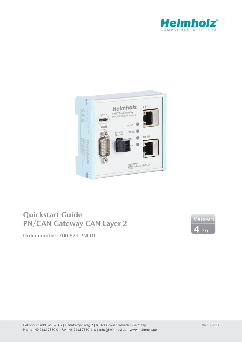
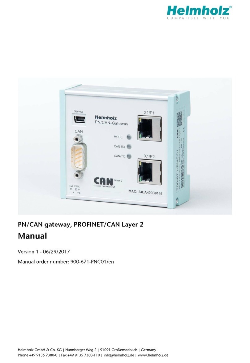
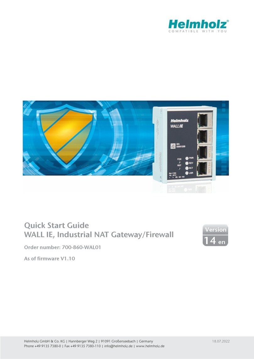
Helmholz WALL IE User manual

Quick Start Guide WALL IE
www.helmholz.com
Version
1
www.helmholz.com
en
ab FW 1.00

Quick Start Guide WALL IE2
Inhalt
1. Introduction 3
2. Connection 3
3. Initial access to the web interface 4
4. Adjustment of the IP addresses 5
5. The bridge mode 6
6. Packet lter functionality 7
7. NAT operating mode 9
8. Basic NAT 10
9. NAPT 11
10. Port forwarding 12
11. Static routes 14
12. Resetting to factory settings 15
13. LED status information 16
14. Technical data 16

Quick Start Guide WALL IE 3
1. Introduction
Please note: Please observe the safety instructions for the product, which can be found
in the manual. It can be downloaded from the website www.helmholz.com in the
download area.
This document should explain the initial commissioning of the WALLIE on the basis of
simple examples from network technology.
FCN: Function Button
Mini USB:
Service Interface
RST: Reset Button
P1: WAN Port
P2—P4: LAN Ports
Voltage Supply Operation LEDs (see page 16)
2. Connection
The WALL IE is connected with 24V DC voltage via the 5-pin power supply socket.
The RJ45 „P1 WAN“ socket is for the connection of the external network. The RJ45
„P2 LAN—P4 LAN“ sockets are switched and are for the connection of the internal
network.

Quick Start Guide WALL IE4
3. Initial access to the web interface
The WALL IE is set on the LAN-side at the factory with the IP address 192.168.0.100
and the subnet mask 255.255.255.0. Access to the web interface is only possible via
the LAN connections P2- P4.
First the IP address of your network card must be adapted to the IP subnet of the
WALL IE under „Start Control panel Network and share settings Adapter
settings LAN connection Properties Internet protocol version 4“.
Now connect a patch cable with the LAN connection of your PC and one of the LAN
ports P2—P4 of the WALL IE. The web interface can be reached in the default setup
by calling up https://192.168.0.100 in the browser page.
Note: For security reasons, the web interface can only be reached through a secured
HTTPS connection. An exception needs to be conrmed once in order to reach the
website.
A certicate for the connection backup can be stored in the „Device/HTTPS“ menu.

Quick Start Guide WALL IE 5
You will be prompted to set a password with the initial registration. With the „Con-
tinue“ button, the password is stored in the device and you will be forwarded to the
„Overview“ page of the WALLIE.
The main user is always „admin“. Another user administration hasn‘t been imple-
mented yet.
Note: Please memorize the password!
For security reasons there is no possibility to reset the password without performing a
factory reset.
4. Adjustment of the IP addresses
Click on the „Network“ menu and select the sub-menu „Interface“. The desired IP
addresses (LAN/WAN IP) and subnet masks (LAN/WAN net mask) can be dened
here. The entry is saved with the „Save“ button.

Quick Start Guide WALL IE6
5. The bridge mode
In the bridge operating mode, WALL IE behaves like a layer 2 switch between the
automation cell (LAN) and the production network (WAN). The packet lter can be
used to limit access between the two areas.
This enables the separation of a part of the production network without using diffe-
rent network adresses.
0
1
2
3
4
5
6
7
0
1
2
3
4
5
6
7
0
1
2
3
4
5
6
7
0
1
2
3
4
5
6
7
0
1
2
3
4
5
6
7
0
1
2
3
4
5
6
7
0
1
2
3
4
5
6
7
0
1
2
3
4
5
6
7
0
1
2
3
4
5
6
7
0
1
2
3
4
5
6
7
0
1
2
3
4
5
6
7
0
1
2
3
4
5
6
7
0
1
2
3
4
5
6
7
0
1
2
3
4
5
6
7
0
1
2
3
4
5
6
7
Machine network 10.10.1.0/24
10.10.1.0/24
Internal (LAN)
External (WAN)
Company network
10.10.1.30 10.10.1.31 10.10.1.50 10.10.1.100
10.10.1.32
10.10.1.10 10.10.1.20

Quick Start Guide WALL IE 7
Switch the WALL IE to the bridge mode via „Device Operating Mode Bridge“.
In the bridge mode, the IP address of the WAN interface is the same as the IP address
of the LAN interface. It is thus transparent.
The data transfer from LAN WAN is always permitted.
The data transfer from WAN LAN can be controlled with the packet lters.
6. Packet lter functionality
The packet lters enable the limitation of access between the production network
(WAN) and the automation cell (LAN). For example, it can be congured that only
certain participants from the production network can exchange data with dened
participants from the automation cell.
The following lter criteria on layers 3 and 4 are available: IPv4 addresses, protocol
(TCP/UDP), ports. The layer 2 criteria „MAC addresses“ and „Ethertype“ are in
development.
Creation of rules in the packet lter
Select „WAN to LAN“ in the „Packet Filter“ menu. The standard is that no rule is
entered and thus no access by the external network (WAN) to the internal network
(LAN) is possible in the „Bridge“ operating mode. Full access of the WAN to the LAN
is generally initially allowed in the „Basic NAT“ operating mode (see chapter 8), but
restrictions can be created with packet lters.
A PC with the IP adress 10.10.1.10 (a STEP17 programmer) should now allow access
to the CPU with the IP adress 10.10.1.30 via port 102 with the TCP protocol. To this
purpose, the following rule should be entered and saved with the button:

Quick Start Guide WALL IE8
The PC with the IP adress 10.10.1.20 (an observer) should continue to allow access to
the web interface of the panel with the IP-Adress 10.10.1.50 via port 80 with the TCP
protocol. The completely entered rules should appear as follows:
Source IP Access to this IP address of the external network (WAN) is allowed.
Destination IP Access to this device IP address of the internal network (LAN) is allowed.
Protocol Selection of the permitted protocol, TCP or UDP.
Destination Port The device port in the internal network.
Action Packets from the external network (WAN) can be permitted („Accept“) or rejected („Reject“ / „Drop“)
„Drop“ rejects a packet muted and „Reject“ responds with an ICMP error message.
Comment A comment can be entered here.
Status Rule active (A click on the lamp changes the status.)
Rule inactive (A click on the lamp changes the status.)
Deletes a rule
Adds a rule

Quick Start Guide WALL IE 9
7. NAT operating mode
When several automation cells with the same address range are to be incorporated
into a production network, this can result in collisions, as the addresses in the entire
network are not unambiguous. Using Network Address Translation (NAT), WALLIE
makes it possible to incorporate several automation cells into the production net-
work.
In the NAT operating mode, WALL IE forwards the data transfer between various IPv4
networks (Layer 3) and implements the IP addresses with the help of NAT. The packet
lter can also be used.
0
1
2
3
4
5
6
7
0
1
2
3
4
5
6
7
0
1
2
3
4
5
6
7
0
1
2
3
4
5
6
7
0
1
2
3
4
5
6
7
Machine 1
192.168.10.0/24
10.10.1.0/24
0
1
2
3
4
5
6
7
0
1
2
3
4
5
6
7
0
1
2
3
4
5
6
7
0
1
2
3
4
5
6
7
0
1
2
3
4
5
6
7
Machine 2
192.168.10.0/24
0
1
2
3
4
5
6
7
0
1
2
3
4
5
6
7
0
1
2
3
4
5
6
7
0
1
2
3
4
5
6
7
0
1
2
3
4
5
6
7
Machine X
192.168.10.0/24
Internal
External
Company network
Internal
External
Internal
External

Quick Start Guide WALL IE10
Setting up „Basic NAT“ rules
In order that the entry of „Basic NAT rules“ is possible, WALL IE must be in the opera-
ting mode „NAT“. Select the „NAT“ menu and the sub-menu „Basic NAT“. Enter the
rst rule and save it with the button
Each entry is con rmed with „Rule added successfully“.
Note: For a Basic NAT rule, all ports are always open for this data transfer! Packet lter
rules should be created to restrict access.
8. Basic NAT
Basic NAT, also known as „1:1 NAT“ or „Static NAT“, is the translation of individual IP
addresses or of complete address ranges.
The translation takes place exclusively at the IP level, which means that all ports can
be addressed without explicit forwarding.
0
1
2
3
4
5
6
7
0
1
2
3
4
5
6
7
0
1
2
3
4
5
6
7
0
1
2
3
4
5
6
7
0
1
2
3
4
5
6
7
0
1
2
3
4
5
6
7
0
1
2
3
4
5
6
7
0
1
2
3
4
5
6
7
0
1
2
3
4
5
6
7
0
1
2
3
4
5
6
7
0
1
2
3
4
5
6
7
0
1
2
3
4
5
6
7
0
1
2
3
4
5
6
7
0
1
2
3
4
5
6
7
0
1
2
3
4
5
6
7
Machine network 192.168.10.0/24
10.10.1.0/24
Internal (LAN)
External (WAN)
Company network
192.168.10.1 192.168.10.2 192.168.10.50 192.168.10.100
192.168.10.5
10.10.1.10 10.10.1.20
Machine IP
192.168.10.1
192.168.10.2
192.168.10.5
192.168.10.50
192.168.10.100
10.10.1.11
10.10.1.12
10.10.1.13
10.10.1.14
10.10.1.15
Virtual IP

Quick Start Guide WALL IE 11
External IP The virtual IP address accessible in the external network (WAN).
Internal IP The real IP address accessible in the internal network (LAN).
Comment Freely denable comment.
Status Rule active (A click on the lamp changes the status.)
Rule inactive (A click on the lamp changes the status.)
Action Deletes a rule
Adds a rule
9. NAPT
„NAPT for LAN to WAN trafc“ replaces the sender addresses of queries from the
automation cell with the address of the WALL IE („Source NAT“).
If the option is deactivated, the query packets are forwarded to the WAN with their
original sender IPs.

Quick Start Guide WALL IE12
10. Port forwarding
With the help of port forwarding („Port forwarding for WAN to LAN traf c“), it can
be con gured that packets at a certain TCP/UDP port of the WALL IE (WAN) can
be forwarded to a participant in the automation cell (LAN) (e.g. 10.10.1.1:81 to
192.168.10.1:80).
0
1
2
3
4
5
6
7
0
1
2
3
4
5
6
7
0
1
2
3
4
5
6
7
0
1
2
3
4
5
6
7
0
1
2
3
4
5
6
7
0
1
2
3
4
5
6
7
0
1
2
3
4
5
6
7
0
1
2
3
4
5
6
7
0
1
2
3
4
5
6
7
0
1
2
3
4
5
6
7
0
1
2
3
4
5
6
7
0
1
2
3
4
5
6
7
0
1
2
3
4
5
6
7
0
1
2
3
4
5
6
7
0
1
2
3
4
5
6
7
Machine network 192.168.10.0/24
10.10.1.0/24
Internal (LAN)
External (WAN)
Company network
192.168.10.1 192.168.10.2 192.168.10.50 192.168.10.100
192.168.10.5
10.10.1.10 10.10.1.20
Machine IP:Port
192.168.10.1:80
192.168.10.2:102
192.168.10.5:80
10.10.1.1:80
10.10.1.1:102
10.10.1.1:81
Virtual IP:Port
10.10.1.1
192.168.10.200

Quick Start Guide WALL IE 13
Protocol TCP/UDP
External Port The WAN port under which frames are received.
Internal IP The real IP address accessible in the internal network (LAN).
Internal Port The real IP port of the device accessible in the internal network (LAN).
Comment Freely denable comment.
Status Rule active (A click on the lamp changes the status.)
Rule inactive (A click on the lamp changes the status.)
Action Deletes a rule
Adds a rule

Quick Start Guide WALL IE14
11. Static routes
Static routes are used for communication with other automation cells. To this pur-
pose, the network and the address of the router or WALLIE responsible for this („Next
Hop“) must be con gured.
0
1
2
3
4
5
6
7
0
1
2
3
4
5
6
7
0
1
2
3
4
5
6
7
0
1
2
3
4
5
6
7
0
1
2
3
4
5
6
7
Machine 1
10.10.0.0/24
0
1
2
3
4
5
6
7
0
1
2
3
4
5
6
7
0
1
2
3
4
5
6
7
0
1
2
3
4
5
6
7
0
1
2
3
4
5
6
7
Machine 2
192.168.20.1
Internal Internal
External
192.168.20.2192.168.10.1 192.168.10.2
10.0.0.100 10.0.0.105
WAN
Production network
LAN
Automation cell
Static route:
192.168.10.x via 10.0.0.100
Static route:
192.168.20.x via 10.0.0.105
Static routes are only supported in the NAT operating mode. A static route can
be set up via „Network Static route“. In the example above, the static route to
the right WALL IE with the IP 10.0.0.105 is entered in the left WALL IE for queries to
192.168.20.x.
The procedure is con rmed with „Rule added successfully“ and the route is active.

Quick Start Guide WALL IE 15
Network The IP network to be routed from the WALL IE.
Netmask The afliated subnet mask.
Next Hop The next responsible router or WALLIE for this network.
Comment Freely denable comment.
Status Rule active (A click on the lamp changes the status.)
Rule inactive (A click on the lamp changes the status.)
Action Deletes a rule
Adds a rule
Note: In the case of devices in the internal network (LAN) that should reach other net-
works, the LAN IP address of the WALL IE is entered as a gateway.
If the opposite side of the static route is also a WALL IE, a static route for the return path
must also be entered there.
The conducting of the response frame must also be entered in the „Packet lter/WAN to
LAN“.
12. Resetting to factory settings
In order to reset WALL IE to the delivery status, the „FCN“ button must be activated
while the device is restarted. A restart can be carried out with Power OFF/ON, by
activating the RST button or with the „Device reboot“ function at the website.
The successful resetting of the parameters and settings is acknowledged during the
boot process by the USR-LED lighting up.

Notes:
The contents of this Quick Start Guide have been checked by us so as to ensure that they match the hardware and software described. However, we assume no liability for any existing differences, as these cannot
be fully ruled out.
The information in this Quick Start Guide is, however, updated on a regular basis. When using your purchased products, please make sure to use the latest version of this Quick Start Guide, which can be viewed
and downloaded on the Internet at www.helmholz.de.
Our customers are at the center of everything we do. We welcome all ideas and suggestions.
1) STEP is a registered trademark of Siemens AG.
Systeme Helmholz GmbH | Hannberger Weg 2 | 91091 Großenseebach | Germany | Phone +49 9135 7380-0 | Fax +49 9135 7380-110 | [email protected] | www.helmholz.com
13. LED status information
PWR
Off
On
No power supply or device defective
Device is correctly supplied with voltage
RDY
On
Device is ready to operate
CON
Flashing light or On
Permitted data transfer between WAN and LAN
USR
On
Factory settings reset active
RJ45-LEDs
Green (Link)
Orange (Act)
Connected
Data transfer at the port
14. Technical data
Order no. 700-860-WAL01
Interfaces 1x WAN 10/100 Mbps
3x LAN 10/100 Mbps, switch
USB 2.0, mini USB (Service)
Operating modes Bridge, Basic NAT, NAPT
Packet lter IPV4 addresses, protocol (TCP/UDP), ports,
MAC addresses (in development),
Ether types (in development)
Status indicator 4 LEDs
Voltage supply 24 VDC, 18–28 VDC
Current draw Max. 250 mA with DC 24 V
Number of inputs,
switching point
2/DC 24 V, as per DIN EN 61131-2 Type 2
Dimensions (D x W x H) 35 x 59 x 75 mm
Weight 250 g
Certications CE
Protection rating IP 20
Permissible ambient
temperature
0 °C bis +60 °C (-20 °C bis +70°C in development)
Transport and storage
temperature
-20 °C bis +80 °C
Other manuals for WALL IE
3
This manual suits for next models
1
Table of contents
Other Helmholz Gateway manuals

Helmholz
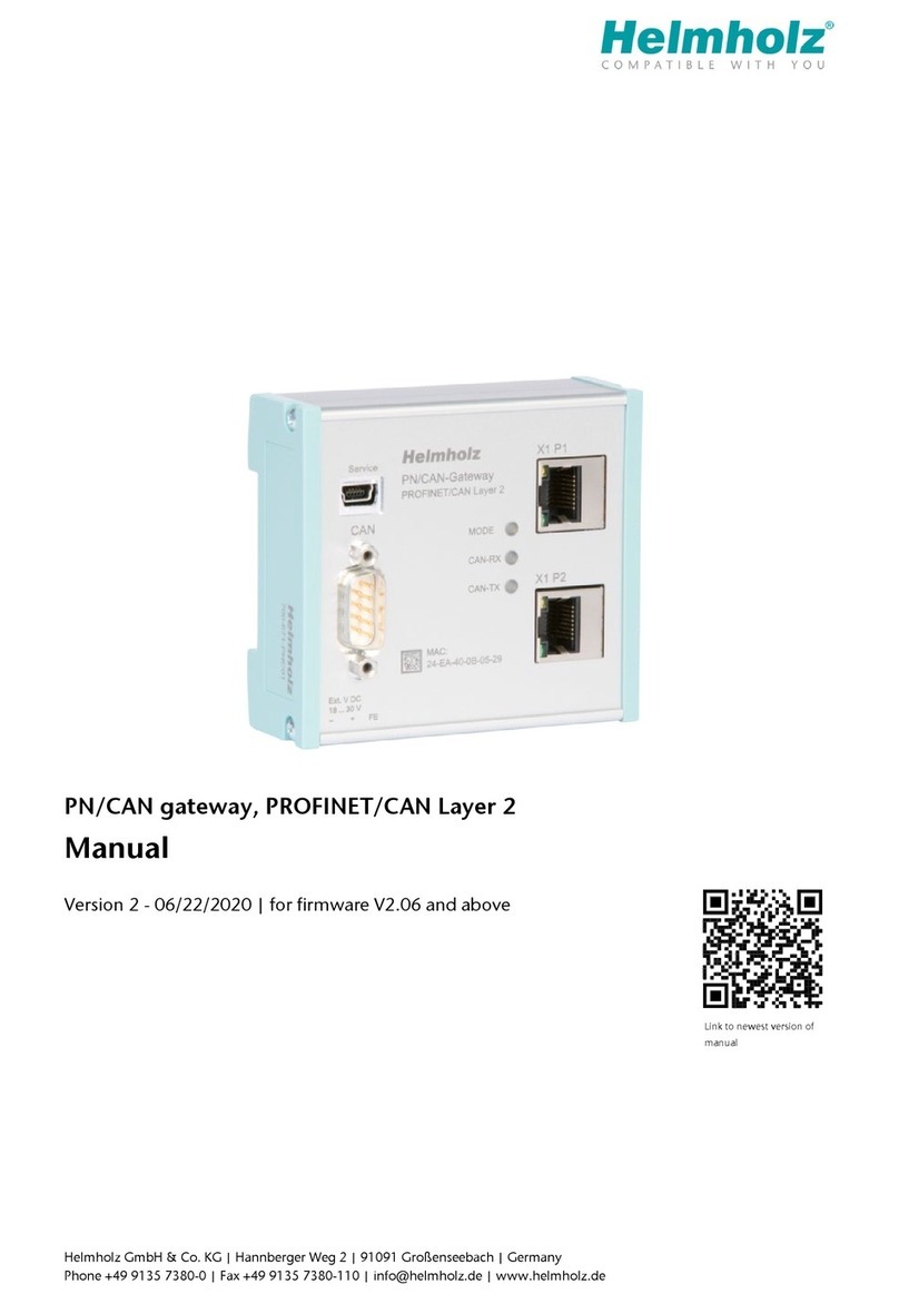
Helmholz PN/CAN Gateway Layer 2 User manual

Helmholz
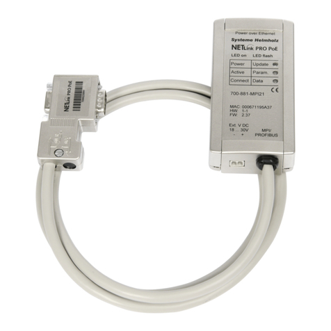
Helmholz NETLink 700-881-MPI21 User manual

Helmholz
Helmholz PN/CAN gateway User manual

Helmholz
Helmholz NETLink User manual

Helmholz
Helmholz PN/CAN gateway User manual

Helmholz
Helmholz WALL IE 700-860-WAL01 User manual

Helmholz
Helmholz PN/CAN gateway User manual

Helmholz
Helmholz 700-671-PNC01 User manual

Helmholz
Helmholz CANopen User manual
Helmholz
Helmholz 700-671-PNC01 User manual