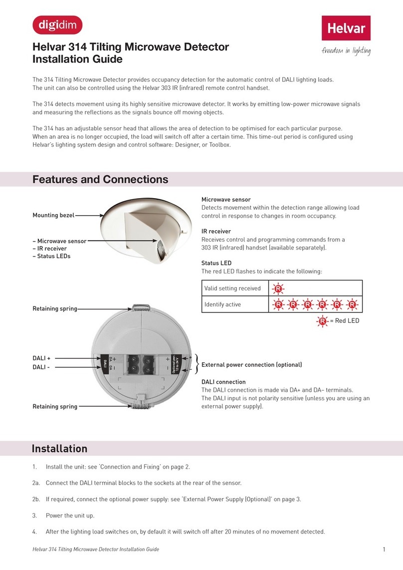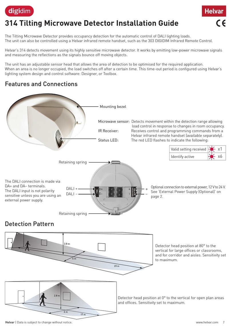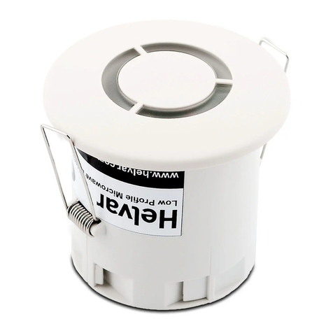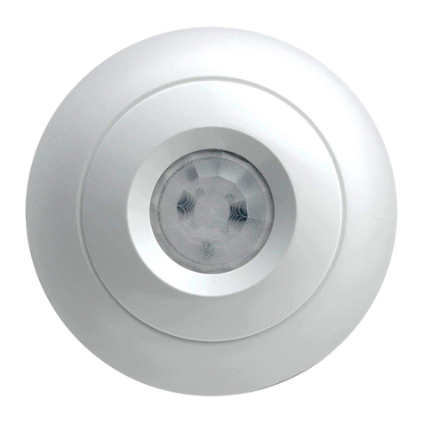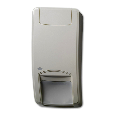
Helvar 313 Low-Profile Microwave Detector: Installation Guide 3
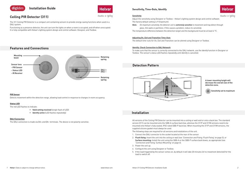
You can use the Helvar 303 IR Remote Control
to send signals to the 313 detector to:
– recall lighting scenes 1–4;
– adjust light levels;
– store current level; and
– install preset levels for scenes 1–4.
Remote Control
Other Functions
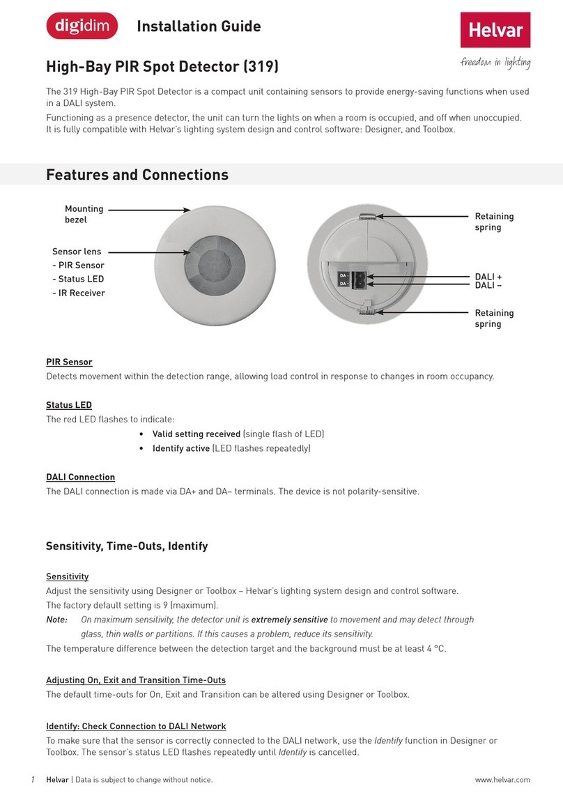
Sensitivity
Adjust the sensitivity using Designer, or Toolbox (Helvar’s lighting system design and control software).
Note: On maximum sensitivity, the detector unit is extremely sensitive to movement and may detect through glass, thin walls or
partitions. If this causes a problem, reduce its sensitivity.
Adjusting On, Exit and Transition Time-Outs
The default time-outs for On, Exit and Transition can be altered using Designer, or Toolbox.
Check Connection to DALI Network
To make sure that the sensor is correctly connected the DALI network, use the Identify function in Designer, or Toolbox.
Using Designer and Toolbox Software
When using Designer, connect the PC to the lighting network via a Helvar router.
When using Toolbox, connect the PC to the lighting network via a Helvar serial or USB interface.
For information about Designer and Toolbox, see the System Software section of www.helvar.com.
Helvar 303 IR Remote Control
See the 303 Remote User Manual
(Helvar Document D004744) for
full details.
External Power Supply (Optional)
The following table gives the various 12 V to 24 V external power supply units that can be used, as well as the sensor hardware
revision needed for each of them. With some models, you must make a wire link between the DALI negative terminal and the
negative terminal of the external power supply, as shown in the figure.
EPS Current
limited
Link from
DA– to EPS–
Sensor hardware
revision
Helvar 401 Yes No Any
Helvar 402 Yes Yes Any
Helvar 403 Yes No Any
Helvar
LL6-U-C LED Slow No 4 or later
Generic
12 V to 24 V No No* 4 or later
* Except in some cases where the generic EPS output is referenced to earth.
+
-
DALI
